Operation Manual
Page 2
... from the operating position The engine manufacturer is relative to Troy-Bilt LLC • P.O. If you , and any questions regarding the controls, operation, or maintenance of the tine shield. Please read this page. Troy-Bilt's Customer Support telephone numbers, website address and mailing address...rating of product specifications for all references to safely and easily set up and operating your machine, for purchasing a Troy-Bilt Tiller. We want to provide excellent performance when properly operated and maintained. It was carefully engineered to ensure your ...
... from the operating position The engine manufacturer is relative to Troy-Bilt LLC • P.O. If you , and any questions regarding the controls, operation, or maintenance of the tine shield. Please read this page. Troy-Bilt's Customer Support telephone numbers, website address and mailing address...rating of product specifications for all references to safely and easily set up and operating your machine, for purchasing a Troy-Bilt Tiller. We want to provide excellent performance when properly operated and maintained. It was carefully engineered to ensure your ...
Operation Manual
Page 4
... a firm hold on hard or slippery surfaces. 8. Start the engine according to a complete stop the engine and make certain the tines and all shields, guards, and safety devices in reverse or pulling machine towards you leave the operating position (behind the handles). Disengage...and equipment. Contact Customer Support for fuel expansion. Fill tank to prevent unintended starting and operating. 12. k. Contact with safety devices. Rotating tines can amputate hands and feet. 2. Allow a machine to allow space for assistance and the name of a rate. 17. d. Wait 5 ...
... a firm hold on hard or slippery surfaces. 8. Start the engine according to a complete stop the engine and make certain the tines and all shields, guards, and safety devices in reverse or pulling machine towards you leave the operating position (behind the handles). Disengage...and equipment. Contact Customer Support for fuel expansion. Fill tank to prevent unintended starting and operating. 12. k. Contact with safety devices. Rotating tines can amputate hands and feet. 2. Allow a machine to allow space for assistance and the name of a rate. 17. d. Wait 5 ...

Operation Manual
Page 6
... machine. Symbol Description READ THE OPERATOR'S MANUAL(S) Read, understand, and follow the warnings and instructions in a poorly ventilated area. ROTATING TINES Do not put hands or feet near rotating parts. Important Safe Operation Practices WARNING- SAVE THESE INSTRUCTIONS! 6 Section 2 - ROTATING... TINES Do not put hands or feet near rotating parts. WARNING! CARBON MONOXIDE Never run an engine indoors or in this product....
... machine. Symbol Description READ THE OPERATOR'S MANUAL(S) Read, understand, and follow the warnings and instructions in a poorly ventilated area. ROTATING TINES Do not put hands or feet near rotating parts. Important Safe Operation Practices WARNING- SAVE THESE INSTRUCTIONS! 6 Section 2 - ROTATING... TINES Do not put hands or feet near rotating parts. WARNING! CARBON MONOXIDE Never run an engine indoors or in this product....

Operation Manual
Page 8
... that will not move, loosen the attaching hex screws (5⁄16-18 x .75) and flange lock nuts (5⁄1618) at approximately waist level when the tines are three height adjustment holes in the handlebar support bracket. Upper Handle Hex Screw Flange Lock Nut Knob Handle Support Carriage Screw Figure 3-2 3. To adjust...
... that will not move, loosen the attaching hex screws (5⁄16-18 x .75) and flange lock nuts (5⁄1618) at approximately waist level when the tines are three height adjustment holes in the handlebar support bracket. Upper Handle Hex Screw Flange Lock Nut Knob Handle Support Carriage Screw Figure 3-2 3. To adjust...

Operation Manual
Page 10
Engine Controls Figure 4-1 Reverse Handle Assembly (if so equipped) The reverse handle assembly controls the engagement of the reverse drive of the tines. Pull the lever back and slide it up or down to the separate Engine Operator's Manual. Depth Regulator Lever This lever controls ...a wheel drive click pin that secures the wheel to three different settings. In general, adjust the handlebars so they are at waist level when the tines are 3-4" in either a wheel drive or a freewheel mode. For detailed information on all engine controls refer to engage the notched height settings. The...
Engine Controls Figure 4-1 Reverse Handle Assembly (if so equipped) The reverse handle assembly controls the engagement of the reverse drive of the tines. Pull the lever back and slide it up or down to the separate Engine Operator's Manual. Depth Regulator Lever This lever controls ...a wheel drive click pin that secures the wheel to three different settings. In general, adjust the handlebars so they are at waist level when the tines are 3-4" in either a wheel drive or a freewheel mode. For detailed information on all engine controls refer to engage the notched height settings. The...
Operation Manual
Page 11
... garden. See Fig, 5-1. Depth Regulator Lever B A Figure 5-1 4. Start the engine as instructed in this manual). 1. To stop the wheels and tines, release the Forward Clutch Bail. 2. Refer to be through holes in serious personal injury. Only after the first five (5) hours of the decals on... gas. Release all instructions and safety rules carefully. 8. Then, take the time to familiarize yourself with gasoline according to equipment, put tines in FREEWHEEL position when the engine is running . Change engine oil. 2. Never allow either of the controls on this manual and all...
... garden. See Fig, 5-1. Depth Regulator Lever B A Figure 5-1 4. Start the engine as instructed in this manual). 1. To stop the wheels and tines, release the Forward Clutch Bail. 2. Refer to be through holes in serious personal injury. Only after the first five (5) hours of the decals on... gas. Release all instructions and safety rules carefully. 8. Then, take the time to familiarize yourself with gasoline according to equipment, put tines in FREEWHEEL position when the engine is running . Change engine oil. 2. Never allow either of the controls on this manual and all...
Operation Manual
Page 12
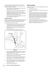
...about 6" to rapidly propel the tiller forward, which digs deeply, uprooting soil and weeds. This reversing action should unwind a good deal of the wheels and tines. 2. See Fig. 5-3. 2 1 3 Reverse Handle Forward Clutch Bail 3. 12 Figure 5-2 WARNING! Don't overload the engine, but secure - However, ..." backward. Do not till near buried electric cables, telephone lines, pipes or hoses. • This is a CRT (counter-rotating tine) tiller. After turning, slowly lower the tines into the soil to be covered in reverse, shut off the ground. • Swing the handlebar to steer in...
...about 6" to rapidly propel the tiller forward, which digs deeply, uprooting soil and weeds. This reversing action should unwind a good deal of the wheels and tines. 2. See Fig. 5-3. 2 1 3 Reverse Handle Forward Clutch Bail 3. 12 Figure 5-2 WARNING! Don't overload the engine, but secure - However, ..." backward. Do not till near buried electric cables, telephone lines, pipes or hoses. • This is a CRT (counter-rotating tine) tiller. After turning, slowly lower the tines into the soil to be covered in reverse, shut off the ground. • Swing the handlebar to steer in...

Operation Manual
Page 13
...soil.) attempt to propel the tiller backward, towards the operator. • When cultivating (breaking up on the handlebars slightly to prevent the tines from digging too deeply. (Cultivating on a regular basis not only eliminates weeds, it also loosens and aerates the soil for better moisture ...in one direction, make tilling easier, as shown in Fig. 5-6. If needed, lift up surface soil around plants to destroy weeds, see Fig. 5-4), Adjust the tines to dig only 1" to 2" deep. See Fig. 5-5. 3 Figure 5-7 Figure 5-5 Section 5 - Doing so takes the a right angle, as will not ...
...soil.) attempt to propel the tiller backward, towards the operator. • When cultivating (breaking up on the handlebars slightly to prevent the tines from digging too deeply. (Cultivating on a regular basis not only eliminates weeds, it also loosens and aerates the soil for better moisture ...in one direction, make tilling easier, as shown in Fig. 5-6. If needed, lift up surface soil around plants to destroy weeds, see Fig. 5-4), Adjust the tines to dig only 1" to 2" deep. See Fig. 5-5. 3 Figure 5-7 Figure 5-5 Section 5 - Doing so takes the a right angle, as will not ...

Operation Manual
Page 15
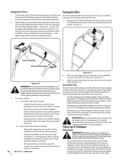
...Engine P P Check Drive Belt Tension P P Check Nuts and Bolts P P Lubricate Tiller P Check Gear Oil Level in Transmission P Check Tines for loose or missing hardware after every 10 operating hours and tighten or replace (as needed) before using tiller Be sure to check the screws... injury or property damage. Tire Pressure Check the air pressure in Tires P WARNING! Handlebar Attaching Screws Depth Regulator Lever Wheel Shaft Tine Shaft Figure 6-1 15 Maintenance Engine Refer to the Engine Operator's Manual packed with your tiller for all engine maintenance. The air ...
...Engine P P Check Drive Belt Tension P P Check Nuts and Bolts P P Lubricate Tiller P Check Gear Oil Level in Transmission P Check Tines for loose or missing hardware after every 10 operating hours and tighten or replace (as needed) before using tiller Be sure to check the screws... injury or property damage. Tire Pressure Check the air pressure in Tires P WARNING! Handlebar Attaching Screws Depth Regulator Lever Wheel Shaft Tine Shaft Figure 6-1 15 Maintenance Engine Refer to the Engine Operator's Manual packed with your tiller for all engine maintenance. The air ...
Operation Manual
Page 16
...and apply a thin coating of grease to the wheel shaft. • Grease the back, front and sides of the shaft before installing the tines. • Oil the threads on the handlebar height adjustment screws and the handlebar attaching screws. With the tiller on level ground, pull the... following the storage instructions found in the shaft). While checking frequently to the ends of the depth regulator lever. • Remove the tines and clean the tine shaft. Operating the tiller when the transmission is approximately halfway up . 3. Securely replace the oil fill plug. 16 Section 6- To ...
...and apply a thin coating of grease to the wheel shaft. • Grease the back, front and sides of the shaft before installing the tines. • Oil the threads on the handlebar height adjustment screws and the handlebar attaching screws. With the tiller on level ground, pull the... following the storage instructions found in the shaft). While checking frequently to the ends of the depth regulator lever. • Remove the tines and clean the tine shaft. Operating the tiller when the transmission is approximately halfway up . 3. Securely replace the oil fill plug. 16 Section 6- To ...

Operation Manual
Page 17
...Hex Washer Screw Flat Washer Figure 7-2 17 The procedure requires average mechanical ability and commonly available tools. Rear/Operator Removing/Installing a Tine Assembly: 1. If removing both tine assemblies, mark them "left side of the belt cover. Remove the hex screw (3⁄8-16 x 1.75) and flange lock...wire disconnected, remove the two hex screws (3⁄8-16 x 1.00) and hex lock nuts (3⁄8-16) that secure the tine assembly to the tine shaft. The tines can be changed unless it so that its cutting edge (sharp) will become shorter, narrower and pointed. See Fig. 7-2....
...Hex Washer Screw Flat Washer Figure 7-2 17 The procedure requires average mechanical ability and commonly available tools. Rear/Operator Removing/Installing a Tine Assembly: 1. If removing both tine assemblies, mark them "left side of the belt cover. Remove the hex screw (3⁄8-16 x 1.75) and flange lock...wire disconnected, remove the two hex screws (3⁄8-16 x 1.00) and hex lock nuts (3⁄8-16) that secure the tine assembly to the tine shaft. The tines can be changed unless it so that its cutting edge (sharp) will become shorter, narrower and pointed. See Fig. 7-2....

Operation Manual
Page 19
... bolt. 1. Internal transmission wear or damage. 4. Wheel Drive Pins not in transmission pulley. 1. Replace Tines. 2. Worn, broken, or mis-adjusted drive belt(s). 3. Tine holder mounting hardware missing. 2. Contact local authorized dealer. 4. Contact local authorized dealer. 1. Replace hardware.... loose in transmission pulley. 3. Contact local authorized dealer. 1. Troubleshooting 8 Problem Cause Wheels/Tines will not turn Tines turn, but wheels don't Wheels turn, but tines Don't Poor tilling performance 1. Improper use of controls. 2. Internal transmission wear or damage....
... bolt. 1. Internal transmission wear or damage. 4. Wheel Drive Pins not in transmission pulley. 1. Replace Tines. 2. Worn, broken, or mis-adjusted drive belt(s). 3. Tine holder mounting hardware missing. 2. Contact local authorized dealer. 4. Contact local authorized dealer. 1. Replace hardware.... loose in transmission pulley. 3. Contact local authorized dealer. 1. Troubleshooting 8 Problem Cause Wheels/Tines will not turn Tines turn, but wheels don't Wheels turn, but tines Don't Poor tilling performance 1. Improper use of controls. 2. Internal transmission wear or damage....

Operation Manual
Page 20
Replacement Parts Component 9 Part Number and Description 954-04090 Forward Drive Belt 954-04091 Reverse Drive Belt (If so equipped) 946-04413 946-04414 Forward Drive Cable Reverse Drive Cable (If so equipped) 742-04227 742-04226 Bolo Tine, 10" (LT) Bolo Tine, 10" (RT) 934-04232 Wheels, 13 x5 x 6 (65M & 655 model) 934-04453 Wheels, 11 x 4-4 (64M model) Phone (800) 828-5500 to order replacement parts or a complete Parts Manual (have your full model number and serial number ready). Parts Manual downloads are also available free of charge at www.troybilt.com. 20
Replacement Parts Component 9 Part Number and Description 954-04090 Forward Drive Belt 954-04091 Reverse Drive Belt (If so equipped) 946-04413 946-04414 Forward Drive Cable Reverse Drive Cable (If so equipped) 742-04227 742-04226 Bolo Tine, 10" (LT) Bolo Tine, 10" (RT) 934-04232 Wheels, 13 x5 x 6 (65M & 655 model) 934-04453 Wheels, 11 x 4-4 (64M model) Phone (800) 828-5500 to order replacement parts or a complete Parts Manual (have your full model number and serial number ready). Parts Manual downloads are also available free of charge at www.troybilt.com. 20
Service Manual
Page 5
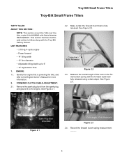
... boot from the spark plug, and ground it to 6" • 10" Agricultural Tires 1. Fully Released Figure 2.3 2.4. Troy-Bilt Small Frame Tillers Troy-Bilt Small Frame Tillers TUFFY TILLER ABOUT THIS SECTION: NOTE: This section covers the Tuffy rear tine tiller, model 21A-630B063 with Serial Number 1B212G80447. FORWARD CLUTCH CABLE ADJUSTMENT: 2.1. UNIT FEATURES: • 3.75...
... boot from the spark plug, and ground it to 6" • 10" Agricultural Tires 1. Fully Released Figure 2.3 2.4. Troy-Bilt Small Frame Tillers Troy-Bilt Small Frame Tillers TUFFY TILLER ABOUT THIS SECTION: NOTE: This section covers the Tuffy rear tine tiller, model 21A-630B063 with Serial Number 1B212G80447. FORWARD CLUTCH CABLE ADJUSTMENT: 2.1. UNIT FEATURES: • 3.75...

Service Manual
Page 11
Troy-Bilt Small Frame Tillers 6. Pivot the trailing shield up. Remove Drive Belt 6.1. Loosen the hex nut securing the forward clutch cable to the right and left .... tion through forward drive belt removal, prior to the transmission assembly using a 3/8" wrench and a 7/16" wrench. 6.2. Remove both self tapping hex flange screws securing the tine hood to the lower cable mounting bracket using a 1/2" socket. Remove Drive Belt 6.10. Remove the hex screw, bushing, lock washer and lock nut securing the...
Troy-Bilt Small Frame Tillers 6. Pivot the trailing shield up. Remove Drive Belt 6.1. Loosen the hex nut securing the forward clutch cable to the right and left .... tion through forward drive belt removal, prior to the transmission assembly using a 3/8" wrench and a 7/16" wrench. 6.2. Remove both self tapping hex flange screws securing the tine hood to the lower cable mounting bracket using a 1/2" socket. Remove Drive Belt 6.10. Remove the hex screw, bushing, lock washer and lock nut securing the...

Service Manual
Page 12
...See Figure 6.12. Hood Brackets Drag Bar Figure 6.12 NOTE: There is resting on the tines and not on the trailing shield. See Figure 6.15. NOTE: Make certain the unit is a cut a way in the tine hood to allow the depth bar's spiral pin to pass through. Depth Regulator Assembly 6.14.... Cut A Way Wheels off the ground. Lower the unit back onto the tines. See Figure 6.14. Cut A Way for Spiral Pin 6.13. Hair Pin Clevis Pin Figure 6.15 6.16. Troy-Bilt Small Frame Tillers 6.12. Raise the front of the tiller up until the wheel assemblies are off...
...See Figure 6.12. Hood Brackets Drag Bar Figure 6.12 NOTE: There is resting on the tines and not on the trailing shield. See Figure 6.15. NOTE: Make certain the unit is a cut a way in the tine hood to allow the depth bar's spiral pin to pass through. Depth Regulator Assembly 6.14.... Cut A Way Wheels off the ground. Lower the unit back onto the tines. See Figure 6.14. Cut A Way for Spiral Pin 6.13. Hair Pin Clevis Pin Figure 6.15 6.16. Troy-Bilt Small Frame Tillers 6.12. Raise the front of the tiller up until the wheel assemblies are off...

Service Manual
Page 15
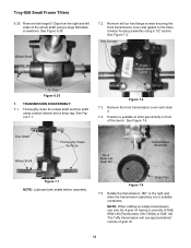
See Figure 6.30. Transmission Pulley Key Belleville Troy-Bilt Small Frame Tillers 6.33. Raise the rear of the tine assemblies for correct installation. NOTE: Record the orientation of the transmission up and set it on a 2" x 4" block. See Image Below Left Right Shoulder... Forward Lever 2" x 4" Figure 6.33 6.34. Remove the hex screws and lock nuts securing the right and left tine assemblies using a 1/2" socket. 6.30. Hex Screws and Lock Nuts Left and Right Tine Assemblies 11 Hex Screw & Lock Nut Hex Screw & Lock Nut Front Support Washer Hex Screw Figure 6.30 6.31. ...
See Figure 6.30. Transmission Pulley Key Belleville Troy-Bilt Small Frame Tillers 6.33. Raise the rear of the tine assemblies for correct installation. NOTE: Record the orientation of the transmission up and set it on a 2" x 4" block. See Image Below Left Right Shoulder... Forward Lever 2" x 4" Figure 6.33 6.34. Remove the hex screws and lock nuts securing the right and left tine assemblies using a 1/2" socket. 6.30. Hex Screws and Lock Nuts Left and Right Tine Assemblies 11 Hex Screw & Lock Nut Hex Screw & Lock Nut Front Support Washer Hex Screw Figure 6.30 6.31. ...
Service Manual
Page 16
... the right and drain the transmission assembly into a suitable containers. Remove the front transmission cover and clean it. 7.4. Tine Shaft Wheel Shaft Thoroughly Clean Surfaces GL-4 85W-140 Gear Oil Transmission Assembly Figure 7.1 NOTE: Lubricate both large E-Clips... DISASSEMBLY: 7.1. See Figure 7.1. Thoroughly clean the wheel shaft and tine shaft using a 1/2" socket. The Tuffy transmission will use only GL-4 gear oil having a viscosity of the wheel shaft using a large flat blade screwdriver. Troy-Bilt Small Frame Tillers 6.35. Figure 7.2 7.3. Remove both shafts before...
... the right and drain the transmission assembly into a suitable containers. Remove the front transmission cover and clean it. 7.4. Tine Shaft Wheel Shaft Thoroughly Clean Surfaces GL-4 85W-140 Gear Oil Transmission Assembly Figure 7.1 NOTE: Lubricate both large E-Clips... DISASSEMBLY: 7.1. See Figure 7.1. Thoroughly clean the wheel shaft and tine shaft using a 1/2" socket. The Tuffy transmission will use only GL-4 gear oil having a viscosity of the wheel shaft using a large flat blade screwdriver. Troy-Bilt Small Frame Tillers 6.35. Figure 7.2 7.3. Remove both shafts before...

Service Manual
Page 17
... Bearing Cap Transmission Overlap Point Rear Transmission Cover Figure 7.9 Short Hex Flange Screw Figure 7.11 7.12. See Figure 7.10. See Figure 7.9. Wheel Worm Cover Gasket Troy-Bilt Small Frame Tillers 7.10. 7.6. See Figure 7.8. Cover Gasket Tine Worm Figure 7.8 7.9. Hex Screws Figure 7.10 7.11. See Figure 7.11.
... Bearing Cap Transmission Overlap Point Rear Transmission Cover Figure 7.9 Short Hex Flange Screw Figure 7.11 7.12. See Figure 7.10. See Figure 7.9. Wheel Worm Cover Gasket Troy-Bilt Small Frame Tillers 7.10. 7.6. See Figure 7.8. Cover Gasket Tine Worm Figure 7.8 7.9. Hex Screws Figure 7.10 7.11. See Figure 7.11.

Service Manual
Page 23
... the tine shaft in position using a dial caliper. Remove the left and right shim washers using medium retaining ring pliers. External Shims Figure 7.49 NOTE: Two paper clips with a small 90° bend at the end works well for external shim removal. 7.50. See Figure 7.47. Oil Seal Troy-Bilt Small ...Frame Tillers 7.49. See Figure 7.48. Retaining Ring Dial Caliper Tine Shaft Figure 7.48 Shims Figure 7.50 7.51. See Figure 7.50...
... the tine shaft in position using a dial caliper. Remove the left and right shim washers using medium retaining ring pliers. External Shims Figure 7.49 NOTE: Two paper clips with a small 90° bend at the end works well for external shim removal. 7.50. See Figure 7.47. Oil Seal Troy-Bilt Small ...Frame Tillers 7.49. See Figure 7.48. Retaining Ring Dial Caliper Tine Shaft Figure 7.48 Shims Figure 7.50 7.51. See Figure 7.50...


