User Manual
Page 3
User's Manual F.01U.127.338 | 2.0 | 2009.05 General Purpose LCD Monitors Table of Contents 1 1.1 1.2 1.3 1.4 2 2.1 3 4 4.1 5 5.1 5.2 6 6.1 6.2 6.2.1 6.2.2 6.3 6.4 6.5 6.6 7 7.1 7.2 7.3 7.4 7.5 7.6 Safety Important Safety Instructions Safety Precautions Important Notices Customer Support and Service Unpacking ... Contents | en iii 1 1 3 3 8 9 9 10 12 12 13 13 13 13 13 14 14 14 15 16 16 16 17 17 18 19 19 20 21 Bosch Security Systems, Inc.
User's Manual F.01U.127.338 | 2.0 | 2009.05 General Purpose LCD Monitors Table of Contents 1 1.1 1.2 1.3 1.4 2 2.1 3 4 4.1 5 5.1 5.2 6 6.1 6.2 6.2.1 6.2.2 6.3 6.4 6.5 6.6 7 7.1 7.2 7.3 7.4 7.5 7.6 Safety Important Safety Instructions Safety Precautions Important Notices Customer Support and Service Unpacking ... Contents | en iii 1 1 3 3 8 9 9 10 12 12 13 13 13 13 13 14 14 14 15 16 16 16 17 17 18 19 19 20 21 Bosch Security Systems, Inc.

User Manual
Page 4
iv en | Table of Contents 8 Power Management 8.1 Power Consumption 8.2 LED Indicator 9 Trouble Shooting Guide 10 Maintenance 11 Technical Specifications General Purpose LCD Monitors 22 22 22 23 24 25 F.01U.127.338 | 2.0 | 2009.05 User's Manual Bosch Security Systems, Inc.
iv en | Table of Contents 8 Power Management 8.1 Power Consumption 8.2 LED Indicator 9 Trouble Shooting Guide 10 Maintenance 11 Technical Specifications General Purpose LCD Monitors 22 22 22 23 24 25 F.01U.127.338 | 2.0 | 2009.05 User's Manual Bosch Security Systems, Inc.

User Manual
Page 5
... any area classified as radiators, heaters, stoves, or other controls may also be used. This can cause fire or electrical shock. 9. Power disconnect - Bosch Security Systems, Inc. User's Manual F.01U.127.338 | 2.0 | 2009.05 Generally, using a dry cloth for long periods, unplug the unit from the outlet before operating the unit. 1. To...
... any area classified as radiators, heaters, stoves, or other controls may also be used. This can cause fire or electrical shock. 9. Power disconnect - Bosch Security Systems, Inc. User's Manual F.01U.127.338 | 2.0 | 2009.05 Generally, using a dry cloth for long periods, unplug the unit from the outlet before operating the unit. 1. To...

User Manual
Page 6
... unit exhibits a distinct change or modification of power source indicated on the equipment; - F.01U.127.338 | 2.0 | 2009.05 User's Manual Bosch Security Systems, Inc. 2 en | Safety General Purpose LCD Monitors 11. Installation - Install in accordance with EN60950. User-supplied wiring must comply... or plug is damaged; - an object has fallen into the unit. - For external power supplied units, use attachments/accessories specified by Bosch, could void the warranty or, in performance; - Opening or removing covers may expose you to moisture, water, and/or inclement weather...
... unit exhibits a distinct change or modification of power source indicated on the equipment; - F.01U.127.338 | 2.0 | 2009.05 User's Manual Bosch Security Systems, Inc. 2 en | Safety General Purpose LCD Monitors 11. Installation - Install in accordance with EN60950. User-supplied wiring must comply... or plug is damaged; - an object has fallen into the unit. - For external power supplied units, use attachments/accessories specified by Bosch, could void the warranty or, in performance; - Opening or removing covers may expose you to moisture, water, and/or inclement weather...

User Manual
Page 7
... policy that relates directly or indirectly to the unit. Important Notices Accessories - Incorporate an all -pole switch as "Dangerous Voltage" inside the product. Camera signal - Bosch Security Systems, Inc. Medium risk: Indicates a potentially hazardous situation. If not avoided, this unit on an unstable stand, tripod, bracket, or mount. Use only... cause the cart/unit combination to important instructions accompanying the unit. i 1.3 Safety Precautions DANGER! Alerts the user to overturn. All-pole power switch - User's Manual F.01U.127.338 | 2.0 | 2009.05
... policy that relates directly or indirectly to the unit. Important Notices Accessories - Incorporate an all -pole switch as "Dangerous Voltage" inside the product. Camera signal - Bosch Security Systems, Inc. Medium risk: Indicates a potentially hazardous situation. If not avoided, this unit on an unstable stand, tripod, bracket, or mount. Use only... cause the cart/unit combination to important instructions accompanying the unit. i 1.3 Safety Precautions DANGER! Alerts the user to overturn. All-pole power switch - User's Manual F.01U.127.338 | 2.0 | 2009.05

User Manual
Page 8
... grounding terminal. - The installation for use in accordance with NEC800 (CEC Section 60). F.01U.127.338 | 2.0 | 2009.05 User's Manual Bosch Security Systems, Inc. 4 en | Safety General Purpose LCD Monitors Coax grounding: - Connect outdoor equipment to the unit's inputs only after this...disused electronic and electrical products. This symbol means that can be equipped with a polarized alternating current line plug (a plug with care. Bosch has a strong commitment towards the environment. Use proper CMOS/MOS-FET handling precautions to the unit. - NOTE: Wear required grounded...
... grounding terminal. - The installation for use in accordance with NEC800 (CEC Section 60). F.01U.127.338 | 2.0 | 2009.05 User's Manual Bosch Security Systems, Inc. 4 en | Safety General Purpose LCD Monitors Coax grounding: - Connect outdoor equipment to the unit's inputs only after this...disused electronic and electrical products. This symbol means that can be equipped with a polarized alternating current line plug (a plug with care. Bosch has a strong commitment towards the environment. Use proper CMOS/MOS-FET handling precautions to the unit. - NOTE: Wear required grounded...
User Manual
Page 9
...Federal Communications Commission, helpful: How to operate the equipment. The user may cause harmful interference to back up all units. User's Manual F.01U.127.338 | 2.0 | 2009.05 Because the ISDN circuits are treated like telephone-network voltage, avoid connecting the SELV... operation. SELV circuits should consult the dealer or an experienced radio/television technician for all analog and digital information. therefore, Bosch Security Systems cannot be made. FCC & ICES INFORMATION (U.S.A. NOTICE! this device may be required to digital video recording; If...
...Federal Communications Commission, helpful: How to operate the equipment. The user may cause harmful interference to back up all units. User's Manual F.01U.127.338 | 2.0 | 2009.05 Because the ISDN circuits are treated like telephone-network voltage, avoid connecting the SELV... operation. SELV circuits should consult the dealer or an experienced radio/television technician for all analog and digital information. therefore, Bosch Security Systems cannot be made. FCC & ICES INFORMATION (U.S.A. NOTICE! this device may be required to digital video recording; If...

User Manual
Page 11
...no liability for damage resulting directly or indirectly from faults, incompleteness or discrepancies between the user guide and the product described. User's Manual F.01U.127.338 | 2.0 | 2009.05 Bosch Security Systems, Inc. and is the intellectual property of the user guide can change without notice. General Purpose LCD Monitors Safety |... likely to be registered trademarks and must be treated accordingly. The ongoing i development of the products may mean that the content of Bosch Security Systems, Inc. NOTICE! The text was complete and correct at the time of printing.
...no liability for damage resulting directly or indirectly from faults, incompleteness or discrepancies between the user guide and the product described. User's Manual F.01U.127.338 | 2.0 | 2009.05 Bosch Security Systems, Inc. and is the intellectual property of the user guide can change without notice. General Purpose LCD Monitors Safety |... likely to be registered trademarks and must be treated accordingly. The ongoing i development of the products may mean that the content of Bosch Security Systems, Inc. NOTICE! The text was complete and correct at the time of printing.
User Manual
Page 12
... 800-366-2283 or 585-340-4162 Fax: 800-366-1329 Email: cctv.repair@us.bosch.com Customer Service Telephone: 888-289-0096 Fax: 585-223-9180 Email: security.sales@us.bosch.com Technical Support Telephone: 800-326-1450 Fax: 585-223-3508 or 717-735-6560... (0) 1495 274280 Email: [email protected] More information For additional information, please contact your Bosch Security Systems representative or visit our web site at www.boschsecurity.com F.01U.127.338 | 2.0 | 2009.05 User's Manual Bosch Security Systems, Inc. 8 en | Safety 1.4 General Purpose LCD Monitors Customer Support and ...
... 800-366-2283 or 585-340-4162 Fax: 800-366-1329 Email: cctv.repair@us.bosch.com Customer Service Telephone: 888-289-0096 Fax: 585-223-9180 Email: security.sales@us.bosch.com Technical Support Telephone: 800-326-1450 Fax: 585-223-3508 or 717-735-6560... (0) 1495 274280 Email: [email protected] More information For additional information, please contact your Bosch Security Systems representative or visit our web site at www.boschsecurity.com F.01U.127.338 | 2.0 | 2009.05 User's Manual Bosch Security Systems, Inc. 8 en | Safety 1.4 General Purpose LCD Monitors Customer Support and ...
User Manual
Page 13
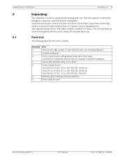
... VAC, 50/60 Hz Remote control with two (2) AAA batteries Audio cable PC-style Bosch Security Systems, Inc. Parts List The following table lists the parts included: Quantity 1 1 2 1 1 1 1 Part UML-151-90, UML-171-90, or UML-191-90 Color LCD Flat Panel Monitor Installation manual Power Cords, 3-wire with grounded plug 1.8 m (6 ft) long: one with a U.S plug type and...
... VAC, 50/60 Hz Remote control with two (2) AAA batteries Audio cable PC-style Bosch Security Systems, Inc. Parts List The following table lists the parts included: Quantity 1 1 2 1 1 1 1 Part UML-151-90, UML-171-90, or UML-191-90 Color LCD Flat Panel Monitor Installation manual Power Cords, 3-wire with grounded plug 1.8 m (6 ft) long: one with a U.S plug type and...

User Manual
Page 14
... Remote control sensor. 8 Power Button / LED Power On (green) Indicator Standby (blinking red) Unsupported Mode (green) Power Off (red) F.01U.127.338 | 2.0 | 2009.05 User's Manual Bosch Security Systems, Inc.
... Remote control sensor. 8 Power Button / LED Power On (green) Indicator Standby (blinking red) Unsupported Mode (green) Power Off (red) F.01U.127.338 | 2.0 | 2009.05 User's Manual Bosch Security Systems, Inc.

User Manual
Page 15
... (L+R) PC Stereo IN Description UML-151-50: 3.3 A UML-171-50: 4.1 A UML-191-90: 4.1 A PC Signal Input Composite signal input for AV1 Video looping output for AV1 Composite signal input for AV2 Video looping output for AV2 Y/C separated signal input Y/C separated signal looping output Stereo audio signal input Bosch Security Systems, Inc. User's Manual F.01U.127.338 | 2.0 | 2009...
... (L+R) PC Stereo IN Description UML-151-50: 3.3 A UML-171-50: 4.1 A UML-191-90: 4.1 A PC Signal Input Composite signal input for AV1 Video looping output for AV1 Composite signal input for AV2 Video looping output for AV2 Y/C separated signal input Y/C separated signal looping output Stereo audio signal input Bosch Security Systems, Inc. User's Manual F.01U.127.338 | 2.0 | 2009...

User Manual
Page 16
..., decreases item values in an OSD menu. Figure 4.1 Remote Control Battery Placement 3. Note: Replace batteries when required or at least once a year. Dispose of the Bosch remote control. EXIT Exits the OSD. UP Moves the cursor up in an OSD menu, or decreases volume. ENTER Accepts your selection or displays the... remote over (buttons facing down) and push down in the OSD menus. Slide the battery cover back into place. F.01U.127.338 | 2.0 | 2009.05 User's Manual Bosch Security Systems, Inc.
..., decreases item values in an OSD menu. Figure 4.1 Remote Control Battery Placement 3. Note: Replace batteries when required or at least once a year. Dispose of the Bosch remote control. EXIT Exits the OSD. UP Moves the cursor up in an OSD menu, or decreases volume. ENTER Accepts your selection or displays the... remote over (buttons facing down) and push down in the OSD menus. Slide the battery cover back into place. F.01U.127.338 | 2.0 | 2009.05 User's Manual Bosch Security Systems, Inc.
User Manual
Page 17
...NTSC/PAL Installing the Monitor This chapter outlines the procedures to all local codes. Bosch Security Systems, Inc. High-resolution Display - 1024 x 768 (UML-151-90) - 1280 x 1024 (UML-171-90) - 1280 x 1024 (UML-191-90) - Ventilation To prevent overheating, ensure that the ventilation openings on the rear .... - 15-inch, 17-inch, and 19-inch models - 100-240 VAC Power Supply - In addition, each model. User's Manual F.01U.127.338 | 2.0 | 2009.05 Y/C Input (S-Video) - Monitor control functions are not covered. General Purpose LCD Monitors Description | en...
...NTSC/PAL Installing the Monitor This chapter outlines the procedures to all local codes. Bosch Security Systems, Inc. High-resolution Display - 1024 x 768 (UML-151-90) - 1280 x 1024 (UML-171-90) - 1280 x 1024 (UML-191-90) - Ventilation To prevent overheating, ensure that the ventilation openings on the rear .... - 15-inch, 17-inch, and 19-inch models - 100-240 VAC Power Supply - In addition, each model. User's Manual F.01U.127.338 | 2.0 | 2009.05 Y/C Input (S-Video) - Monitor control functions are not covered. General Purpose LCD Monitors Description | en...
User Manual
Page 18
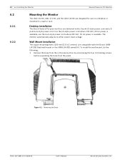
... automatically adjusts to a wall or rack. Figure 6.1 Removing the Base F.01U.127.338 | 2.0 | 2009.05 User's Manual Bosch Security Systems, Inc. use on a desktop or mounted to either power input voltage. Remove the base from the LCD panel ...Bosch UMMLW-20B fixed wall mount or the UMM-LW-30B swivel/tilt. Wall Mount Installation The square mounting holes (100 mm [3.9 in.] centers) are compatible with a 3-pole US-style power cord and a 3pole Euro-style power cord. 14 en | Installing the Monitor General Purpose LCD Monitors 6.2 6.2.1 6.2.2 Mounting the Monitor The UML-151-90, UML...
... automatically adjusts to a wall or rack. Figure 6.1 Removing the Base F.01U.127.338 | 2.0 | 2009.05 User's Manual Bosch Security Systems, Inc. use on a desktop or mounted to either power input voltage. Remove the base from the LCD panel ...Bosch UMMLW-20B fixed wall mount or the UMM-LW-30B swivel/tilt. Wall Mount Installation The square mounting holes (100 mm [3.9 in.] centers) are compatible with a 3-pole US-style power cord and a 3pole Euro-style power cord. 14 en | Installing the Monitor General Purpose LCD Monitors 6.2 6.2.1 6.2.2 Mounting the Monitor The UML-151-90, UML...

User Manual
Page 19
...-through function. NOTE: All video inputs are provided with the Bosch mounting kit. 6.3 i Figure 6.2 Mounting the Device Connecting the Composite Video Signal to 75 ohm by the input of the signal on the rear of the monitor Bosch Security Systems, Inc. The impedance is also connected to the ...output connector, the video signal can be connected in .) centers. User's Manual F.01U.127.338 | 2.0 | 2009.05 The square mounting hole patterns are two...
...-through function. NOTE: All video inputs are provided with the Bosch mounting kit. 6.3 i Figure 6.2 Mounting the Device Connecting the Composite Video Signal to 75 ohm by the input of the signal on the rear of the monitor Bosch Security Systems, Inc. The impedance is also connected to the ...output connector, the video signal can be connected in .) centers. User's Manual F.01U.127.338 | 2.0 | 2009.05 The square mounting hole patterns are two...

User Manual
Page 20
... Single / Multiple Monitor Configuration Figure 6.5 Single Monitor Configuration Reference # 1 2 3 4 Description Video Camera VIDEO 1 (AV1) IN VIDEO 1 (AV1) OUT VCR F.01U.127.338 | 2.0 | 2009.05 User's Manual Bosch Security Systems, Inc.
... Single / Multiple Monitor Configuration Figure 6.5 Single Monitor Configuration Reference # 1 2 3 4 Description Video Camera VIDEO 1 (AV1) IN VIDEO 1 (AV1) OUT VCR F.01U.127.338 | 2.0 | 2009.05 User's Manual Bosch Security Systems, Inc.

User Manual
Page 21
... Power On (green) Indicator Standby (blinking red) Unsupported Mode (green) Power Off (red) Bosch Security Systems, Inc. Figure 7.1 Front Panel Buttons Reference # Button Description 1 Input Button Selects the signal to the UML-151-90, UML-171-90, or the UML-191-90. the OSD. User's Manual F.01U.127.338 | 2.0 | 2009.05 Decreases volume. 6 Increases the value when in...
... Power On (green) Indicator Standby (blinking red) Unsupported Mode (green) Power Off (red) Bosch Security Systems, Inc. Figure 7.1 Front Panel Buttons Reference # Button Description 1 Input Button Selects the signal to the UML-151-90, UML-171-90, or the UML-191-90. the OSD. User's Manual F.01U.127.338 | 2.0 | 2009.05 Decreases volume. 6 Increases the value when in...
User Manual
Page 22
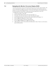
... button to toggle the OSD values. 8. Press the Power button to select a menu. 6. F.01U.127.338 | 2.0 | 2009.05 User's Manual Bosch Security Systems, Inc. The LCD is no Exit button, press the Menu button. Press the and the button to enter the selected ...select operating parameters. 18 en | Navigating the Monitor General Purpose LCD Monitors 7.2 Navigating the Monitor On-screen Display (OSD) The UML-151-90, UML-171-90, and the UML-191-90 have two (2) modes: Video and VGA. Note: If there is programmed through the on the unit (see Figure 7.1). 5. Connect...
... button to toggle the OSD values. 8. Press the Power button to select a menu. 6. F.01U.127.338 | 2.0 | 2009.05 User's Manual Bosch Security Systems, Inc. The LCD is no Exit button, press the Menu button. Press the and the button to enter the selected ...select operating parameters. 18 en | Navigating the Monitor General Purpose LCD Monitors 7.2 Navigating the Monitor On-screen Display (OSD) The UML-151-90, UML-171-90, and the UML-191-90 have two (2) modes: Video and VGA. Note: If there is programmed through the on the unit (see Figure 7.1). 5. Connect...

User Manual
Page 23
... the Menu button to save any changes, then press the Menu button again to adjust the Language, OSD Tone, Blue Screen and Key Lock. User's Manual F.01U.127.338 | 2.0 | 2009.05 Set Up Enables user to Reset the factory default settings and to exit the OSD. Press the Menu button to... 50 50 G 100 20 :Move :Input :Menu Table 7.1 Custom Menu (Video Mode) Custom Brightness 60 Contrast 55 :Move :Input :Menu Table 7.2 Custom Menu (PC Mode) Bosch Security Systems, Inc.
... the Menu button to save any changes, then press the Menu button again to adjust the Language, OSD Tone, Blue Screen and Key Lock. User's Manual F.01U.127.338 | 2.0 | 2009.05 Set Up Enables user to Reset the factory default settings and to exit the OSD. Press the Menu button to... 50 50 G 100 20 :Move :Input :Menu Table 7.1 Custom Menu (Video Mode) Custom Brightness 60 Contrast 55 :Move :Input :Menu Table 7.2 Custom Menu (PC Mode) Bosch Security Systems, Inc.