Owner's Manual (English)
Page 6
...Volume 55 Preset Sound Settings (Sound Mode) 56 Sound Setting Adjustment - Add / Delete Channel (Manual Tuning 37 - CONTENTS WARNING / CAUTION 1 SAFETY INSTRUCTIONS 2 FEATURE OF THIS TV 6 PREPARATION Accessories 7 Front Panel Information 8 Back Panel Information 10 Stand Installation 12 VESA Wall Mounting 13 ... Setup 21 VCR Setup 23 Other A/V Source Setup 25 PC Setup 26 Audio Out Setup 31 WATCHING TV / CHANNEL CONTROL Remote Control Functions 32 Turning On TV 34 Channel Selection 34 Volume Adjustment 34 On-Screen Menus Selection 35 Channel Setup - Preset 45 Color...
...Volume 55 Preset Sound Settings (Sound Mode) 56 Sound Setting Adjustment - Add / Delete Channel (Manual Tuning 37 - CONTENTS WARNING / CAUTION 1 SAFETY INSTRUCTIONS 2 FEATURE OF THIS TV 6 PREPARATION Accessories 7 Front Panel Information 8 Back Panel Information 10 Stand Installation 12 VESA Wall Mounting 13 ... Setup 21 VCR Setup 23 Other A/V Source Setup 25 PC Setup 26 Audio Out Setup 31 WATCHING TV / CHANNEL CONTROL Remote Control Functions 32 Turning On TV 34 Channel Selection 34 Volume Adjustment 34 On-Screen Menus Selection 35 Channel Setup - Preset 45 Color...

Owner's Manual (English)
Page 7
Auto Clock Setup 67 Manual Clock Setup 68 Auto On/Off Timer Setting 69 Sleep Timer Setting 70 Auto Shut-off Setting 71 PARENTAL CONTROL / RATINGS Set Password & Lock System 72 Channel Blocking 74 External Input Blocking 74 Movie & TV Rating 75 APPENDIX Troubleshooting 78 Maintenance 80 Product Specifications 81 Programming the Remote Control 83 IR Codes 87 External Control Through RS-232C 89 Open Source License 96 5 TIME SETTING Clock Setting -
Auto Clock Setup 67 Manual Clock Setup 68 Auto On/Off Timer Setting 69 Sleep Timer Setting 70 Auto Shut-off Setting 71 PARENTAL CONTROL / RATINGS Set Password & Lock System 72 Channel Blocking 74 External Input Blocking 74 Movie & TV Rating 75 APPENDIX Troubleshooting 78 Maintenance 80 Product Specifications 81 Programming the Remote Control 83 IR Codes 87 External Control Through RS-232C 89 Open Source License 96 5 TIME SETTING Clock Setting -

Owner's Manual (English)
Page 8
... of time. It has 2 HDMI ports that connect audio and video devices with TV. I Avoid touching the LCD screen or holding your local authority. 6 b. On Disposal a. The fluorescent lamp used in accordance to the HDMI (high-definition multimedia interface), LG TV with this product must be carried out in this product with one cable.... High-resolution digital television broadcast and playback system composed of this product contains a small amount of your finger(s) against it is nothing wrong with one remote control.
... of time. It has 2 HDMI ports that connect audio and video devices with TV. I Avoid touching the LCD screen or holding your local authority. 6 b. On Disposal a. The fluorescent lamp used in accordance to the HDMI (high-definition multimedia interface), LG TV with this product must be carried out in this product with one cable.... High-resolution digital television broadcast and playback system composed of this product contains a small amount of your finger(s) against it is nothing wrong with one remote control.

Owner's Manual (English)
Page 9
... p.16) the twist holder. (Refer to p.16) D-sub 15 pin Cable For LCD TV models This feature is not available for all models Option Extras 2-Eye-bolts (Refer to...p.12) 7 ENU ENTER RATIO SIMPLINK CH BRIGHT + TV INPUT TV AUDIO POWER CAMBOLEDDVED INPUT VCR STB BRIGHT - CD Manual 1 4 7 Remote Control, Batteries Power Cord 75ohm Round Cable Polishing Cloth ... shown here. Wall Brackets Arrange the wires with your product. For Plasma TV models This feature is not available for all models 32/37 inches only Cable Management 2- MENU BRIGHT + ENTER EXIT 1 4 TIMER ...
... p.16) the twist holder. (Refer to p.16) D-sub 15 pin Cable For LCD TV models This feature is not available for all models Option Extras 2-Eye-bolts (Refer to...p.12) 7 ENU ENTER RATIO SIMPLINK CH BRIGHT + TV INPUT TV AUDIO POWER CAMBOLEDDVED INPUT VCR STB BRIGHT - CD Manual 1 4 7 Remote Control, Batteries Power Cord 75ohm Round Cable Polishing Cloth ... shown here. Wall Brackets Arrange the wires with your product. For Plasma TV models This feature is not available for all models 32/37 inches only Cable Management 2- MENU BRIGHT + ENTER EXIT 1 4 TIMER ...

Owner's Manual (English)
Page 10
I Here shown may be somewhat different from your TV. Plasma TV Model PREPARATION Remote Control Sensor Power/Standby Indicator Illuminates red in standby mode. Illuminates green when the set is included with a cloth (If a polishing cloth is switched on. And then wipe the product with your product, use it). INPUT MENU ENTER VOL CH INPUT MENU ENTER VOL CH POWER Button INPUT Button MENU Button ENTER Button VOLUME (F,G)Buttons CHANNEL (E,D)Buttons 8 PREPARATION FRONT PANEL INFORMATION I NOTE: If your product has a protection tape attached, remove the tape.
I Here shown may be somewhat different from your TV. Plasma TV Model PREPARATION Remote Control Sensor Power/Standby Indicator Illuminates red in standby mode. Illuminates green when the set is included with a cloth (If a polishing cloth is switched on. And then wipe the product with your product, use it). INPUT MENU ENTER VOL CH INPUT MENU ENTER VOL CH POWER Button INPUT Button MENU Button ENTER Button VOLUME (F,G)Buttons CHANNEL (E,D)Buttons 8 PREPARATION FRONT PANEL INFORMATION I NOTE: If your product has a protection tape attached, remove the tape.

Owner's Manual (English)
Page 11
PREPARATION LCD TV Model Remote Control Sensor Power/Standby Indicator Illuminates red in standby mode. CH VOL ENTER MENU INPUT CH VOL ENTER MENU INPUT CHANNEL (D,E)Buttons VOLUME (F,G)Buttons ENTER Button MENU Button INPUT Button POWER Button 9 Illuminates green when the set is switched on.
PREPARATION LCD TV Model Remote Control Sensor Power/Standby Indicator Illuminates red in standby mode. CH VOL ENTER MENU INPUT CH VOL ENTER MENU INPUT CHANNEL (D,E)Buttons VOLUME (F,G)Buttons ENTER Button MENU Button INPUT Button POWER Button 9 Illuminates green when the set is switched on.

Owner's Manual (English)
Page 13
... these jacks. 3 RGB (PC) Connect the output from a PC. Caution: Never attempt to operate the TV on DC power. 11 AUDIO (RGB/DVI) Connect the audio from a PC or DTV. 4 SERVICE 5 Remote Control Port Connect a wired remote control. 6 ANTENNA/CABLE IN Connect over-the air signals to this jack. 7 DIGITAL AUDIO OUT Connect...
... these jacks. 3 RGB (PC) Connect the output from a PC. Caution: Never attempt to operate the TV on DC power. 11 AUDIO (RGB/DVI) Connect the audio from a PC or DTV. 4 SERVICE 5 Remote Control Port Connect a wired remote control. 6 ANTENNA/CABLE IN Connect over-the air signals to this jack. 7 DIGITAL AUDIO OUT Connect...
Owner's Manual (English)
Page 20
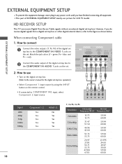
... COMPONENT IN2 input, select Component 2 input source. operation) I Select Component 1 input source by using the INPUT button on the remote control. 1 2 I This part of the digital set top box to the COMPONENT IN VIDEO 1 jacks on the set -top box.... HD RECEIVER SETUP This TV can receive Digital Over-the-air/Cable signals without an external digital set . VIDEO AUDIO S-V ( /DVI IN 2. Match the jack colors ...24.00 29.97 30.00 59.94 60.00 18 How to the owner's manual for LCD TV model.
... COMPONENT IN2 input, select Component 2 input source. operation) I Select Component 1 input source by using the INPUT button on the remote control. 1 2 I This part of the digital set top box to the COMPONENT IN VIDEO 1 jacks on the set -top box.... HD RECEIVER SETUP This TV can receive Digital Over-the-air/Cable signals without an external digital set . VIDEO AUDIO S-V ( /DVI IN 2. Match the jack colors ...24.00 29.97 30.00 59.94 60.00 18 How to the owner's manual for LCD TV model.
Owner's Manual (English)
Page 21
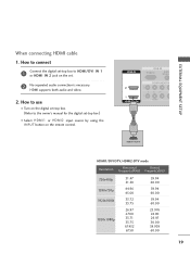
... HDMI/DVI IN 1 or HDMI IN 2 jack on the set -top box.) I Select HDMI1 or HDMI2 input source by using the INPUT button on the remote control. HDMI IN RGB IN RGB(PC) AUDIO (RGB/D 2 2 1 1 HDMI/DVI IN COMPONENT IN VIDEO 1 HDMI-DTV OUTPUT HDMI1/DVI-DTV, HDMI2-DTV mode Resolution...
... HDMI/DVI IN 1 or HDMI IN 2 jack on the set -top box.) I Select HDMI1 or HDMI2 input source by using the INPUT button on the remote control. HDMI IN RGB IN RGB(PC) AUDIO (RGB/D 2 2 1 1 HDMI/DVI IN COMPONENT IN VIDEO 1 HDMI-DTV OUTPUT HDMI1/DVI-DTV, HDMI2-DTV mode Resolution...

Owner's Manual (English)
Page 22
EXTERNAL EQUIPMENT SETUP EXTERNAL EQUIPMENT SETUP When connecting HDMI to the AUDIO (RGB/DVI) jack on the remote control. 20 How to use I Turn on the digital set-top box. (Refer to the owner's manual for the digital set-top box.) I Select HDMI1 ... source by using the INPUT button on the set -top box to DVI cable HDMI IN ANTENNA/ CABLE IN RGB IN DIGITAL RGB(PC) AUDIO REMOTE AUDIO OUT (RGB/DVI) SERVICE CONTROL IN OPTICAL 2 2 1 1 HDMI/DVI IN COMPONENT IN RS-232C IN (CONTROL & SERVICE) AUDIO OUT VIDEO AUDIO S-VIDEO VIDEO (MONO...
EXTERNAL EQUIPMENT SETUP EXTERNAL EQUIPMENT SETUP When connecting HDMI to the AUDIO (RGB/DVI) jack on the remote control. 20 How to use I Turn on the digital set-top box. (Refer to the owner's manual for the digital set-top box.) I Select HDMI1 ... source by using the INPUT button on the set -top box to DVI cable HDMI IN ANTENNA/ CABLE IN RGB IN DIGITAL RGB(PC) AUDIO REMOTE AUDIO OUT (RGB/DVI) SERVICE CONTROL IN OPTICAL 2 2 1 1 HDMI/DVI IN COMPONENT IN RS-232C IN (CONTROL & SERVICE) AUDIO OUT VIDEO AUDIO S-VIDEO VIDEO (MONO...
Owner's Manual (English)
Page 23
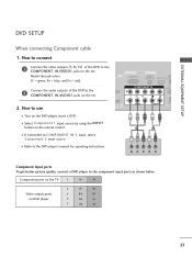
...IN AUDIO1 jacks on DVD player Y PB PR Y B-Y R-Y Y Cb Cr Y Pb Pr 21 How to the COMPONENT IN VIDEO1 jacks on the remote control. Y PB PR L R Component Input ports To get better picture quality, connect a DVD player to the DVD player's manual for operating instructions.... Component ports on the TV Y PB PR Video output ports on the set . I Refer to the component input ports as shown below. COMPONENT IN 2 RS (CONTR 2. I...
...IN AUDIO1 jacks on DVD player Y PB PR Y B-Y R-Y Y Cb Cr Y Pb Pr 21 How to the COMPONENT IN VIDEO1 jacks on the remote control. Y PB PR L R Component Input ports To get better picture quality, connect a DVD player to the DVD player's manual for operating instructions.... Component ports on the TV Y PB PR Video output ports on the set . I Refer to the component input ports as shown below. COMPONENT IN 2 RS (CONTR 2. I...

Owner's Manual (English)
Page 24
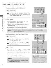
...IN 1 or HDMI IN 2 jack on the set . 2 No separated audio connection is necessary. I Select A V 1 input source by using the INPUT button on the remote control. HDMI suppo( rt)s both audio and video. 2. HDMI IN RGB IN RGB(PC) AUDIO (RGB/DVI 2 2 1 1 HDMI/DVI IN COMPONENT IN VIDEO A...to the DVD player's manual for operating instructions. How to use I Refer to AV IN2, select A V 2 input source. I Turn on the remote control. How to use I If connected to the DVD player's manual for operating instructions. S-VIDEO AUDIO L R ANTENNA/ CABLE IN 1 2 DIGITAL IO...
...IN 1 or HDMI IN 2 jack on the set . 2 No separated audio connection is necessary. I Select A V 1 input source by using the INPUT button on the remote control. HDMI suppo( rt)s both audio and video. 2. HDMI IN RGB IN RGB(PC) AUDIO (RGB/DVI 2 2 1 1 HDMI/DVI IN COMPONENT IN VIDEO A...to the DVD player's manual for operating instructions. How to use I Refer to AV IN2, select A V 2 input source. I Turn on the remote control. How to use I If connected to the DVD player's manual for operating instructions. S-VIDEO AUDIO L R ANTENNA/ CABLE IN 1 2 DIGITAL IO...
Owner's Manual (English)
Page 25
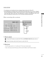
...does not cover the product bearing this phenomenon. the fixed images on the sides of time (Only Plasma TV model). This phenomenon is used; I Set VCR output switch to 3 or 4 and then tune TV to avoid having a fixed image remain on the screen for a long peri- How to connect 1 Connect... visible on the screen. I To avoid picture noise (interference), leave an adequate distance between the VCR and TV. When connecting with an antenna ANTENNA/ CABLE IN GB IN DIGITAL AUDIO REMOTE AUDIO OUT (RGB/DVI) SERVICE CONTROL IN OPTICAL MPONENT IN RS-232C IN (CONTROL & SERVICE) AUDIO OUT...
...does not cover the product bearing this phenomenon. the fixed images on the sides of time (Only Plasma TV model). This phenomenon is used; I Set VCR output switch to 3 or 4 and then tune TV to avoid having a fixed image remain on the screen for a long peri- How to connect 1 Connect... visible on the screen. I To avoid picture noise (interference), leave an adequate distance between the VCR and TV. When connecting with an antenna ANTENNA/ CABLE IN GB IN DIGITAL AUDIO REMOTE AUDIO OUT (RGB/DVI) SERVICE CONTROL IN OPTICAL MPONENT IN RS-232C IN (CONTROL & SERVICE) AUDIO OUT...
Owner's Manual (English)
Page 26
...A V 2 input source. ! In the event that you have a mono VCR, connect the audio cable from the VCR to connect 1 Connect the AUDIO/VIDEO jacks between TV and VCR. I If connected to AV IN2, select A V 2 input source. How to use I Select A V 1 input source by using the INPUT button on ... PLAY on the VCR. (Refer to the S -VIDEO input on the set . ANT IN S-VIDEO VIDEO L R ANT OUT OUTPUT SWITCH 1 ANTENNA/ CABLE IN DIGITAL UDIO REMOTE AUDIO OUT B/DVI) SERVICE CONTROL IN OPTICAL T IN RS-232C IN (CONTROL & SERVICE) ( ) AUDIO OUT AUDIO S-VIDEO VIDEO (MONO) AUDIO AV IN 1 ! ( ...
...A V 2 input source. ! In the event that you have a mono VCR, connect the audio cable from the VCR to connect 1 Connect the AUDIO/VIDEO jacks between TV and VCR. I If connected to AV IN2, select A V 2 input source. How to use I Select A V 1 input source by using the INPUT button on ... PLAY on the VCR. (Refer to the S -VIDEO input on the set . ANT IN S-VIDEO VIDEO L R ANT OUT OUTPUT SWITCH 1 ANTENNA/ CABLE IN DIGITAL UDIO REMOTE AUDIO OUT B/DVI) SERVICE CONTROL IN OPTICAL T IN RS-232C IN (CONTROL & SERVICE) ( ) AUDIO OUT AUDIO S-VIDEO VIDEO (MONO) AUDIO AV IN 1 ! ( ...

Owner's Manual (English)
Page 27
VIDEO L/MONO AUDIO R Camcorder Video Game Set VIDEO L R S-VIDEO 1 AV IN 2 25 Match the jack colors. (Video = yellow, Audio Left = white, and Audio Right = red) 2. I Select A V 2 input source by using the INPUT button on the remote control. How to use I If connected to connect 1 Connect the AUDIO/VIDEO jacks between TV and external equipment. How to AV IN1 input, select A V 1 input source. EXTERNAL EQUIPMENT SETUP OTHER A/V SOURCE SETUP 1. I Operate the corresponding external equipment.
VIDEO L/MONO AUDIO R Camcorder Video Game Set VIDEO L R S-VIDEO 1 AV IN 2 25 Match the jack colors. (Video = yellow, Audio Left = white, and Audio Right = red) 2. I Select A V 2 input source by using the INPUT button on the remote control. How to use I If connected to connect 1 Connect the AUDIO/VIDEO jacks between TV and external equipment. How to AV IN1 input, select A V 1 input source. EXTERNAL EQUIPMENT SETUP OTHER A/V SOURCE SETUP 1. I Operate the corresponding external equipment.

Owner's Manual (English)
Page 28
... OUTPUT AUDIO 26 When connecting D-sub 15 pin cable 1. How to the TV's settings. I Select RGB-PC input source by using the INPUT button on the PC and the TV. EXTERNAL EQUIPMENT SETUP EXTERNAL EQUIPMENT SETUP PC SETUP This TV provides Plug and Play capability, meaning that the PC adjusts automatically to use...
... OUTPUT AUDIO 26 When connecting D-sub 15 pin cable 1. How to the TV's settings. I Select RGB-PC input source by using the INPUT button on the PC and the TV. EXTERNAL EQUIPMENT SETUP EXTERNAL EQUIPMENT SETUP PC SETUP This TV provides Plug and Play capability, meaning that the PC adjusts automatically to use...

Owner's Manual (English)
Page 29
.../DVI IN 1 jack on the set . 2. AV IN 1 EXTERNAL EQUIPMENT SETUP When connecting HDMI to the AUDIO (RGB/DVI) jack on the PC and the TV. How to connect 1 Connect the DVI output of the PC to use I Select HDMI1 input source by using the INPUT button on the.... 27 I Turn on the set . 2 Connect the PC audio output to DVI cable CABLE IN HDMI IN RGB IN DIGITAL RGB(PC) AUDIO REMOTE AUDIO OUT (RGB/DVI) SERVICE CONTROL IN OPTICAL 2 2 1 1 HDMI/DVI IN COMPONENT IN RS-232C IN (CONTROL & SERVICE) AUDIO OUT VIDEO AUDIO S-VIDEO VIDEO (MONO) ...
.../DVI IN 1 jack on the set . 2. AV IN 1 EXTERNAL EQUIPMENT SETUP When connecting HDMI to the AUDIO (RGB/DVI) jack on the PC and the TV. How to connect 1 Connect the DVI output of the PC to use I Select HDMI1 input source by using the INPUT button on the.... 27 I Turn on the set . 2 Connect the PC audio output to DVI cable CABLE IN HDMI IN RGB IN DIGITAL RGB(PC) AUDIO REMOTE AUDIO OUT (RGB/DVI) SERVICE CONTROL IN OPTICAL 2 2 1 1 HDMI/DVI IN COMPONENT IN RS-232C IN (CONTROL & SERVICE) AUDIO OUT VIDEO AUDIO S-VIDEO VIDEO (MONO) ...

Owner's Manual (English)
Page 31
... to a PC Output, Select RGB-PC with using the INPUT button on the screen background. For Plasma TV Resolution Position Size 1024 x 768 1280 x 768 1360 x 768 Phase Reset D MENU Prev E Select Ok For LCD TV Resolution Position Size Phase 1024 x 768 1280 x 768 1360 x 768 1366 x 768 Reset D MENU ...G button to left/right and up/down as you prefer. Position This function is connected to remove any vertical bars or stripes visible on the remote control. PICTURE SOUND SAP CC ADJUST EXTERNAL EQUIPMENT SETUP Adjustment for PC mode Overview When the RGB input of XGA/WXGA.
... to a PC Output, Select RGB-PC with using the INPUT button on the screen background. For Plasma TV Resolution Position Size 1024 x 768 1280 x 768 1360 x 768 Phase Reset D MENU Prev E Select Ok For LCD TV Resolution Position Size Phase 1024 x 768 1280 x 768 1360 x 768 1366 x 768 Reset D MENU ...G button to left/right and up/down as you prefer. Position This function is connected to remove any vertical bars or stripes visible on the remote control. PICTURE SOUND SAP CC ADJUST EXTERNAL EQUIPMENT SETUP Adjustment for PC mode Overview When the RGB input of XGA/WXGA.

Owner's Manual (English)
Page 33
...Connect audio outputs to external audio equipment via the Audio Output port. EXTERNAL EQUIPMENT SETUP AUDIO OUT SETUP Send the TV's audio to the TV's AUDIO OUT jacks. 2 Set the "TV Speaker option - Looking at the laser beam may damage your vision. How to connect S-VIDEO VIDEO (MONO) ... the SPDIF out (optical) about the contents with external audio equipments, such as amplifiers or speakers, please turn the TV speakers off. (G p.59) ANTENNA/ CABLE IN DIGITAL O REMOTE AUDIO OUT VI) SERVICE CONTROL IN OPTICAL N RS-232C IN 1 (CONTROL & SERVICE) AUDIO OUT AUDIO S-VIDEO ...
...Connect audio outputs to external audio equipment via the Audio Output port. EXTERNAL EQUIPMENT SETUP AUDIO OUT SETUP Send the TV's audio to the TV's AUDIO OUT jacks. 2 Set the "TV Speaker option - Looking at the laser beam may damage your vision. How to connect S-VIDEO VIDEO (MONO) ... the SPDIF out (optical) about the contents with external audio equipments, such as amplifiers or speakers, please turn the TV speakers off. (G p.59) ANTENNA/ CABLE IN DIGITAL O REMOTE AUDIO OUT VI) SERVICE CONTROL IN OPTICAL N RS-232C IN 1 (CONTROL & SERVICE) AUDIO OUT AUDIO S-VIDEO ...

Owner's Manual (English)
Page 34
... EXIT TIMER RATIO SIMPLINK VOL MUTE FAV CH 1 2 3 4 5 6 7 8 9 0 BACK 32 MODE Select the remote's operating mode. BRIGHT -/ + Adjust the brightness on -screen displays and return to TV viewing from any menu. EXIT Clear all on screen. G p.70 RATIO Change the aspect ratio. G p.41 VOLUME UP Increase...the on or off automatically. TIMER Select the amount of AV devices connected to your TV turns off . When you toggle this button, the SimpLink menu appears at the remote control sensor on the TV. BACK Tune to enter a program number for multiple program channels such as 2-1, 2-2,...
... EXIT TIMER RATIO SIMPLINK VOL MUTE FAV CH 1 2 3 4 5 6 7 8 9 0 BACK 32 MODE Select the remote's operating mode. BRIGHT -/ + Adjust the brightness on -screen displays and return to TV viewing from any menu. EXIT Clear all on screen. G p.70 RATIO Change the aspect ratio. G p.41 VOLUME UP Increase...the on or off automatically. TIMER Select the amount of AV devices connected to your TV turns off . When you toggle this button, the SimpLink menu appears at the remote control sensor on the TV. BACK Tune to enter a program number for multiple program channels such as 2-1, 2-2,...


