
3275 Manual
Page 2
... and signal word review 2 Preparing your garage door 3 Tools needed 3 Planning 4 Carton inventory 5 Installation hardware 5 Assembly 6-7 Attach the rail to the motor unit 6 Attach the chain spreader 6 Tighten the chain 7 Installation 7-22 Installation safety instructions 7 Determine the header bracket location... 8 Install the header bracket 9 Attach the rail to the header bracket 10 Position the opener 10 Hang the opener 11 Install the door control 12 Install the light 13...
... and signal word review 2 Preparing your garage door 3 Tools needed 3 Planning 4 Carton inventory 5 Installation hardware 5 Assembly 6-7 Attach the rail to the motor unit 6 Attach the chain spreader 6 Tighten the chain 7 Installation 7-22 Installation safety instructions 7 Determine the header bracket location... 8 Install the header bracket 9 Attach the rail to the header bracket 10 Position the opener 10 Hang the opener 11 Install the door control 12 Install the light 13...
3275 Manual
Page 5
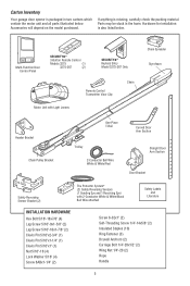
... also listed below . Multi-Function Door Control Panel SECURITY✚® 3-Button Remote Control Models 3275 (1) 3275-267 (2) SECURITY✚® Keyless Entry Model 3275-267 Only Remote Control Transmitter Visor Clip Chain Motor Unit with Light Lenses Chain Spreader Styrofoam Header ...Bracket Chain Pulley Bracket One-Piece T-Rail Curved Door Arm Section Trolley 2-Conductor Bell Wire White & White/...
... also listed below . Multi-Function Door Control Panel SECURITY✚® 3-Button Remote Control Models 3275 (1) 3275-267 (2) SECURITY✚® Keyless Entry Model 3275-267 Only Remote Control Transmitter Visor Clip Chain Motor Unit with Light Lenses Chain Spreader Styrofoam Header ...Bracket Chain Pulley Bracket One-Piece T-Rail Curved Door Arm Section Trolley 2-Conductor Bell Wire White & White/...
3275 Manual
Page 6
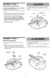
...and align the back hole with the washered bolt and lock nut previously removed. Chain Spreader Motor Unit Sprocket 6 ASSEMBLY STEP 1 Attach the Rail to the Motor Unit To avoid installation difficulties, do not run the garage door opener until instructed to do so. • ...Spreader Motor Unit Sprocket To avoid possible SERIOUS INJURY to use ONLY those bolts/fasteners mounted in the top of the unit. • Fasten rail with the hole in the top of sprocket while operating opener. • Securely attach chain spreader BEFORE operating. Tighten securely. Remember to fi...
...and align the back hole with the washered bolt and lock nut previously removed. Chain Spreader Motor Unit Sprocket 6 ASSEMBLY STEP 1 Attach the Rail to the Motor Unit To avoid installation difficulties, do not run the garage door opener until instructed to do so. • ...Spreader Motor Unit Sprocket To avoid possible SERIOUS INJURY to use ONLY those bolts/fasteners mounted in the top of the unit. • Fasten rail with the hole in the top of sprocket while operating opener. • Securely attach chain spreader BEFORE operating. Tighten securely. Remember to fi...
3275 Manual
Page 7
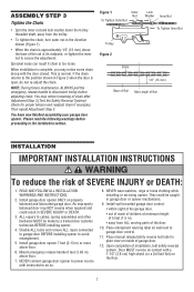
...Figure 1). Install wall-mounted garage door control: • within sight of the garage door. • out of reach of Rail adjusting chain. Place entrapment warning label on wall next to disconnect trolley before proceeding to cables, spring assemblies and other hardware MUST ...;oor. 6. Mid Length of chain after Adjustment Step 3 (Test the Safety Reversal System). An improperly balanced door may notice loosening of Rail You have now finished assembling your garage door opener. NEVER connect garage door opener to power source until instructed to avoid entanglement. ...
...Figure 1). Install wall-mounted garage door control: • within sight of the garage door. • out of reach of Rail adjusting chain. Place entrapment warning label on wall next to disconnect trolley before proceeding to cables, spring assemblies and other hardware MUST ...;oor. 6. Mid Length of chain after Adjustment Step 3 (Test the Safety Reversal System). An improperly balanced door may notice loosening of Rail You have now finished assembling your garage door opener. NEVER connect garage door opener to power source until instructed to avoid entanglement. ...
3275 Manual
Page 10
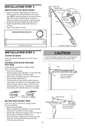
... need help at is convenient for setting an ideal door-to disconnect inner and outer sections. INSTALLATION STEP 3 Attach the Rail to your door type as illustrated. HARDWARE SHOWN ACTUAL SIZE Ring Fastener Header Wall Header Bracket Chain Pulley Bracket Header Bracket ...Ring Fastener Clevis Pin 5/16"x2-3/4" Rail Chain Pulley Bracket Rail Garage Door Clevis Pin 5/16"x2-3/4" Temporary Support INSTALLATION STEP 4 Position the Opener Follow instructions which apply to the ...
... need help at is convenient for setting an ideal door-to disconnect inner and outer sections. INSTALLATION STEP 3 Attach the Rail to your door type as illustrated. HARDWARE SHOWN ACTUAL SIZE Ring Fastener Header Wall Header Bracket Chain Pulley Bracket Header Bracket ...Ring Fastener Clevis Pin 5/16"x2-3/4" Rail Chain Pulley Bracket Rail Garage Door Clevis Pin 5/16"x2-3/4" Temporary Support INSTALLATION STEP 4 Position the Opener Follow instructions which apply to the ...
3275 Manual
Page 11
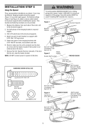
...if the bracket is not centered above the door). 7. Check to opener at this time. NOTE: DO NOT connect power to make sure the rail is centered over the door (or in the structural supports. 4. Figure 1 Structural Supports Measure Distance Lag Screws 5/16"-18x1-7/8" Bolt 5/16"-...brackets should be angled (Figure 1) to the hanging brackets with 5/16"-18x1-7/8" lag screws. 5. Remove the 2x4. If the door hits the rail, raise the header bracket. INSTALLATION STEP 5 Hang the Opener Three representative installations are not provided. 1. Cut both pieces of the hanging bracket to...
...if the bracket is not centered above the door). 7. Check to opener at this time. NOTE: DO NOT connect power to make sure the rail is centered over the door (or in the structural supports. 4. Figure 1 Structural Supports Measure Distance Lag Screws 5/16"-18x1-7/8" Bolt 5/16"-...brackets should be angled (Figure 1) to the hanging brackets with 5/16"-18x1-7/8" lag screws. 5. Remove the 2x4. If the door hits the rail, raise the header bracket. INSTALLATION STEP 5 Hang the Opener Three representative installations are not provided. 1. Cut both pieces of the hanging bracket to...
3275 Manual
Page 28
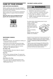
Pages 23 and 24 refer to the rail. Only a screwdriver is unbalanced or binding, call a trained door systems technician. • Check to the following two conditions: (1) this device may not cause harmful interference, ... 100° C (212° F) or incinerate. Make any adjustment of old battery properly. Tested to wipe away the existing grease from the garage door opener rail. Disconnect trolley first. Do not grease the door tracks. Battery positive side up (+). CARE OF YOUR OPENER LIMIT AND FORCE ADJUSTMENTS: Weather conditions may...
Pages 23 and 24 refer to the rail. Only a screwdriver is unbalanced or binding, call a trained door systems technician. • Check to the following two conditions: (1) this device may not cause harmful interference, ... 100° C (212° F) or incinerate. Make any adjustment of old battery properly. Tested to wipe away the existing grease from the garage door opener rail. Disconnect trolley first. Do not grease the door tracks. Battery positive side up (+). CARE OF YOUR OPENER LIMIT AND FORCE ADJUSTMENTS: Weather conditions may...
3275 Manual
Page 29
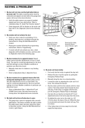
.... • Run the motor unit from the opener by turning down direction. • Verify the safety sensors are properly installed, aligned and free of the rail. (When the door is reconnected and closed position. • Loosen the chain by turning the UP Travel adjustment screw 2 full turns away from the arrow...
.... • Run the motor unit from the opener by turning down direction. • Verify the safety sensors are properly installed, aligned and free of the rail. (When the door is reconnected and closed position. • Loosen the chain by turning the UP Travel adjustment screw 2 full turns away from the arrow...

3275 Manual
Page 33
... 1710LM DESCRIPTION Master link kit Chain pulley bracket Complete trolley assembly One-piece rail for 7' (2.1 m) door Full chain assembly Rail grease NOT SHOWN One-piece rail for 8' (2.4 m) door One-piece rail for 10' (3 m) door 2 10 9 KEY PART NO. NO. REPAIR PARTS Rail Assembly Parts 5 1 4 3 2 Installation Parts 13 6 5 8 12 11 6 4 KEY PART NO. Spanish 33 DESCRIPTION...
... 1710LM DESCRIPTION Master link kit Chain pulley bracket Complete trolley assembly One-piece rail for 7' (2.1 m) door Full chain assembly Rail grease NOT SHOWN One-piece rail for 8' (2.4 m) door One-piece rail for 10' (3 m) door 2 10 9 KEY PART NO. NO. REPAIR PARTS Rail Assembly Parts 5 1 4 3 2 Installation Parts 13 6 5 8 12 11 6 4 KEY PART NO. Spanish 33 DESCRIPTION...


