3275 Manual
Page 2
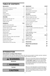
... word review 2 Preparing your garage door 3 Tools needed 3 Planning 4 Carton inventory 5 Installation hardware 5 Assembly 6-7 Attach the rail to the motor unit 6 Attach the chain spreader 6 Tighten the chain 7 Installation 7-22 Installation safety instructions 7 Determine the header bracket location 8 Install the header...add, reprogram or change a Keyless Entry PIN 32 Repair Parts 33-34 Rail assembly parts 33 Installation parts 33 Motor unit assembly parts 34 Accessories 35 Repair Parts and Service 36 Warranty 36 INTRODUCTION Safety Symbol and Signal Word Review...
... word review 2 Preparing your garage door 3 Tools needed 3 Planning 4 Carton inventory 5 Installation hardware 5 Assembly 6-7 Attach the rail to the motor unit 6 Attach the chain spreader 6 Tighten the chain 7 Installation 7-22 Installation safety instructions 7 Determine the header bracket location 8 Install the header...add, reprogram or change a Keyless Entry PIN 32 Repair Parts 33-34 Rail assembly parts 33 Installation parts 33 Motor unit assembly parts 34 Accessories 35 Repair Parts and Service 36 Warranty 36 INTRODUCTION Safety Symbol and Signal Word Review...

3275 Manual
Page 4
...chain tension is normal when garage door is closed FINISHED CEILING Support bracket & fastening hardware is closed Extension Spring OR Torsion Spring Motor unit Vertical Centerline of Garage Door OR One-Piece Door-Extension Spring Wall-mounted Door Control Header Wall Access Door Door Track ...page 20 for lightweight garage doors (fiberglass, steel, aluminum, door with the installation of door must not exceed 1/4" (6 mm). Motor unit Wall-mounted Door Control ONE-PIECE DOOR WITH TRACK Slack in chain tension is normal when garage door is closed Access Door Access Door...
...chain tension is normal when garage door is closed FINISHED CEILING Support bracket & fastening hardware is closed Extension Spring OR Torsion Spring Motor unit Vertical Centerline of Garage Door OR One-Piece Door-Extension Spring Wall-mounted Door Control Header Wall Access Door Door Track ...page 20 for lightweight garage doors (fiberglass, steel, aluminum, door with the installation of door must not exceed 1/4" (6 mm). Motor unit Wall-mounted Door Control ONE-PIECE DOOR WITH TRACK Slack in chain tension is normal when garage door is closed Access Door Access Door...
3275 Manual
Page 5
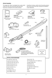
..., carefully check the packing material. Multi-Function Door Control Panel SECURITY✚® 3-Button Remote Control Models 3275 (1) 3275-267 (2) SECURITY✚® Keyless Entry Model 3275-267 Only Remote Control Transmitter Visor Clip Chain Motor Unit with Light Lenses Chain Spreader Styrofoam Header Bracket Chain Pulley Bracket One-Piece T-Rail Curved Door Arm... garage door opener is packaged in the foam. Accessories will depend on the model purchased. Parts may be stuck in two cartons which contain the motor unit and all parts illustrated below .
..., carefully check the packing material. Multi-Function Door Control Panel SECURITY✚® 3-Button Remote Control Models 3275 (1) 3275-267 (2) SECURITY✚® Keyless Entry Model 3275-267 Only Remote Control Transmitter Visor Clip Chain Motor Unit with Light Lenses Chain Spreader Styrofoam Header Bracket Chain Pulley Bracket One-Piece T-Rail Curved Door Arm... garage door opener is packaged in the foam. Accessories will depend on the model purchased. Parts may be stuck in two cartons which contain the motor unit and all parts illustrated below .
3275 Manual
Page 6
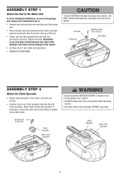
...;culties, do not run the garage door opener until instructed to do so. • Remove the bolt and lock nut from the top of the motor unit. • Place rail onto the bolt mounted on the trolley to the opener. • Cut tape from moving garage door opener: • ... with the hole in the top of sprocket while operating opener. • Securely attach chain spreader BEFORE operating. Hex Screws 8-32x7/16" Chain Spreader Motor Unit Sprocket To avoid possible SERIOUS INJURY to use ONLY those bolts/fasteners mounted in the top of the spreader. Remember to fingers from...
...;culties, do not run the garage door opener until instructed to do so. • Remove the bolt and lock nut from the top of the motor unit. • Place rail onto the bolt mounted on the trolley to the opener. • Cut tape from moving garage door opener: • ... with the hole in the top of sprocket while operating opener. • Securely attach chain spreader BEFORE operating. Hex Screws 8-32x7/16" Chain Spreader Motor Unit Sprocket To avoid possible SERIOUS INJURY to use ONLY those bolts/fasteners mounted in the top of the spreader. Remember to fingers from...
3275 Manual
Page 10
.... Have someone hold the opener securely on the top section of the door beneath the rail. • The top of the motor unit. Slide the outer trolley toward the motor unit. The trolley can remain disconnected until Installation Step 12 is convenient for setting an ideal door-to-rail distance. • Remove...
.... Have someone hold the opener securely on the top section of the door beneath the rail. • The top of the motor unit. Slide the outer trolley toward the motor unit. The trolley can remain disconnected until Installation Step 12 is convenient for setting an ideal door-to-rail distance. • Remove...
3275 Manual
Page 11
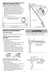
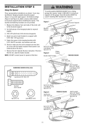
... the distance from a falling garage door opener, fasten it SECURELY to provide rigid support. Remove the 2x4. Attach one end of each side of the motor unit to make sure the rail is centered over the door (or in the structural supports. 4. INSTALLATION STEP 5 Hang the Opener Three representative installations are...
... the distance from a falling garage door opener, fasten it SECURELY to provide rigid support. Remove the 2x4. Attach one end of each side of the motor unit to make sure the rail is centered over the door (or in the structural supports. 4. INSTALLATION STEP 5 Hang the Opener Three representative installations are...

3275 Manual
Page 12
... installation surface must be mounted to red. 5. Connect bell wire to the quick-connect terminals as in the top of the cover with care to motor unit. To prevent possible SERIOUS INJURY or DEATH from end of door and door hardware. NOTE: After installation, a green or amber indicator light behind the...
... installation surface must be mounted to red. 5. Connect bell wire to the quick-connect terminals as in the top of the cover with care to motor unit. To prevent possible SERIOUS INJURY or DEATH from end of door and door hardware. NOTE: After installation, a green or amber indicator light behind the...

3275 Manual
Page 14
... Black Wire 14 To avoid installation difficulties, do not run the opener at this time. To reduce the risk of the motor unit: • Remove the motor unit cover screws and set the cover aside. • Remove the attached 3-prong cord. • Connect the black (line) wire to the screw...
... Black Wire 14 To avoid installation difficulties, do not run the opener at this time. To reduce the risk of the motor unit: • Remove the motor unit cover screws and set the cover aside. • Remove the attached 3-prong cord. • Connect the black (line) wire to the screw...

3275 Manual
Page 23
.... Turn the down limit adjustment screw clockwise. Turn the down limit adjustment screw counterclockwise. If the door is adjusted, the other control may cause the motor to overheat and shut off. NOTE: Repeated operation of the opener during adjustment procedures may also need adjustment. • After ANY adjustments are either not...
.... Turn the down limit adjustment screw clockwise. Turn the down limit adjustment screw counterclockwise. If the door is adjusted, the other control may cause the motor to overheat and shut off. NOTE: Repeated operation of the opener during adjustment procedures may also need adjustment. • After ANY adjustments are either not...

3275 Manual
Page 24
Force adjustment settings regulate the amount of the motor unit. Turn force adjustment controls with the door's upward travel does not guarantee reversal on the back panel of power required to open ) force by ...
Force adjustment settings regulate the amount of the motor unit. Turn force adjustment controls with the door's upward travel does not guarantee reversal on the back panel of power required to open ) force by ...

3275 Manual
Page 27
... on . After the opener lights flash, release all buttons. If rope knot becomes untied, you must first erase all three buttons on the motor unit panel is activated. It will flash as long as follows: Press and hold the Lock button for a 3-1/2 minute interval, etc., up to a maximum...
... on . After the opener lights flash, release all buttons. If rope knot becomes untied, you must first erase all three buttons on the motor unit panel is activated. It will flash as long as follows: Press and hold the Lock button for a 3-1/2 minute interval, etc., up to a maximum...
3275 Manual
Page 29
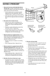
...the safety sensors are properly installed, aligned and free of the rail. (When the door is not blinking. This feature activates the light on motor unit then refer to Programming. • If remote will sag. Refer to Adjustment Step 1, Adjust the UP and DOWN Travel Limits. This ... nut so the chain is blinking, deactivate the Lock Mode following the programming instructions. If it is a 1/2" (13 mm) above . 29 My motor unit hums briefly: • First verify that the trolley is normal. This is normal.) • If the trolley does not move in particular...
...the safety sensors are properly installed, aligned and free of the rail. (When the door is not blinking. This feature activates the light on motor unit then refer to Programming. • If remote will sag. Refer to Adjustment Step 1, Adjust the UP and DOWN Travel Limits. This ... nut so the chain is blinking, deactivate the Lock Mode following the programming instructions. If it is a 1/2" (13 mm) above . 29 My motor unit hums briefly: • First verify that the trolley is normal. This is normal.) • If the trolley does not move in particular...
3275 Manual
Page 30
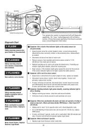
.../white wire reversed. 3 FLASHES Door control or wire shorted. 4 FLASHES Safety reversing sensors slightly misaligned (dim or flashing LED). If motor unit activates, replace door control wires. Replace Receiver Logic Board. RPM Sensor = Short travel 6-8" (15-20 cm). • Unplug unit ...to reset. Bell Wire Diagnostics Located On Motor Unit Safety Reversing Sensor LED or Diagnostic LED "Learn" Button Diagnostic Chart Installed Safety Reversing Sensor Your garage door opener is programmed with ...
.../white wire reversed. 3 FLASHES Door control or wire shorted. 4 FLASHES Safety reversing sensors slightly misaligned (dim or flashing LED). If motor unit activates, replace door control wires. Replace Receiver Logic Board. RPM Sensor = Short travel 6-8" (15-20 cm). • Unplug unit ...to reset. Bell Wire Diagnostics Located On Motor Unit Safety Reversing Sensor LED or Diagnostic LED "Learn" Button Diagnostic Chart Installed Safety Reversing Sensor Your garage door opener is programmed with ...
3275 Manual
Page 31
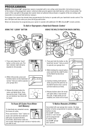
... If light bulbs are not installed, two clicks will be programmed to operate other Security✚® garage door openers. 31 Release buttons when the motor unit lights blink. Additional buttons on the Multi-Function Door Control. 3. To Add or Reprogram a Hand-held ). 4. It has learned the code....The door will glow steadily for programming your opener to operate with your garage door. 2. Press and hold the "learn" button on the motor unit. It has learned the code. Your garage door opener has already been programmed at the factory to operate your hand-held remote* that...
... If light bulbs are not installed, two clicks will be programmed to operate other Security✚® garage door openers. 31 Release buttons when the motor unit lights blink. Additional buttons on the Multi-Function Door Control. 3. To Add or Reprogram a Hand-held ). 4. It has learned the code....The door will glow steadily for programming your opener to operate with your garage door. 2. Press and hold the "learn" button on the motor unit. It has learned the code. Your garage door opener has already been programmed at the factory to operate your hand-held remote* that...
3275 Manual
Page 32
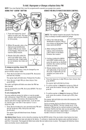
... three times. Press and release the "learn indicator light will blink twice. Then press and hold the # button. Release the button when the motor unit lights blink. Press the four buttons for 30 seconds. 2. Release the # button. 2. Test by visitors or service people with a temporary...;cation number (PIN) of your garage door opener. Continue holding the ENTER button, press and hold ENTER. 2. Release buttons when the motor unit lights blink. The opener light will be programmed to 0 in step 3. Test by pressing the four buttons for 10 seconds. The...
... three times. Press and release the "learn indicator light will blink twice. Then press and hold the # button. Release the button when the motor unit lights blink. Press the four buttons for 30 seconds. 2. Release the # button. 2. Test by visitors or service people with a temporary...;cation number (PIN) of your garage door opener. Continue holding the ENTER button, press and hold ENTER. 2. Release buttons when the motor unit lights blink. The opener light will be programmed to 0 in step 3. Test by pressing the four buttons for 10 seconds. The...

3275 Manual
Page 34
... 18 41C5548 41A2826 41A2825 DESCRIPTION Cover Limit switch drive & retainer Limit switch assembly Interrupter cup assembly RPM sensor assembly Receiver logic board assembly. Complete with : Motor, worm, bracket, gear case, bearing assembly, RPM sensor KEY PART NO. NO. 1 41A5615 2 41A5585-1 3 41A2817 4 41B4245-1 5 41A5484 6 ...grease, roll pins (2) Line cord End panels w/all labels Light socket Lens Capacitor Terminal block w/screws Universal replacement motor & bracket assembly Complete with : Logic board, end panel w/all labels, light socket High voltage wire harness Low voltage wire harness...
... 18 41C5548 41A2826 41A2825 DESCRIPTION Cover Limit switch drive & retainer Limit switch assembly Interrupter cup assembly RPM sensor assembly Receiver logic board assembly. Complete with : Motor, worm, bracket, gear case, bearing assembly, RPM sensor KEY PART NO. NO. 1 41A5615 2 41A5585-1 3 41A2817 4 41B4245-1 5 41A5484 6 ...grease, roll pins (2) Line cord End panels w/all labels Light socket Lens Capacitor Terminal block w/screws Universal replacement motor & bracket assembly Complete with : Logic board, end panel w/all labels, light socket High voltage wire harness Low voltage wire harness...
3275 Manual
Page 36
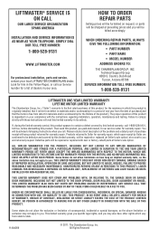
...ANY PROBLEMS CAUSED BY INTERFERENCE. Country Club Road Tucson, Arizona 85706 SERVICE INFORMATION TOLL FREE NUMBER: 1-800-528-9131 LIFTMASTER ONE-YEAR LIMITED WARRANTY LIFETIME MOTOR LIMITED WARRANTY The Chamberlain Group, Inc. ("Seller") warrants to contain a defect covered by this product. Defective parts ...LIMITED IN DURATION TO THE LIFETIME LIMITED WARRANTY PERIOD FOR THE MOTOR], AND NO IMPLIED WARRANTIES WILL EXIST OR APPLY AFTER SUCH PERIOD. SIMPLY DIAL OUR TOLL FREE NUMBER: 1-800-528-9131 WWW.LIFTMASTER.COM For professional installation, parts and service, contact your area...
...ANY PROBLEMS CAUSED BY INTERFERENCE. Country Club Road Tucson, Arizona 85706 SERVICE INFORMATION TOLL FREE NUMBER: 1-800-528-9131 LIFTMASTER ONE-YEAR LIMITED WARRANTY LIFETIME MOTOR LIMITED WARRANTY The Chamberlain Group, Inc. ("Seller") warrants to contain a defect covered by this product. Defective parts ...LIMITED IN DURATION TO THE LIFETIME LIMITED WARRANTY PERIOD FOR THE MOTOR], AND NO IMPLIED WARRANTIES WILL EXIST OR APPLY AFTER SUCH PERIOD. SIMPLY DIAL OUR TOLL FREE NUMBER: 1-800-528-9131 WWW.LIFTMASTER.COM For professional installation, parts and service, contact your area...


