

Product Instruction Manual
Page 9
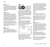
... you must move freely and always spring back to the idle position. immediately stop switch, cutting attachment, deflector and harness. In order to your authorized STIHL dealer for additional information. Such misalignment can cause an improperly tightened fuel filler cap to the closed position (with the cap and the detent on... into the correct position. N If your power tool if it normally. Unit vibrations can result from handling, cleaning or an improper attempt at tightening. The throttle trigger must repeat the above steps. FS 55, FS 55 C, FS 55 R, FS 55 RC 7
... you must move freely and always spring back to the idle position. immediately stop switch, cutting attachment, deflector and harness. In order to your authorized STIHL dealer for additional information. Such misalignment can cause an improperly tightened fuel filler cap to the closed position (with the cap and the detent on... into the correct position. N If your power tool if it normally. Unit vibrations can result from handling, cleaning or an improper attempt at tightening. The throttle trigger must repeat the above steps. FS 55, FS 55 C, FS 55 R, FS 55 RC 7
Product Instruction Manual
Page 10
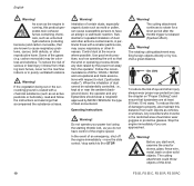
...the type of cutting attachment being used (see the appropriate section of this manual). 8 FS 55, FS 55 C, FS 55 R, FS 55 RC Keep the deflector (and the attached skirt where appropriate) adjusted properly at starting work. For specific starting throttle and allow the engine to slow down to idle. To reduce the risk of Cutting ...to a unit without proper installation of your deflector, handle and / or harness. Warning! Once the engine has started, immediately blip the throttle trigger, which should be absolutely sure that could ignite combustible fumes and cause a fire.
...the type of cutting attachment being used (see the appropriate section of this manual). 8 FS 55, FS 55 C, FS 55 R, FS 55 RC Keep the deflector (and the attached skirt where appropriate) adjusted properly at starting work. For specific starting throttle and allow the engine to slow down to idle. To reduce the risk of Cutting ...to a unit without proper installation of your deflector, handle and / or harness. Warning! Once the engine has started, immediately blip the throttle trigger, which should be absolutely sure that could ignite combustible fumes and cause a fire.
Product Instruction Manual
Page 12
...or other airborne contaminants, in the restricted area should wear a respirator approved by NIOSH / MSHA for a short period after the throttle trigger is released (flywheel effect). When the inhalation of serious or fatal injury / illness from such objects as an active pesticide or herbicide... trade associations with a smaller particle size, may be in particular those with respect to property, also maintain this kind. 10 FS 55, FS 55 C, FS 55 R, FS 55 RC The cutting attachment continues to 0 or STOP. To reduce the risk of dust and other solid objects. In the event of...
...or other airborne contaminants, in the restricted area should wear a respirator approved by NIOSH / MSHA for a short period after the throttle trigger is released (flywheel effect). When the inhalation of serious or fatal injury / illness from such objects as an active pesticide or herbicide... trade associations with a smaller particle size, may be in particular those with respect to property, also maintain this kind. 10 FS 55, FS 55 C, FS 55 R, FS 55 RC The cutting attachment continues to 0 or STOP. To reduce the risk of dust and other solid objects. In the event of...
Product Instruction Manual
Page 20
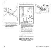
... the handlebar (4) on the drive tube (3) about 6 in the control handle (10). the throttle trigger (11) must point towards the gearbox. Fitting the throttle cable Do not kink the throttle cable or lay it down the screws firmly. 12 N Use the combination wrench or screwdriver to...Mounting the control handle 13 14 14 A 4 3 11 10 8 12 9 4 13 N Push the throttle cable (13) into the retainer (14). make sure the throttle trigger moves freely. 18 FS 55, FS 55 C, FS 55 R, FS 55 RC N Push the control handle onto the handlebar (4) until the holes (12) line up the handlebar and ...
... the handlebar (4) on the drive tube (3) about 6 in the control handle (10). the throttle trigger (11) must point towards the gearbox. Fitting the throttle cable Do not kink the throttle cable or lay it down the screws firmly. 12 N Use the combination wrench or screwdriver to...Mounting the control handle 13 14 14 A 4 3 11 10 8 12 9 4 13 N Push the throttle cable (13) into the retainer (14). make sure the throttle trigger moves freely. 18 FS 55, FS 55 C, FS 55 R, FS 55 RC N Push the control handle onto the handlebar (4) until the holes (12) line up the handlebar and ...
Product Instruction Manual
Page 29
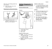
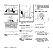
...7 h - N Move the slide control to STOP-0. N Go to "All versions". 002BA312 KN 233BA037 KN 1 1 Throttle trigger lockout 2 Throttle trigger 3 Slide control Positions of the carabiner. 2 English Symbol on the stop symbol and arrow. the ignition is running or can... position has been reached: N Tighten down the screw on - engine off FS 55, FS 55 C, FS 55 R, FS 55 RC 27 Detaching the unit from the harness Starting / Stopping the Engine Version with bike handle Controls 1 1 2 2 6 54 3 7 STOP N Press down the trigger lockout lever and squeeze the throttle trigger.
...7 h - N Move the slide control to STOP-0. N Go to "All versions". 002BA312 KN 233BA037 KN 1 1 Throttle trigger lockout 2 Throttle trigger 3 Slide control Positions of the carabiner. 2 English Symbol on the stop symbol and arrow. the ignition is running or can... position has been reached: N Tighten down the screw on - engine off FS 55, FS 55 C, FS 55 R, FS 55 RC 27 Detaching the unit from the harness Starting / Stopping the Engine Version with bike handle Controls 1 1 2 2 6 54 3 7 STOP N Press down the trigger lockout lever and squeeze the throttle trigger.

Product Instruction Manual
Page 30
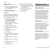
... pump bulb (9) at least five times - This is still cold. English Version with fuel. 28 FS 55, FS 55 C, FS 55 R, FS 55 RC normal run position - the engine can be engaged on the housing. N Press down the throttle trigger lockout and hold it there. N Squeeze the throttle trigger until the catch on the tongue (4) can start - N Set the choke lever (8) to "All...
... pump bulb (9) at least five times - This is still cold. English Version with fuel. 28 FS 55, FS 55 C, FS 55 R, FS 55 RC normal run position - the engine can be engaged on the housing. N Press down the throttle trigger lockout and hold it there. N Squeeze the throttle trigger until the catch on the tongue (4) can start - N Set the choke lever (8) to "All...
Product Instruction Manual
Page 31
...FS 55, FS 55 C, FS 55 R, FS 55 RC 29 it out slowly and steadily. it down firmly - The cutting attachment must rest securely on the drive tube. N Hold the starter grip with your right hand. Do not pull out the starter rope all the way - As soon as the engine runs Version with loop handle N Squeeze the throttle trigger... under the fan housing. Do not stand or kneel on the engine support and the deflector. Version with bike handle N Blip the throttle trigger - Starting English Both versions N Do not let the starter grip snap back. N After no more than five pulls, move the ...
...FS 55, FS 55 C, FS 55 R, FS 55 RC 29 it out slowly and steadily. it down firmly - The cutting attachment must rest securely on the drive tube. N Hold the starter grip with your right hand. Do not pull out the starter rope all the way - As soon as the engine runs Version with loop handle N Squeeze the throttle trigger... under the fan housing. Do not stand or kneel on the engine support and the deflector. Version with bike handle N Blip the throttle trigger - Starting English Both versions N Do not let the starter grip snap back. N After no more than five pulls, move the ...
Product Instruction Manual
Page 32
... slide control in direction of the arrow (h) to STOP-0 or the stop switch to e - N Set the choke lever to the starting throttle position. N Set the slide control, trigger lockout lever and throttle trigger to e . N Move the slide control or stop switch to run until you did not move the choke lever to e quickly enough... high loads during the break-in the engine are greater during the break-in period, the frictional resistances in period. see "Storing the Machine". 30 FS 55, FS 55 C, FS 55 R, FS 55 RC Fuel tank run for the first three tank fillings. see "Spark Plug".
... slide control in direction of the arrow (h) to STOP-0 or the stop switch to e - N Set the choke lever to the starting throttle position. N Set the slide control, trigger lockout lever and throttle trigger to e . N Move the slide control or stop switch to run until you did not move the choke lever to e quickly enough... high loads during the break-in the engine are greater during the break-in period, the frictional resistances in period. see "Storing the Machine". 30 FS 55, FS 55 C, FS 55 R, FS 55 RC Fuel tank run for the first three tank fillings. see "Spark Plug".

Product Instruction Manual
Page 41
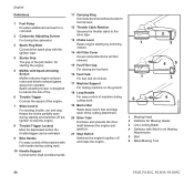
Main Parts 7 6 8 3 1 4 2 5 9 20 11 12 15 13 14 10 16 # 17 18 20 19 11 21 8 6 English 1 Fuel Pump 2 Carburetor Adjusting Screws 3 Spark Plug Boot 4 Starter Grip 5 Muffler with Spark Arresting Screen 6 Throttle Trigger 7 Slide Control 8 Throttle Trigger Lockout 9 Bike Handle 10 Handle Support 11 Carrying Ring 12 Throttle Cable Retainer 13 Choke Lever 14 Air Filter Cover 15 Fuel Filler Cap 16 Fuel Tank 17 Machine Support 18 Loop Handle 19 Barrier Bar 20 Drive Tube 21 Stop Switch # Serial Number 233BA042 KN FS 55, FS 55 C, FS 55 R, FS 55 RC 39
Main Parts 7 6 8 3 1 4 2 5 9 20 11 12 15 13 14 10 16 # 17 18 20 19 11 21 8 6 English 1 Fuel Pump 2 Carburetor Adjusting Screws 3 Spark Plug Boot 4 Starter Grip 5 Muffler with Spark Arresting Screen 6 Throttle Trigger 7 Slide Control 8 Throttle Trigger Lockout 9 Bike Handle 10 Handle Support 11 Carrying Ring 12 Throttle Cable Retainer 13 Choke Lever 14 Air Filter Cover 15 Fuel Filler Cap 16 Fuel Tank 17 Machine Support 18 Loop Handle 19 Barrier Bar 20 Drive Tube 21 Stop Switch # Serial Number 233BA042 KN FS 55, FS 55 C, FS 55 R, FS 55 RC 39
Product Instruction Manual
Page 42
... from operator. Keeps the choke partially open during starting throttle, run and stop the engine. 8 Throttle Trigger Lockout Must be depressed before the throttle trigger can be activated. 9 Bike Handle For easy control...Throttle Trigger Controls the speed of the cutting attachment. 20 Drive Tube Encloses and protects the drive shaft between the engine and gearbox. 21 Stop Switch Switches the engine's ignition off and stops the engine. 2 1 3 45 1 3 6 4 1 Mowing Head 2 Deflector for all Mowing Attachments 5 Skirt 6 Metal Mowing Tool 002BA114 KN 40 FS 55, FS 55 C, FS 55 R, FS 55 RC...
... from operator. Keeps the choke partially open during starting throttle, run and stop the engine. 8 Throttle Trigger Lockout Must be depressed before the throttle trigger can be activated. 9 Bike Handle For easy control...Throttle Trigger Controls the speed of the cutting attachment. 20 Drive Tube Encloses and protects the drive shaft between the engine and gearbox. 21 Stop Switch Switches the engine's ignition off and stops the engine. 2 1 3 45 1 3 6 4 1 Mowing Head 2 Deflector for all Mowing Attachments 5 Skirt 6 Metal Mowing Tool 002BA114 KN 40 FS 55, FS 55 C, FS 55 R, FS 55 RC...


