

User Guide
Page 17
Additionally, The web browser-based Graphical User Interface (GUI), also known as the web configurator, provides easy management of the device and its frequency band is 2.5GHz ~ 2.7GHz; For ... FREQUENCY BAND MAX208M MAX218M MAX208M2W MAX218M2W MAX218M1W MAX218MW MAX318M2W MAX308M MAX318M 2.5 ~ 2.7 GHz 3.4 ~ 3.6 GHz 2.5 ~ 2.7 GHz 3.4 ~ 3.6 GHz 3.4 ~ 3.6 GHz 3.4 ~ 3.6 GHz 3.4 ~ 3.6 GHz 2.5 ~ 2.7 GHz 3.4 ~ 3.6 GHz NUMBER OF PHONE PORTS N/A N/A 2 2 1 N/A 2 N/A N/A WIFI FUNCTION N/A N/A N/A N/A INDOOR OUTDOOR DEVICE DEVICE WiMAX Device Configuration User's Guide 17 Please refer to the...
Additionally, The web browser-based Graphical User Interface (GUI), also known as the web configurator, provides easy management of the device and its frequency band is 2.5GHz ~ 2.7GHz; For ... FREQUENCY BAND MAX208M MAX218M MAX208M2W MAX218M2W MAX218M1W MAX218MW MAX318M2W MAX308M MAX318M 2.5 ~ 2.7 GHz 3.4 ~ 3.6 GHz 2.5 ~ 2.7 GHz 3.4 ~ 3.6 GHz 3.4 ~ 3.6 GHz 3.4 ~ 3.6 GHz 3.4 ~ 3.6 GHz 2.5 ~ 2.7 GHz 3.4 ~ 3.6 GHz NUMBER OF PHONE PORTS N/A N/A 2 2 1 N/A 2 N/A N/A WIFI FUNCTION N/A N/A N/A N/A INDOOR OUTDOOR DEVICE DEVICE WiMAX Device Configuration User's Guide 17 Please refer to the...

User Guide
Page 20
... to the Web Configurator 2.1 Overview The Web Configurator is an HTML-based management interface that supports: HTML 4.0, CSS 2.0, and JavaScript 1.5, and higher. See the Appendix C on page 233 for more information). 2 Launch your device. Enter the default Username (admin) and Password (1234), then click Login. In order to use the Web Configurator you need...
... to the Web Configurator 2.1 Overview The Web Configurator is an HTML-based management interface that supports: HTML 4.0, CSS 2.0, and JavaScript 1.5, and higher. See the Appendix C on page 233 for more information). 2 Launch your device. Enter the default Username (admin) and Password (1234), then click Login. In order to use the Web Configurator you need...

User Guide
Page 51
... IP Address. 4.12.1 Scenario 1 In this scenario, PC A is connected to interface WiMAX and interface IAD for managing the WiMAX Device. PC B is connected directly to bridge mode and then click Save. Figure 16 VLAN Configuration Example 1 A B No VLAN Tag No VLAN Tag Manager IP: No VLAN Tag... LAN: Transparent User Network Transparent CPE No VLAN Tag LAN No VLAN Tag No VLAN Tag PC Manager IP No VLAN Tag Network operators WiMAX Device Configuration User's Guide 51 Chapter...
... IP Address. 4.12.1 Scenario 1 In this scenario, PC A is connected to interface WiMAX and interface IAD for managing the WiMAX Device. PC B is connected directly to bridge mode and then click Save. Figure 16 VLAN Configuration Example 1 A B No VLAN Tag No VLAN Tag Manager IP: No VLAN Tag... LAN: Transparent User Network Transparent CPE No VLAN Tag LAN No VLAN Tag No VLAN Tag PC Manager IP No VLAN Tag Network operators WiMAX Device Configuration User's Guide 51 Chapter...

User Guide
Page 52
... scenario, PC A and PC C are on VLAN 5, while PC B and PC D are on each row. PC D is connected to interface WiMAX and interface IAD for the Filter Setting. Then press OK. 2 Next, configure the Name, VID and Ports for managing the WiMAX Device, through VLAN supporting switch S2. PC A and PC B are recognized...
... scenario, PC A and PC C are on VLAN 5, while PC B and PC D are on each row. PC D is connected to interface WiMAX and interface IAD for the Filter Setting. Then press OK. 2 Next, configure the Name, VID and Ports for managing the WiMAX Device, through VLAN supporting switch S2. PC A and PC B are recognized...

User Guide
Page 53
... received on switch S1 from PC A on the LAN would be tagged to tag the received packets with the appropriate VLAN IDs. Figure 17 VLAN Configuration Example 2 A No VLAN Tag VLAN TagID = 5 S1 VLAN TagID = 5 No VLAN Tag VLAN TagID = 5 S2 C B VLAN TagID = 10 VLAN TagID = 10 No VLAN Tag VLAN... the same as one of the LAN transparent VLAN ID VLAN Tag ID=5 VLAN Tag ID=10 Network operators Router Manager IP VLAN Tag ID=5 1 Configure the Link Type, PVID and Tag/Untag settings for the interfaces as below by clicking each row.
... received on switch S1 from PC A on the LAN would be tagged to tag the received packets with the appropriate VLAN IDs. Figure 17 VLAN Configuration Example 2 A No VLAN Tag VLAN TagID = 5 S1 VLAN TagID = 5 No VLAN Tag VLAN TagID = 5 S2 C B VLAN TagID = 10 VLAN TagID = 10 No VLAN Tag VLAN... the same as one of the LAN transparent VLAN ID VLAN Tag ID=5 VLAN Tag ID=10 Network operators Router Manager IP VLAN Tag ID=5 1 Configure the Link Type, PVID and Tag/Untag settings for the interfaces as below by clicking each row.

User Guide
Page 54
PC A and PC B are connected to interface LAN1 through VLAN supporting switch S2. Interface IAD is configured as an Access port, so tagged packets will be forwarded out of these interfaces from the VLAN supporting switches. VLAN tagged packets will recognize VLAN 5 and VLAN 10 tagged ... 10, and PC E is connected to interface WiMAX through VLAN supporting switch S1. Chapter 4 Tutorials 2 Next, configure the Name, VID and Ports for managing the WiMAX Device. 54 WiMAX Device Configuration User's Guide PC E is on these interfaces. Interfaces LAN1 and WiMAX are Trunk links, so...
PC A and PC B are connected to interface LAN1 through VLAN supporting switch S2. Interface IAD is configured as an Access port, so tagged packets will be forwarded out of these interfaces from the VLAN supporting switches. VLAN tagged packets will recognize VLAN 5 and VLAN 10 tagged ... 10, and PC E is connected to interface WiMAX through VLAN supporting switch S1. Chapter 4 Tutorials 2 Next, configure the Name, VID and Ports for managing the WiMAX Device. 54 WiMAX Device Configuration User's Guide PC E is on these interfaces. Interfaces LAN1 and WiMAX are Trunk links, so...

User Guide
Page 55
...=10 Network operators Router Manager IP VLAN Tag ID=3 VLAN Tag ID=3 1 Configure the Link Type, PVID and Tag/Untag settings for the interfaces as below by clicking each row. WiMAX Device Configuration User's Guide 55 Then press OK. Figure 18 VLAN Configuration Example 3 C VLAN TagID = 5 VLAN TagID = 5 No VLAN Tag A No VLAN Tag... from PC A on the LAN would be tagged to tag the received packets with the appropriate VLAN IDs. Chapter 4 Tutorials Note: You will need to configure the VLAN supporting switches to VLAN 5.
...=10 Network operators Router Manager IP VLAN Tag ID=3 VLAN Tag ID=3 1 Configure the Link Type, PVID and Tag/Untag settings for the interfaces as below by clicking each row. WiMAX Device Configuration User's Guide 55 Then press OK. Figure 18 VLAN Configuration Example 3 C VLAN TagID = 5 VLAN TagID = 5 No VLAN Tag A No VLAN Tag... from PC A on the LAN would be tagged to tag the received packets with the appropriate VLAN IDs. Chapter 4 Tutorials Note: You will need to configure the VLAN supporting switches to VLAN 5.

User Guide
Page 56
... tagged packets will recognize VLAN 5 and VLAN 10 tagged packets it receives on the WiMAX Device, while PC B is connected directly to interface WiMAX and interface IAD for the Filter Setting. Chapter 4 Tutorials 2 Next, configure the Name, VID and Ports for managing the WiMAX Device, through VLAN supporting switch S1. 56 WiMAX Device...
... tagged packets will recognize VLAN 5 and VLAN 10 tagged packets it receives on the WiMAX Device, while PC B is connected directly to interface WiMAX and interface IAD for the Filter Setting. Chapter 4 Tutorials 2 Next, configure the Name, VID and Ports for managing the WiMAX Device, through VLAN supporting switch S1. 56 WiMAX Device...

User Guide
Page 57
... received on switch S1 from PC B on the LAN would be tagged to tag the received packets with the appropriate VLAN IDs. Figure 19 VLAN Configuration Example 4 No VLAN Tag VLAN TagID = 5 A VLAN TagID = 5 S1 No VLAN Tag B User Network No VLAN Tag PC Manager IP: Enable VLAN LAN: Transparent VLAN... Note: Manager IP VLAN ID is the same as the LAN transparent VLAN ID LAN VLAN Tag ID=5 Manager IP VLAN Tag ID=5 Network operators 1 Configure the Link Type, PVID and Tag/Untag settings for the interfaces as below by clicking each row.
... received on switch S1 from PC B on the LAN would be tagged to tag the received packets with the appropriate VLAN IDs. Figure 19 VLAN Configuration Example 4 No VLAN Tag VLAN TagID = 5 A VLAN TagID = 5 S1 No VLAN Tag B User Network No VLAN Tag PC Manager IP: Enable VLAN LAN: Transparent VLAN... Note: Manager IP VLAN ID is the same as the LAN transparent VLAN ID LAN VLAN Tag ID=5 Manager IP VLAN Tag ID=5 Network operators 1 Configure the Link Type, PVID and Tag/Untag settings for the interfaces as below by clicking each row.

User Guide
Page 58
...forwarded out since PC A does not support VLAN tagged packets. Interface IAD is configured as an Access port, so tagged packets will tag packets it receives from the VLAN supporting switch. On the WiMAX interface, the WiMAX Device will be forwarded out of this scenario,...on VLAN 5 while PC C is connected to interface WiMAX through VLAN supporting switch S1. Chapter 4 Tutorials 2 Next, configure the Name, VID and Ports for managing the WiMAX Device, through VLAN supporting switch S1. 58 WiMAX Device Configuration User's Guide Interfaces LAN1 and WiMAX are forwarded. 4.12.5 Scenario ...
...forwarded out since PC A does not support VLAN tagged packets. Interface IAD is configured as an Access port, so tagged packets will tag packets it receives from the VLAN supporting switch. On the WiMAX interface, the WiMAX Device will be forwarded out of this scenario,...on VLAN 5 while PC C is connected to interface WiMAX through VLAN supporting switch S1. Chapter 4 Tutorials 2 Next, configure the Name, VID and Ports for managing the WiMAX Device, through VLAN supporting switch S1. 58 WiMAX Device Configuration User's Guide Interfaces LAN1 and WiMAX are forwarded. 4.12.5 Scenario ...

User Guide
Page 59
Figure 20 VLAN Configuration Example 5 No VLAN Tag A VLAN TagID = 5 VLAN TagID = 5 S1 No VLAN Tag B VLAN TagID = 10 VLAN TagID =... to tag the received packets with the appropriate VLAN IDs. Then press OK. WiMAX Device Configuration User's Guide 59 Chapter 4 Tutorials Note: You will need to configure the VLAN supporting switches to VLAN 10. For example, packets received on switch S1 from ... ID LAN VLAN Tag ID=5 VLAN Tag ID=10 Manager IP VLAN Tag ID=5 Network operators 1 Configure the Link Type, PVID and Tag/Untag settings for the interfaces as below by clicking each row.
Figure 20 VLAN Configuration Example 5 No VLAN Tag A VLAN TagID = 5 VLAN TagID = 5 S1 No VLAN Tag B VLAN TagID = 10 VLAN TagID =... to tag the received packets with the appropriate VLAN IDs. Then press OK. WiMAX Device Configuration User's Guide 59 Chapter 4 Tutorials Note: You will need to configure the VLAN supporting switches to VLAN 10. For example, packets received on switch S1 from ... ID LAN VLAN Tag ID=5 VLAN Tag ID=10 Manager IP VLAN Tag ID=5 Network operators 1 Configure the Link Type, PVID and Tag/Untag settings for the interfaces as below by clicking each row.

User Guide
Page 60
Chapter 4 Tutorials 2 Next, configure the Name, VID and Ports for the Filter Setting. On the LAN1 interface, the WiMAX Device will tag packets it receives from the VLAN supporting switch. On LAN1, tagged packets will also be untagged when they are forwarded ...out, since PC A does not support VLAN tagged packets. VLAN tagged packets will be untagged when they are Trunk links. Interface IAD is configured as an Access port, so tagged packets will recognize VLAN 5 and VLAN 10 tagged packets it receives so that they are forwarded. 60 WiMAX...
Chapter 4 Tutorials 2 Next, configure the Name, VID and Ports for the Filter Setting. On the LAN1 interface, the WiMAX Device will tag packets it receives from the VLAN supporting switch. On LAN1, tagged packets will also be untagged when they are forwarded ...out, since PC A does not support VLAN tagged packets. VLAN tagged packets will be untagged when they are Trunk links. Interface IAD is configured as an Access port, so tagged packets will recognize VLAN 5 and VLAN 10 tagged packets it receives so that they are forwarded. 60 WiMAX...

User Guide
Page 63
CHAPTER 5 System Status 5.1 Overview Use this screen as shown next. Figure 21 System Status WiMAX Device Configuration User's Guide 63 Click System Status to open this screen to view a summary of your WiMAX Device connection status. 5.2 System Status This screen allows you to view the current status of the device, system resources, and interfaces (LAN and WAN).
CHAPTER 5 System Status 5.1 Overview Use this screen as shown next. Figure 21 System Status WiMAX Device Configuration User's Guide 63 Click System Status to open this screen to view a summary of your WiMAX Device connection status. 5.2 System Status This screen allows you to view the current status of the device, system resources, and interfaces (LAN and WAN).

User Guide
Page 96
... this to have used by the WiMAX Device. 7.3 PPPoE Use these settings to use. Select this can happen when a desktop computer swaps network interface cards; Using a MAC address that device to pass through it is valid, i.e. Clone MAC Address Enter a MAC address here for the WiMAX ...Device. Figure 44 PPPoE Screen 96 WiMAX Device Configuration User's Guide Chapter 7 Network Setting Table 26 WAN (continued) LABEL DESCRIPTION WAN IP Request Timeout Enter the number of seconds the WiMAX ...
... this to have used by the WiMAX Device. 7.3 PPPoE Use these settings to use. Select this can happen when a desktop computer swaps network interface cards; Using a MAC address that device to pass through it is valid, i.e. Clone MAC Address Enter a MAC address here for the WiMAX ...Device. Figure 44 PPPoE Screen 96 WiMAX Device Configuration User's Guide Chapter 7 Network Setting Table 26 WAN (continued) LABEL DESCRIPTION WAN IP Request Timeout Enter the number of seconds the WiMAX ...
User Guide
Page 97
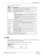
... Enter the number of the Generic Routing Encapsulation (GRE) tunnel between devices. Click this screen as shown next. Figure 45 GRE Screen WiMAX Device Configuration User's Guide 97 Set whether the WiMAX Device is Microsoft's variant of Challenge Handshake Authentication Protocol (CHAP). The Challenge Handshake Authentication Protocol (CHAP) uses... Connection Trigger Connection Timeout PPPoE Connect PPPoE Disconnect • PAP - Password Authentication Protocol uses unencrypted plaintext to send a passwords for the PPPoE interface if your ISP uses an AC PPPoE service.
... Enter the number of the Generic Routing Encapsulation (GRE) tunnel between devices. Click this screen as shown next. Figure 45 GRE Screen WiMAX Device Configuration User's Guide 97 Set whether the WiMAX Device is Microsoft's variant of Challenge Handshake Authentication Protocol (CHAP). The Challenge Handshake Authentication Protocol (CHAP) uses... Connection Trigger Connection Timeout PPPoE Connect PPPoE Disconnect • PAP - Password Authentication Protocol uses unencrypted plaintext to send a passwords for the PPPoE interface if your ISP uses an AC PPPoE service.

User Guide
Page 98
...This screen contains the following fields: Table 30 IP LABEL IP address IP Subnet Mask DESCRIPTION Enter the IP address of the LAN interface for the WiMAX Device. Figure 46 EtherIP Screen This screen contains the following fields: Table 29 EtherIP LABEL DESCRIPTION Peer IP Address ... Click Network Setting > LAN > IP to open this screen as shown next. Enter the IP subnet mask of the LAN interface for the WiMAX Device. 98 WiMAX Device Configuration User's Guide Click Network Setting > WAN > EtherIP to open this screen as shown next. Chapter 7 Network Setting This screen...
...This screen contains the following fields: Table 30 IP LABEL IP address IP Subnet Mask DESCRIPTION Enter the IP address of the LAN interface for the WiMAX Device. Figure 46 EtherIP Screen This screen contains the following fields: Table 29 EtherIP LABEL DESCRIPTION Peer IP Address ... Click Network Setting > LAN > IP to open this screen as shown next. Enter the IP subnet mask of the LAN interface for the WiMAX Device. 98 WiMAX Device Configuration User's Guide Click Network Setting > WAN > EtherIP to open this screen as shown next. Chapter 7 Network Setting This screen...

User Guide
Page 105
...Add in the Network Setting > Route > Static Route screen to configure how the WiMAX Device exchanges information with other routers. WiMAX Device Configuration User's Guide 105 Metric If the next hop is an IP address rather than an interface on the WiMAX Device, select IP Address and enter the IP... address. Select Interface and then select WAN or LAN for the next ...
...Add in the Network Setting > Route > Static Route screen to configure how the WiMAX Device exchanges information with other routers. WiMAX Device Configuration User's Guide 105 Metric If the next hop is an IP address rather than an interface on the WiMAX Device, select IP Address and enter the IP... address. Select Interface and then select WAN or LAN for the next ...

User Guide
Page 111
... times out in three minutes with UDP (User Datagram Protocol), or two hours with the "incoming" port range of trigger port forwarding. WiMAX Device Configuration User's Guide 111 Figure 59 Trigger Port Forwarding Example 1 Jane requests a file from inside the WiMAX Device and going to the outside. 2 If...7070 is a "trigger" port and causes the WiMAX Device to record Jane's computer IP address. All incoming packets received by this WiMAX Device's WAN interface will be forwarded to the DMZ host you set the IP address of your network DMZ (if you have one) for the WiMAX Device. Click...
... times out in three minutes with UDP (User Datagram Protocol), or two hours with the "incoming" port range of trigger port forwarding. WiMAX Device Configuration User's Guide 111 Figure 59 Trigger Port Forwarding Example 1 Jane requests a file from inside the WiMAX Device and going to the outside. 2 If...7070 is a "trigger" port and causes the WiMAX Device to record Jane's computer IP address. All incoming packets received by this WiMAX Device's WAN interface will be forwarded to the DMZ host you set the IP address of your network DMZ (if you have one) for the WiMAX Device. Click...

User Guide
Page 113
...This screen contains the following fields: Table 44 QoS LABEL Interface DSCP Priority OK DESCRIPTION This displays the interface for device management. Specify a DiffServ Code Point (DSCP) classification identification number (-1-63) to configure QoS settings on the application types and traffic flow. ...different markings, compared to traffic that passes through this interface. Like DSCP, this page to receive specific per-hop treatment at DiffServcompliant network devices along the route based on the WiMAX Device. Configure DiffServ Code Point (DSCP) and/or Priority marking...
...This screen contains the following fields: Table 44 QoS LABEL Interface DSCP Priority OK DESCRIPTION This displays the interface for device management. Specify a DiffServ Code Point (DSCP) classification identification number (-1-63) to configure QoS settings on the application types and traffic flow. ...different markings, compared to traffic that passes through this interface. Like DSCP, this page to receive specific per-hop treatment at DiffServcompliant network devices along the route based on the WiMAX Device. Configure DiffServ Code Point (DSCP) and/or Priority marking...

User Guide
Page 120
... is the index number of this port should not be forwarded to the specified VLANs. Port Settings # Interface Link Type PVID Note: To use VLAN on the WiMAX Device, you must configure Filter Settings for the port and VLAN ID for only one VLAN. Select Hybrid to allow packets belonging to... 4094 as shown next. Chapter 7 Network Setting Click Network Setting > VLAN to open the screen as the port VLAN ID. 120 WiMAX Device Configuration User's Guide It will remove packets forwarded out of the port setting. This will tag them with the specified PVID. The device connected to an...
... is the index number of this port should not be forwarded to the specified VLANs. Port Settings # Interface Link Type PVID Note: To use VLAN on the WiMAX Device, you must configure Filter Settings for the port and VLAN ID for only one VLAN. Select Hybrid to allow packets belonging to... 4094 as shown next. Chapter 7 Network Setting Click Network Setting > VLAN to open the screen as the port VLAN ID. 120 WiMAX Device Configuration User's Guide It will remove packets forwarded out of the port setting. This will tag them with the specified PVID. The device connected to an...


