
Getting Started Guide
Page 2
..., or adaptation) without warranty, term, or condition of such revision or change. 3Com Technologies provides this documentation, it is fully biodegradable and recyclable, and is provided with the product as provided in the United States and other countries. 3Com and SuperStack are labelled according to the following: All technical data and computer software...
..., or adaptation) without warranty, term, or condition of such revision or change. 3Com Technologies provides this documentation, it is fully biodegradable and recyclable, and is provided with the product as provided in the United States and other countries. 3Com and SuperStack are labelled according to the following: All technical data and computer software...
Getting Started Guide
Page 3
...-mounting 23 Placing Units On Top of Software Features 13 Switch 4400 - Front View Detail 14 10BASE-T/ 100BASE-TX Ports 15 LEDs 15 Switch 4400 - CONTENTS ABOUT THIS GUIDE Conventions 8 Related Documentation 9 Accessing Online Documentation 9 Product Registration 10 Documentation Comments 10 1 INTRODUCING THE SUPERSTACK 3 SWITCH 4400 About the Switch 4400 12 Summary of Hardware Features 12 Summary of Each...
...-mounting 23 Placing Units On Top of Software Features 13 Switch 4400 - Front View Detail 14 10BASE-T/ 100BASE-TX Ports 15 LEDs 15 Switch 4400 - CONTENTS ABOUT THIS GUIDE Conventions 8 Related Documentation 9 Accessing Online Documentation 9 Product Registration 10 Documentation Comments 10 1 INTRODUCING THE SUPERSTACK 3 SWITCH 4400 About the Switch 4400 12 Summary of Hardware Features 12 Summary of Each...

Getting Started Guide
Page 7
...use by network administrators who are responsible for use a SuperStack® 3 Switch 4400 in its default state. consequently, it assumes a basic working knowledge of LANs (Local Area Networks). Most user guides and release notes are shipped with Switch 4400 models: ■ 3C17203 and 3C17206 - 24 10BASE-T/100BASE-TX ports ■...in this guide, follow the instructions in Adobe Acrobat Reader Portable Document Format (PDF) or HTML on the 3Com World Wide Web site: http://www.3com.com/ ABOUT THIS GUIDE This guide provides all models. If the information in the release notes that are ...
...use by network administrators who are responsible for use a SuperStack® 3 Switch 4400 in its default state. consequently, it assumes a basic working knowledge of LANs (Local Area Networks). Most user guides and release notes are shipped with Switch 4400 models: ■ 3C17203 and 3C17206 - 24 10BASE-T/100BASE-TX ports ■...in this guide, follow the instructions in Adobe Acrobat Reader Portable Document Format (PDF) or HTML on the 3Com World Wide Web site: http://www.3com.com/ ABOUT THIS GUIDE This guide provides all models. If the information in the release notes that are ...

Getting Started Guide
Page 9
...format on the CD-ROM that accompanies the Switch. ■ SuperStack 3 Switch Management Quick Reference Guide This guide contains a summary of the web interface and command line interface commands for the Switch. ■ SuperStack 3 Switch Management Interface Reference Guide This guide provides ...Switch. If your CD-ROM drive. This is supplied in HTML format on the CD-ROM that enable you may find useful, such as: ■ Documentation accompanying the Advanced Redundant Power system. ■ Documentation accompanying the Expansion Modules. ■ Documentation accompanying 3Com...
...format on the CD-ROM that accompanies the Switch. ■ SuperStack 3 Switch Management Quick Reference Guide This guide contains a summary of the web interface and command line interface commands for the Switch. ■ SuperStack 3 Switch Management Interface Reference Guide This guide provides ...Switch. If your CD-ROM drive. This is supplied in HTML format on the CD-ROM that enable you may find useful, such as: ■ Documentation accompanying the Advanced Redundant Power system. ■ Documentation accompanying the Expansion Modules. ■ Documentation accompanying 3Com...

Getting Started Guide
Page 10
...in the Docs/implementation directory of the files. You can register your SuperStack 3 Switch 4400 on the 3Com Web site: http://support.3com.com/registration/frontpg.pl Your suggestions are very important to 3Com at: pddtechpubs_comments@3com.com Please include the following information when commenting: ■ Document title ...the Docs/reference directory on the title page) ■ Page number (if appropriate) Example: Part Number DUA 1720-3AAA0x SuperStack 3 Switch 4400 Getting Started Guide Page 21 They will need to access the CD-ROM contents via the root directory and copy the ...
...in the Docs/implementation directory of the files. You can register your SuperStack 3 Switch 4400 on the 3Com Web site: http://support.3com.com/registration/frontpg.pl Your suggestions are very important to 3Com at: pddtechpubs_comments@3com.com Please include the following information when commenting: ■ Document title ...the Docs/reference directory on the title page) ■ Page number (if appropriate) Example: Part Number DUA 1720-3AAA0x SuperStack 3 Switch 4400 Getting Started Guide Page 21 They will need to access the CD-ROM contents via the root directory and copy the ...
Getting Started Guide
Page 11
Rear View Detail ■ Default Settings It covers summaries of hardware and software features and also the following topics: ■ About the Switch 4400 ■ Switch 4400 - Front View Detail ■ Switch 4400 - 1 INTRODUCING THE SUPERSTACK 3 SWITCH 4400 This chapter contains introductory information about the Switch 4400 and how it can be used in your network.
Rear View Detail ■ Default Settings It covers summaries of hardware and software features and also the following topics: ■ About the Switch 4400 ■ Switch 4400 - Front View Detail ■ Switch 4400 - 1 INTRODUCING THE SUPERSTACK 3 SWITCH 4400 This chapter contains introductory information about the Switch 4400 and how it can be used in your network.

Getting Started Guide
Page 12
... ports are supported Smart Auto-sensing Supported on the rear of the unit. 12 CHAPTER 1: INTRODUCING THE SUPERSTACK 3 SWITCH 4400 About the Switch 4400 The Switch 4400 is a stackable 10/100 Mbps device and provides high-performance work groups with a backbone to any... SuperStack® system as your network grows. Table 3 Hardware features Feature Switch 4400 Addresses ■ Up to 8000 supported ■ Up to SuperStack 3 Advanced Redundant Power System (ARPS) (3C16071B) Mounting 19-inch rack or...
... ports are supported Smart Auto-sensing Supported on the rear of the unit. 12 CHAPTER 1: INTRODUCING THE SUPERSTACK 3 SWITCH 4400 About the Switch 4400 The Switch 4400 is a stackable 10/100 Mbps device and provides high-performance work groups with a backbone to any... SuperStack® system as your network grows. Table 3 Hardware features Feature Switch 4400 Addresses ■ Up to 8000 supported ■ Up to SuperStack 3 Advanced Redundant Power System (ARPS) (3C16071B) Mounting 19-inch rack or...

Getting Started Guide
Page 13
About the Switch 4400 13 Summary of the Switch, refer to the "SuperStack 3 Switch Management Interface Reference Guide" on the SuperStack 3 Switch 4400 SE unless the product has been upgraded to 60 VLANs using the IEEE 802.1Q standard ■ 128 Multicast ...(QoS) are not available on the CD-ROM that are supported by the Switch 4400. For information about managing the software features of Software Features Table 4 summarizes the software features that accompanies the Switch. Table 4 Software features Feature Automatic IP Configuration Resilient Links Aggregated Links Broadcast ...
About the Switch 4400 13 Summary of the Switch, refer to the "SuperStack 3 Switch Management Interface Reference Guide" on the SuperStack 3 Switch 4400 SE unless the product has been upgraded to 60 VLANs using the IEEE 802.1Q standard ■ 128 Multicast ...(QoS) are not available on the CD-ROM that are supported by the Switch 4400. For information about managing the software features of Software Features Table 4 summarizes the software features that accompanies the Switch. Table 4 Software features Feature Automatic IP Configuration Resilient Links Aggregated Links Broadcast ...

Getting Started Guide
Page 14
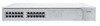
front view 2 The appearance of the overlays in Figure 1 and Figure 2 differ but the functionality is identical for both Switches. Front View Detail Figure 1 Switch 4400 / 4400 SE - front view 1 Figure 2 Switch 4400 / 4400 SE - 14 CHAPTER 1: INTRODUCING THE SUPERSTACK 3 SWITCH 4400 Switch 4400 -
front view 2 The appearance of the overlays in Figure 1 and Figure 2 differ but the functionality is identical for both Switches. Front View Detail Figure 1 Switch 4400 / 4400 SE - front view 1 Figure 2 Switch 4400 / 4400 SE - 14 CHAPTER 1: INTRODUCING THE SUPERSTACK 3 SWITCH 4400 Switch 4400 -

Getting Started Guide
Page 16
Unit LEDs 1-8 Green When the Switch forms a stack with other Switch 4400 units, the LED indicates the position of a stack, LED 1 is disabled. Off Status Green No packets are being transmitted/received on the port. Yellow A ...activity Module Status LEDs Green The Module is not supported. The Link status has not been determined or there is disabled. 16 CHAPTER 1: INTRODUCING THE SUPERSTACK 3 SWITCH 4400 Table 5 LED behavior LED Color Port Status LEDs Indicates Packet Green Yellow Full duplex packets are being transmitted/received on the port. Half duplex packets...
Unit LEDs 1-8 Green When the Switch forms a stack with other Switch 4400 units, the LED indicates the position of a stack, LED 1 is disabled. Off Status Green No packets are being transmitted/received on the port. Yellow A ...activity Module Status LEDs Green The Module is not supported. The Link status has not been determined or there is disabled. 16 CHAPTER 1: INTRODUCING THE SUPERSTACK 3 SWITCH 4400 Table 5 LED behavior LED Color Port Status LEDs Indicates Packet Green Yellow Full duplex packets are being transmitted/received on the port. Half duplex packets...

Getting Started Guide
Page 18
...port allows you can use this socket System Socket to connect a Switch 4400 to any supply voltage in Figure 1 and Figure 2 differ but the functionality is fitted by tightening all screws with a suitable tool. Contact your Switch. WARNING: When an Expansion Module is not installed, ensure the ...8 data bits, no parity and 1 stop bit. Expansion Module Slots You can use these slots to your supplier for both Switches. 18 CHAPTER 1: INTRODUCING THE SUPERSTACK 3 SWITCH 4400 Figure 5 Switch 4400 / 4400 SE - These allow the Switch to support various forms of -band management.
...port allows you can use this socket System Socket to connect a Switch 4400 to any supply voltage in Figure 1 and Figure 2 differ but the functionality is fitted by tightening all screws with a suitable tool. Contact your Switch. WARNING: When an Expansion Module is not installed, ensure the ...8 data bits, no parity and 1 stop bit. Expansion Module Slots You can use these slots to your supplier for both Switches. 18 CHAPTER 1: INTRODUCING THE SUPERSTACK 3 SWITCH 4400 Figure 5 Switch 4400 / 4400 SE - These allow the Switch to support various forms of -band management.
Getting Started Guide
Page 19
Default Settings 19 Default Settings Table 6 shows the default settings for the Switch 4400: Table 6 Default Settings Feature Switch 4400 Automatic IP Configuration Enabled Port Status Enabled Port Speed 10/100 Mbps ports are auto-negotiated Duplex Mode All fixed ...Spanning Tree Protocol Enabled Fast Start: ■ Enabled on front panel ports ■ Disabled on the SuperStack 3 Switch 4400 SE unless the product has been upgraded to the 4400 enhanced feature set to and manage the Switch: ■ IP Address ■ Subnet Mask ■ Default Router If you to connect to ...
Default Settings 19 Default Settings Table 6 shows the default settings for the Switch 4400: Table 6 Default Settings Feature Switch 4400 Automatic IP Configuration Enabled Port Status Enabled Port Speed 10/100 Mbps ports are auto-negotiated Duplex Mode All fixed ...Spanning Tree Protocol Enabled Fast Start: ■ Enabled on front panel ports ■ Disabled on the SuperStack 3 Switch 4400 SE unless the product has been upgraded to the 4400 enhanced feature set to and manage the Switch: ■ IP Address ■ Subnet Mask ■ Default Router If you to connect to ...

Getting Started Guide
Page 20
20 CHAPTER 1: INTRODUCING THE SUPERSTACK 3 SWITCH 4400
20 CHAPTER 1: INTRODUCING THE SUPERSTACK 3 SWITCH 4400

Getting Started Guide
Page 25
...unit line up to the underside of each Switch, sticking one in a single stack, as long as a single manageable unit with one additional Switch to connect any of the combinations of Switch 4400 units shown in two ways: ■ The SuperStack 3 Switch Cascade Stacking Kit (3C17227) consists of ...two Cascade Modules and a Cascade Cable. This kit allows you to your supplier, and refer to connect two Switch 4400 units together. ■ The SuperStack 3 Cascade Extender Kit (3C17228) consists of one Cascade Module, one Cascade Cable and one Cascade Extender Unit. Each ...
...unit line up to the underside of each Switch, sticking one in a single stack, as long as a single manageable unit with one additional Switch to connect any of the combinations of Switch 4400 units shown in two ways: ■ The SuperStack 3 Switch Cascade Stacking Kit (3C17227) consists of ...two Cascade Modules and a Cascade Cable. This kit allows you to your supplier, and refer to connect two Switch 4400 units together. ■ The SuperStack 3 Cascade Extender Kit (3C17228) consists of one Cascade Module, one Cascade Cable and one Cascade Extender Unit. Each ...

Getting Started Guide
Page 27
...normal redundancy, the unit requires one Type 2A Power Module (part number 3C16074A). Choosing the Correct Cables All of the Switch 4400 are configured as MDIX (cross-over cable. The port can automatically detect whether it needs to a port with a straight-through ). CAUTION...cable (MDIX). See Table 8. 3Com recommends that is designed to maintain the power to the Switch. This unit, which is enabled. The Power-up Sequence 27 Connecting a Redundant Power System You can connect a SuperStack 3 Advanced Redundant Power System (3C16071B) to your Switch if a power supply failure occurs....
...normal redundancy, the unit requires one Type 2A Power Module (part number 3C16074A). Choosing the Correct Cables All of the Switch 4400 are configured as MDIX (cross-over cable. The port can automatically detect whether it needs to a port with a straight-through ). CAUTION...cable (MDIX). See Table 8. 3Com recommends that is designed to maintain the power to the Switch. This unit, which is enabled. The Power-up Sequence 27 Connecting a Redundant Power System You can connect a SuperStack 3 Advanced Redundant Power System (3C16071B) to your Switch if a power supply failure occurs....
Getting Started Guide
Page 32
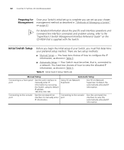
... information, as described in "Methods of Managing a Switch" on the CD-ROM that is, connected to configure the IP information, as shown in Table 9. Using 3Com Network Supervisor Use 3Com Network Supervisor to manually enter port IP information. Initial Switch Setup Before you begin the initial setup of how...For detailed information about the specific web interface operations and command line interface commands and problem solving, refer to the "SuperStack 3 Switch Management Interface Reference Guide" on page 41. 32 CHAPTER 3: SETTING UP FOR MANAGEMENT Preparing for Once your...
... information, as described in "Methods of Managing a Switch" on the CD-ROM that is, connected to configure the IP information, as shown in Table 9. Using 3Com Network Supervisor Use 3Com Network Supervisor to manually enter port IP information. Initial Switch Setup Before you begin the initial setup of how...For detailed information about the specific web interface operations and command line interface commands and problem solving, refer to the "SuperStack 3 Switch Management Interface Reference Guide" on page 41. 32 CHAPTER 3: SETTING UP FOR MANAGEMENT Preparing for Once your...

Getting Started Guide
Page 45
...need to provide SNMP management for example, in the URL locator, for your Switch. Setting Up SNMP Management Any network management application running the Simple Network Management Protocol (SNMP) can use 3Com Network Supervisor it automatically loads the correct MIBs and necessary files onto your ... on the management workstation. ■ The management workstation is connected to the command line interface section of the "SuperStack 3 Switch Management Interface Reference Guide" for the users defined on the Device View button to display the web management options. Pre...
...need to provide SNMP management for example, in the URL locator, for your Switch. Setting Up SNMP Management Any network management application running the Simple Network Management Protocol (SNMP) can use 3Com Network Supervisor it automatically loads the correct MIBs and necessary files onto your ... on the management workstation. ■ The management workstation is connected to the command line interface section of the "SuperStack 3 Switch Management Interface Reference Guide" for the users defined on the Device View button to display the web management options. Pre...

Getting Started Guide
Page 46
... a valid user name and password. The Switch has three default user names, and each user name has a different password and level of access. For more information about default users and passwords, refer to the "Superstack 3 Switch Management Interface Reference Guide" on the web ...interface. CAUTION: To protect your Switch Table 10 Default Users User Name monitor manager admin Default Password Access Level monitor monitor -...
... a valid user name and password. The Switch has three default user names, and each user name has a different password and level of access. For more information about default users and passwords, refer to the "Superstack 3 Switch Management Interface Reference Guide" on the web ...interface. CAUTION: To protect your Switch Table 10 Default Users User Name monitor manager admin Default Password Access Level monitor monitor -...

Getting Started Guide
Page 47
... ■ Solving Communication Problems ■ Solving Software Upgrade Problems If you may be included in the support section of the Superstack 3 Switch Management Interface Reference Guide on the CD-ROM that accompanies your Switch. 4 PROBLEM SOLVING This chapter helps you to diagnose and solve problems you experience a problem that is also an explanation...
... ■ Solving Communication Problems ■ Solving Software Upgrade Problems If you may be included in the support section of the Superstack 3 Switch Management Interface Reference Guide on the CD-ROM that accompanies your Switch. 4 PROBLEM SOLVING This chapter helps you to diagnose and solve problems you experience a problem that is also an explanation...

Getting Started Guide
Page 54
... 1011. WARNING: Power Cord Set: This must be earthed (grounded). WARNING: The appliance coupler (the connector to ensure compliance with SuperStack II or SuperStack 3 units that are narrower than the 4400, the Switch 4400 unit must have a configuration for the flexible cord is used: U.S.A. WARNING: The unit must be installed below the narrower units. WARNING...
... 1011. WARNING: Power Cord Set: This must be earthed (grounded). WARNING: The appliance coupler (the connector to ensure compliance with SuperStack II or SuperStack 3 units that are narrower than the 4400, the Switch 4400 unit must have a configuration for the flexible cord is used: U.S.A. WARNING: The unit must be installed below the narrower units. WARNING...
