Installation Guide
Page 3
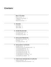
... THIS GUIDE Before You Start 5 Organization of the Manual 5 Conventions 5 Related Documentation 6 1 OVERVIEW Introduction 7 Types of SICs 9 Types of MIMs 9 2 SYSTEM SPECIFICATIONS 3Com Router Router 5012 11 3Com Router 5232 13 3Com Router Router 5682 15 3 INSTALLATION PREPARATION Requirements on Environment 17 Precautions 19 Tools, Meter and Devices 20 4 INSTALLATION OF THE ROUTER Installation...
... THIS GUIDE Before You Start 5 Organization of the Manual 5 Conventions 5 Related Documentation 6 1 OVERVIEW Introduction 7 Types of SICs 9 Types of MIMs 9 2 SYSTEM SPECIFICATIONS 3Com Router Router 5012 11 3Com Router 5232 13 3Com Router Router 5682 15 3 INSTALLATION PREPARATION Requirements on Environment 17 Precautions 19 Tools, Meter and Devices 20 4 INSTALLATION OF THE ROUTER Installation...

Installation Guide
Page 13
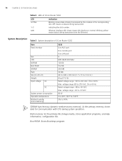
... with CPU during system operation. Boot ROM: Stores Bootstrap program. 3Com Router 5232 Appearance Figure 3 Front view of 3Com Router 5232 1) POWER 3) AUX 5) SLOT1~3 (READY/ACTIVE) Figure 4 Rear view of 3Com Router 5232 LED POWER SYSTEM READY Indication System power LED: OFF means power ... means the module runs abnormally or no module is abnormal. Module status LED: ON means the module in the following table: Table 4 LEDs of 3Com Router 5232 2) SYSTEM 4) CON 6) LAN (READY/ACTIVE) 1) Power switch 3) Grounding screw 5) Fixed WAN interface (WAN0) 7) MIM SLOT2 2) Power socket...
... with CPU during system operation. Boot ROM: Stores Bootstrap program. 3Com Router 5232 Appearance Figure 3 Front view of 3Com Router 5232 1) POWER 3) AUX 5) SLOT1~3 (READY/ACTIVE) Figure 4 Rear view of 3Com Router 5232 LED POWER SYSTEM READY Indication System power LED: OFF means power ... means the module runs abnormally or no module is abnormal. Module status LED: ON means the module in the following table: Table 4 LEDs of 3Com Router 5232 2) SYSTEM 4) CON 6) LAN (READY/ACTIVE) 1) Power switch 3) Grounding screw 5) Fixed WAN interface (WAN0) 7) MIM SLOT2 2) Power socket...
Installation Guide
Page 14
... primary memory, stores data for communication with CPU during system operation. Indicating the slot number. System Description Table 5 System description of 3Com Router 5232 LED ACTIVE 1-3 LAN Indication Blinking means data is being transceived by the module in .) 8 kg (17.6 lb) Rated voltage ... to 104°F) 5% to -60 VDC Max. OFF means no data is being transceived. 14 CHAPTER 2: SYSTEM SPECIFICATIONS Table 4 LEDs of 3Com Router 5232 Item Fixed interface Slot CPU NVRAM Boot ROM SDRAM Flash Size (H x W x D) Weight Input voltage AC DC System power consumption Operation temperature...
... primary memory, stores data for communication with CPU during system operation. Indicating the slot number. System Description Table 5 System description of 3Com Router 5232 LED ACTIVE 1-3 LAN Indication Blinking means data is being transceived by the module in .) 8 kg (17.6 lb) Rated voltage ... to 104°F) 5% to -60 VDC Max. OFF means no data is being transceived. 14 CHAPTER 2: SYSTEM SPECIFICATIONS Table 4 LEDs of 3Com Router 5232 Item Fixed interface Slot CPU NVRAM Boot ROM SDRAM Flash Size (H x W x D) Weight Input voltage AC DC System power consumption Operation temperature...
Installation Guide
Page 60
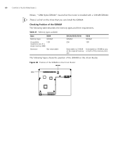
... available Item 5009 Memory type SDRAM Acceptable 128 maximum size of a single memory (MB) Extension Not extendable 5012A/5013/5014 SDRAM 256 5232 SDRAM 128 Extendable to 256MB Extendable to 256MB at any at the original memory or both of the memory slots slot The following table describes... the memory types and their requirements. Figure 42 Position of the SDRAM on the 3Com Router 60 CHAPTER 6: ROUTER MAINTENANCE Where, "128M bytes SDRAM" means that the router is a limit on the times that you can install ...
... available Item 5009 Memory type SDRAM Acceptable 128 maximum size of a single memory (MB) Extension Not extendable 5012A/5013/5014 SDRAM 256 5232 SDRAM 128 Extendable to 256MB Extendable to 256MB at any at the original memory or both of the memory slots slot The following table describes... the memory types and their requirements. Figure 42 Position of the SDRAM on the 3Com Router 60 CHAPTER 6: ROUTER MAINTENANCE Where, "128M bytes SDRAM" means that the router is a limit on the times that you can install ...
Installation Guide
Page 61
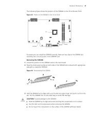
... at both sides of the SDRAM slot outward with bare hands. Hardware Maintenance 61 The following figure shows the position of the SDRAM on the 3Com 5232 To ensure you can install the SDRAM correctly, there are two clips In the SDRAM slot matching two concave points in the SDRAM card. Put.... Figure 44 Remove/install the SDRAM 3 Hold the SDRAM by its edge and avoid touching the components on the surface of the SDRAM on the 3Com Router 5232.
... at both sides of the SDRAM slot outward with bare hands. Hardware Maintenance 61 The following figure shows the position of the SDRAM on the 3Com 5232 To ensure you can install the SDRAM correctly, there are two clips In the SDRAM slot matching two concave points in the SDRAM card. Put.... Figure 44 Remove/install the SDRAM 3 Hold the SDRAM by its edge and avoid touching the components on the surface of the SDRAM on the 3Com Router 5232.
