Installation Guide
Page 3
... 5 Conventions 5 Related Documentation 6 1 OVERVIEW Introduction 7 Types of SICs 9 Types of MIMs 9 2 SYSTEM SPECIFICATIONS 3Com Router Router 5012 11 3Com Router 5232 13 3Com Router Router 5682 15 3 INSTALLATION PREPARATION Requirements on Environment 17 Precautions 19 Tools, Meter and Devices 20 4 INSTALLATION OF THE ROUTER Installation Process 21 Installing the Router to the Specified Location 22 Connecting the PGND Wire 23 Connecting the...
... 5 Conventions 5 Related Documentation 6 1 OVERVIEW Introduction 7 Types of SICs 9 Types of MIMs 9 2 SYSTEM SPECIFICATIONS 3Com Router Router 5012 11 3Com Router 5232 13 3Com Router Router 5682 15 3 INSTALLATION PREPARATION Requirements on Environment 17 Precautions 19 Tools, Meter and Devices 20 4 INSTALLATION OF THE ROUTER Installation Process 21 Installing the Router to the Specified Location 22 Connecting the PGND Wire 23 Connecting the...
Installation Guide
Page 5
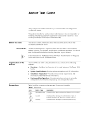
...your Router 5000. Caution Warning Information that accompany your network. consequently, it assumes a basic working knowledge of the Router 5000 Family. ■ System Specifications-Provides... system descriptions and LED information. ■ Installation Preparation-Provides environmental requirements, ESD information and tool and meter information. ■ Startup and Configuration-Provides instructions an how to set up the configuration environment, and power up network equipment; Organization of the Manual The 3Com® Router...
...your Router 5000. Caution Warning Information that accompany your network. consequently, it assumes a basic working knowledge of the Router 5000 Family. ■ System Specifications-Provides... system descriptions and LED information. ■ Installation Preparation-Provides environmental requirements, ESD information and tool and meter information. ■ Startup and Configuration-Provides instructions an how to set up the configuration environment, and power up network equipment; Organization of the Manual The 3Com® Router...

Installation Guide
Page 11
2 SYSTEM SPECIFICATIONS 3Com Router Router 5012 Appearance Figure 1 Front view of 3Com Router 5012 1) Power 3) SLOT1 5) SLOT3 7) LAN Figure 2 Rear view of 3Com Router 5012 2) SYSTEM 4) SLOT2 6) WAN 1) Power switch 3) Grounding screw 5) Console port (CON) 7) Fixed Ethernet interface (LAN) 9) SIC slot 2 2) Power socket 4) Fixed interface (WAN) 6) Auxiliary port (AUX) 8) MIM slot 1 10) SIC slot 3
2 SYSTEM SPECIFICATIONS 3Com Router Router 5012 Appearance Figure 1 Front view of 3Com Router 5012 1) Power 3) SLOT1 5) SLOT3 7) LAN Figure 2 Rear view of 3Com Router 5012 2) SYSTEM 4) SLOT2 6) WAN 1) Power switch 3) Grounding screw 5) Console port (CON) 7) Fixed Ethernet interface (LAN) 9) SIC slot 2 2) Power socket 4) Fixed interface (WAN) 6) Auxiliary port (AUX) 8) MIM slot 1 10) SIC slot 3

Installation Guide
Page 12
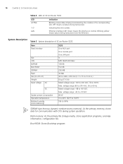
...in the following table: Table 2 LEDs of data transceiving on the fixed Ethernet interface. Fixed Ethernet interface LED: Shows the status of 3Com Router 5012 Item Slot Fixed interface CPU Boot ROM SDRAM Flash memory Size (H x W x D) Weight Input voltage AC DC System power ...44.4 x 442 x 315 mm (1.7 x 17.4 x 12.4 in the slot or the module cannot operate properly. 12 CHAPTER 2: SYSTEM SPECIFICATIONS Panel LEDs Eight LEDs are provided on . Blinking means that the interface card operates normally. System Description Table 3 System description of data transmission...
...in the following table: Table 2 LEDs of data transceiving on the fixed Ethernet interface. Fixed Ethernet interface LED: Shows the status of 3Com Router 5012 Item Slot Fixed interface CPU Boot ROM SDRAM Flash memory Size (H x W x D) Weight Input voltage AC DC System power ...44.4 x 442 x 315 mm (1.7 x 17.4 x 12.4 in the slot or the module cannot operate properly. 12 CHAPTER 2: SYSTEM SPECIFICATIONS Panel LEDs Eight LEDs are provided on . Blinking means that the interface card operates normally. System Description Table 3 System description of data transmission...
Installation Guide
Page 14
14 CHAPTER 2: SYSTEM SPECIFICATIONS Table 4 LEDs of 3Com Router 5232 Item Fixed interface Slot CPU NVRAM Boot ROM SDRAM Flash Size (H x W x D) Weight Input voltage AC DC System power consumption Operation temperature Relative humidity (noncondensing) 5232 One AUX port One console port One LAN port 3 MPC ...;C (32°F to 104°F) 5% to -60 VDC Max. Boot ROM: Stores Bootstrap program. System Description Table 5 System description of 3Com Router 5232 LED ACTIVE 1-3 LAN Indication Blinking means data is being transceived by the module in .) 8 kg (17.6 lb) Rated voltage range: 100 ...
14 CHAPTER 2: SYSTEM SPECIFICATIONS Table 4 LEDs of 3Com Router 5232 Item Fixed interface Slot CPU NVRAM Boot ROM SDRAM Flash Size (H x W x D) Weight Input voltage AC DC System power consumption Operation temperature Relative humidity (noncondensing) 5232 One AUX port One console port One LAN port 3 MPC ...;C (32°F to 104°F) 5% to -60 VDC Max. Boot ROM: Stores Bootstrap program. System Description Table 5 System description of 3Com Router 5232 LED ACTIVE 1-3 LAN Indication Blinking means data is being transceived by the module in .) 8 kg (17.6 lb) Rated voltage range: 100 ...

Installation Guide
Page 16
... 14 kg (31 lb) Rated voltage range: 100 to 240 VAC, 50 or 60 Hz Max. System Description Table 7 System description of 3Com Router 5682 LED POWER SYSTEM READY ACTIVE 0-7 Indication System power LED: OFF means power is off means system is abnormal. The corresponding slot number. ...Rated voltage range: -48 to 90% 16 CHAPTER 2: SYSTEM SPECIFICATIONS Panel LEDs 18 LEDs are provided on /off . Hardware status LED: Blinking means system is OFF when both power supplies fail. As for the router with RPS (3Com Router 5682), POWER lights when RPS works normally, POWER blinks when ...
... 14 kg (31 lb) Rated voltage range: 100 to 240 VAC, 50 or 60 Hz Max. System Description Table 7 System description of 3Com Router 5682 LED POWER SYSTEM READY ACTIVE 0-7 Indication System power LED: OFF means power is off means system is abnormal. The corresponding slot number. ...Rated voltage range: -48 to 90% 16 CHAPTER 2: SYSTEM SPECIFICATIONS Panel LEDs 18 LEDs are provided on /off . Hardware status LED: Blinking means system is OFF when both power supplies fail. As for the router with RPS (3Com Router 5682), POWER lights when RPS works normally, POWER blinks when ...

Installation Guide
Page 18
...accelerate the metal erosion and aging process of salt, acid and sulfide. 18 CHAPTER 3: INSTALLATION PREPARATION Besides the dust specifications, the equipment room of the Router should also meet the rigorous requirements for the content of some parts. Thus, the following should be considered: &#... the circuit board, and avoid contacting the devices on Although many anti-static considerations have been given to 3Com 5000 Routers, Electrostatic damage to the router's circuit or even the whole equipment may still happen when the Discharge Prevention static electricity exceeds the tolerance ...
...accelerate the metal erosion and aging process of salt, acid and sulfide. 18 CHAPTER 3: INSTALLATION PREPARATION Besides the dust specifications, the equipment room of the Router should also meet the rigorous requirements for the content of some parts. Thus, the following should be considered: &#... the circuit board, and avoid contacting the devices on Although many anti-static considerations have been given to 3Com 5000 Routers, Electrostatic damage to the router's circuit or even the whole equipment may still happen when the Discharge Prevention static electricity exceeds the tolerance ...

Installation Guide
Page 22
...the mounting ears with the recess screws to fix the router in a Rack rack. The specifications of recess screws should be installed on the router. 22 CHAPTER 4: INSTALLATION OF THE ROUTER Installing the Router to the Specified Location Install the router after you may not own a 19-inch standard ...rack. Figure 8 Installing the router in a rack tray. Use the screws to install the router: 1 Check the grounding and stability of the router will be anti-rust. Installing the Router 3Com 5000 Routers are very simple, but still, you should satisfy the ...
...the mounting ears with the recess screws to fix the router in a Rack rack. The specifications of recess screws should be installed on the router. 22 CHAPTER 4: INSTALLATION OF THE ROUTER Installing the Router to the Specified Location Install the router after you may not own a 19-inch standard ...rack. Figure 8 Installing the router in a rack tray. Use the screws to install the router: 1 Check the grounding and stability of the router will be anti-rust. Installing the Router 3Com 5000 Routers are very simple, but still, you should satisfy the ...

Installation Guide
Page 47
... is available. Press and the screen will display: This prompt indicates that the router has entered the system view, and now the router can be made specific, which include networking purpose, the role of the router in the network, the division of subnets, WAN type and transmission medium, the... network security policy and reliability. 2 Based on the router according to the WAN type. 4 ...
... is available. Press and the screen will display: This prompt indicates that the router has entered the system view, and now the router can be made specific, which include networking purpose, the role of the router in the network, the division of subnets, WAN type and transmission medium, the... network security policy and reliability. 2 Based on the router according to the WAN type. 4 ...
