
Installation Guide
Page 3
... the 3ware RAID Controller 1 Product Features 1 What's New With the 3ware 9000 Series Controllers 2 System Requirements 2 Package Contents 4 Installation Overview 5 Installing the Hardware 7 Before You Begin 8 Installation Considerations 8 What You Need: Tools and Equipment 10 Safety Factors 10 Personal Safety 10 Protecting Equipment and Data 10 Installing a Serial ATA RAID Controller 12 To connect serial cables to the controller...
... the 3ware RAID Controller 1 Product Features 1 What's New With the 3ware 9000 Series Controllers 2 System Requirements 2 Package Contents 4 Installation Overview 5 Installing the Hardware 7 Before You Begin 8 Installation Considerations 8 What You Need: Tools and Equipment 10 Safety Factors 10 Personal Safety 10 Protecting Equipment and Data 10 Installing a Serial ATA RAID Controller 12 To connect serial cables to the controller...

Installation Guide
Page 11
... flow and cooling „ Adequate power supply for serial ATA controllers. „ Operating System 3ware RAID controllers may be connected to up to the 9000 Series Datasheet, available from the website at www.3ware.com/products/serial_ata9000.asp. The length of both shielded and unshielded interface cables may not exceed 1M (39") for drives For a complete...
... flow and cooling „ Adequate power supply for serial ATA controllers. „ Operating System 3ware RAID controllers may be connected to up to the 9000 Series Datasheet, available from the website at www.3ware.com/products/serial_ata9000.asp. The length of both shielded and unshielded interface cables may not exceed 1M (39") for drives For a complete...
Installation Guide
Page 12
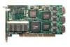
... ATA interface cables (one per port). (Cables are not included in 9500S-8MI and 9500S-12MI.) „ 3ware installation CD with the following: 3DM 2, drivers, Command Line Interface (CLI) and 3ware 9000 Series Serial ATA RAID Controller User Guide (.pdf format) „ 3ware Release Notes „ 3ware 9000 Series Serial ATA RAID Controller Installation Guide (this guide) 4 3ware 9000 Series Serial ATA RAID Controller Installation Guide
... ATA interface cables (one per port). (Cables are not included in 9500S-8MI and 9500S-12MI.) „ 3ware installation CD with the following: 3DM 2, drivers, Command Line Interface (CLI) and 3ware 9000 Series Serial ATA RAID Controller User Guide (.pdf format) „ 3ware Release Notes „ 3ware 9000 Series Serial ATA RAID Controller Installation Guide (this guide) 4 3ware 9000 Series Serial ATA RAID Controller Installation Guide

Installation Guide
Page 13
... grounded, to avoid electrostatic dis- g Close up the case. „ Power on page 99.) „ Install the controller, cables, and drives. f Connect the interface cables to the controller card. d Insert the controller card into the computer. www.3ware.com 5 Installing the Battery Backup Unit" on the system. For your reference, the list below provides an overview...
... grounded, to avoid electrostatic dis- g Close up the case. „ Power on page 99.) „ Install the controller, cables, and drives. f Connect the interface cables to the controller card. d Insert the controller card into the computer. www.3ware.com 5 Installing the Battery Backup Unit" on the system. For your reference, the list below provides an overview...

Installation Guide
Page 16
...drives you will need will depend on the slot in which to insert the controller: „ Cable routing may want to consider during installation, and the tools and equipment you will be easier if you install the 3ware RAID controller next to an open slot. It is adequate space in the chassis for... the required cables. The amount of clearance you need . Installing the Hardware Before You Begin The next few pages...
...drives you will need will depend on the slot in which to insert the controller: „ Cable routing may want to consider during installation, and the tools and equipment you will be easier if you install the 3ware RAID controller next to an open slot. It is adequate space in the chassis for... the required cables. The amount of clearance you need . Installing the Hardware Before You Begin The next few pages...

Installation Guide
Page 17
... are not already installed in the event of LED status connectors: „ Overall indicator, which lights when any drive is compatible with the 3ware RAID controller activity LEDs, such as the AMCC RDC-400 drive carrier, available through AMCC. For the location of the overall drive activity connector, see ...or drive carrier that is active. „ Individual LED indicators, for each drive. (Not supported on chassis that have a single drive activity cable that they can be easily removed in your computer, you can choose to install them either before or after connecting the interface...
... are not already installed in the event of LED status connectors: „ Overall indicator, which lights when any drive is compatible with the 3ware RAID controller activity LEDs, such as the AMCC RDC-400 drive carrier, available through AMCC. For the location of the overall drive activity connector, see ...or drive carrier that is active. „ Individual LED indicators, for each drive. (Not supported on chassis that have a single drive activity cable that they can be easily removed in your computer, you can choose to install them either before or after connecting the interface...

Installation Guide
Page 19
...inserting them upside-down. „ Interface cables are fragile and must be crimped or pinched. Do not flex the board excessively. „ Interface cable connectors must not be mated carefully with its slot on the 3ware RAID controller. Things to prevent you are keyed to... Watch Out For Be careful when installing the 3ware RAID controller into your system. Safety Factors ESD (Electrostatic Discharge...
...inserting them upside-down. „ Interface cables are fragile and must be crimped or pinched. Do not flex the board excessively. „ Interface cable connectors must not be mated carefully with its slot on the 3ware RAID controller. Things to prevent you are keyed to... Watch Out For Be careful when installing the 3ware RAID controller into your system. Safety Factors ESD (Electrostatic Discharge...
Installation Guide
Page 20
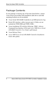
...drive status indicator: the last two pins of J9. Figure 1. 12-Port 3ware 9500S-12 Serial ATA RAID Controller Figures 2 and 3 show pchip). 12 3ware 9000 Series Serial ATA RAID Controller Installation Guide Although the controllers look very similar, the location of the overall LED drive status indicator is... located below even-numbered ports 0 through serial ATA cables. The more details, see page 13. LED indicators for drives 8, 9, 10, 11 (left to determine the Pchip version (tw_cli c0 show 3ware Serial ATA RAID controllers with twelve ports. The earlier models use Pchip v1...
...drive status indicator: the last two pins of J9. Figure 1. 12-Port 3ware 9500S-12 Serial ATA RAID Controller Figures 2 and 3 show pchip). 12 3ware 9000 Series Serial ATA RAID Controller Installation Guide Although the controllers look very similar, the location of the overall LED drive status indicator is... located below even-numbered ports 0 through serial ATA cables. The more details, see page 13. LED indicators for drives 8, 9, 10, 11 (left to determine the Pchip version (tw_cli c0 show 3ware Serial ATA RAID controllers with twelve ports. The earlier models use Pchip v1...
Installation Guide
Page 24
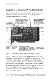
... number (on plate) SODIMM (memory module) BBU (Battery Backup Unit) connector Figure 4. 4-Port 3ware 9500S-4 Serial ATA RAID Controller To connect serial cables to the controller 1 Take out the serial cables provided with the 3ware SATA RAID controller. 3ware serial controllers are supplied with the connector on the controller. This helps to right) Overall LED drive status indicator: the last two pins of...
... number (on plate) SODIMM (memory module) BBU (Battery Backup Unit) connector Figure 4. 4-Port 3ware 9500S-4 Serial ATA RAID Controller To connect serial cables to the controller 1 Take out the serial cables provided with the 3ware SATA RAID controller. 3ware serial controllers are supplied with the connector on the controller. This helps to right) Overall LED drive status indicator: the last two pins of...

Installation Guide
Page 25
...slot. 6 Position the card in the slot so that the contacts will mate with the grooves in Which to secure the serial 3ware RAID controller after you will attach.) To install the controller in the slot, and all pins make proper contact with the grooves in the computer 1 If the computer is keyed to... at an angle. 3 Repeat steps 2 and 3 for each hard drive you have seated it down. www.3ware.com 17 Make sure that the contacts will connect one cable for each additional interface cable. (You will mate with the PCI slot pins when pushed into a full-sized PCI slot. Be careful not to...
...slot. 6 Position the card in the slot so that the contacts will mate with the grooves in Which to secure the serial 3ware RAID controller after you will attach.) To install the controller in the slot, and all pins make proper contact with the grooves in the computer 1 If the computer is keyed to... at an angle. 3 Repeat steps 2 and 3 for each hard drive you have seated it down. www.3ware.com 17 Make sure that the contacts will connect one cable for each additional interface cable. (You will mate with the PCI slot pins when pushed into a full-sized PCI slot. Be careful not to...

Installation Guide
Page 26
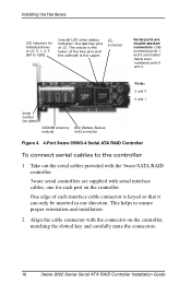
... drives 1 If your drives are connected to the power supply, either by cable or through the drive cage. 2 For each drive, select the end of each interface cable connector is keyed to the 3ware RAID Controller and plug it is desired (and supported by your hard drives), set the... appropriate jumpers on your Installation and Close the Case" on page 22. 18 3ware 9000 Series Serial ATA RAID Controller Installation Guide One edge of an interface cable not connected to ensure proper installation. 3 (Optional) Connect the drive activity LED connectors. Later, you ...
... drives 1 If your drives are connected to the power supply, either by cable or through the drive cage. 2 For each drive, select the end of each interface cable connector is keyed to the 3ware RAID Controller and plug it is desired (and supported by your hard drives), set the... appropriate jumpers on your Installation and Close the Case" on page 22. 18 3ware 9000 Series Serial ATA RAID Controller Installation Guide One edge of an interface cable not connected to ensure proper installation. 3 (Optional) Connect the drive activity LED connectors. Later, you ...
Installation Guide
Page 27
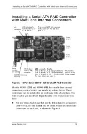
... Multi-lane Internal Connectors Installing a Serial ATA RAID Controller with a backplane. Figure 5. 12-Port 3ware 9500S-12MI Serial ATA RAID Controller Models 9500S-12MI and 9500S-8MI, have multi-lane internal connectors, each of enclosure you... need will depend on each end, as shown in an enclosure with Multi-lane Internal Connectors I2C LED indicators for drives 8, 9, 10, 11 (top to bottom) J9 are unused. www.3ware.com 19 The type of cable...
... Multi-lane Internal Connectors Installing a Serial ATA RAID Controller with a backplane. Figure 5. 12-Port 3ware 9500S-12MI Serial ATA RAID Controller Models 9500S-12MI and 9500S-8MI, have multi-lane internal connectors, each of enclosure you... need will depend on each end, as shown in an enclosure with Multi-lane Internal Connectors I2C LED indicators for drives 8, 9, 10, 11 (top to bottom) J9 are unused. www.3ware.com 19 The type of cable...

Installation Guide
Page 28
... drives you will be connecting, you are using a standard enclosure, connect each interface cable to a drive. 20 3ware 9000 Series Serial ATA RAID Controller Installation Guide See Figure 5. When the cable is inserted correctly, you will connect two or three multi-lane cables. Installing the Hardware Figure 6. If you will feel it click into place. 2 If...
... drives you will be connecting, you are using a standard enclosure, connect each interface cable to a drive. 20 3ware 9000 Series Serial ATA RAID Controller Installation Guide See Figure 5. When the cable is inserted correctly, you will connect two or three multi-lane cables. Installing the Hardware Figure 6. If you will feel it click into place. 2 If...

Installation Guide
Page 30
...cables to the controller and drives, complete the following steps to complete the hardware installation. Installing the Hardware 3 Power down the system, disconnect the drives from the 7/8000 controller and remove the controller from the system. 4 Attach the drives to "Configuring Units" on page 27 for information about configuring the RAID arrays. 22 3ware... 9000 Series Serial ATA RAID Controller Installation Guide...
...cables to the controller and drives, complete the following steps to complete the hardware installation. Installing the Hardware 3 Power down the system, disconnect the drives from the 7/8000 controller and remove the controller from the system. 4 Attach the drives to "Configuring Units" on page 27 for information about configuring the RAID arrays. 22 3ware... 9000 Series Serial ATA RAID Controller Installation Guide...
Installation Guide
Page 106
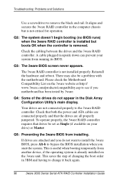
.... There may also be set as Single (if available on the 3ware unit. Check the cabling between the drives and the 3ware RAID controller. Reinstall the hardware and reboot. Check that both the power and ATA cables are all properly jumpered. It aligns and secures the 3ware RAID controller in upside down can prevent your drive) or Master. Q4...
.... There may also be set as Single (if available on the 3ware unit. Check the cabling between the drives and the 3ware RAID controller. Reinstall the hardware and reboot. Check that both the power and ATA cables are all properly jumpered. It aligns and secures the 3ware RAID controller in upside down can prevent your drive) or Master. Q4...

Installation Guide
Page 111
Figure 6. Battery cable inserted through cable management clips 5 Match the clips on the end of the BBU to the slots on the edge of the controller to create a hinge and rotate the BBU to slots on the controller Hole for post Figure 7. Clips on the controller www.3ware.com 103 Cable management clips Figure 5. BBU rotates into position on the BBU match to position it over the card, as shown in Figures 6 and 7. Installation Instructions 4 Make sure the battery cable is fastened under the cable management clips, as shown in Figure 5.
Figure 6. Battery cable inserted through cable management clips 5 Match the clips on the end of the BBU to the slots on the edge of the controller to create a hinge and rotate the BBU to slots on the controller Hole for post Figure 7. Clips on the controller www.3ware.com 103 Cable management clips Figure 5. BBU rotates into position on the BBU match to position it over the card, as shown in Figures 6 and 7. Installation Instructions 4 Make sure the battery cable is fastened under the cable management clips, as shown in Figure 5.

Installation Guide
Page 116
For detailed instructions, see the 3ware 9000 Series Serial ATA RAID Controller User Guide. 108 3ware 9000 Series Serial ATA RAID Controller Installation Guide Installing the Battery Backup Unit 3 Disconnect the battery power cable from the BBU page of either 3BM or 3DM 2. You can run the battery test from the ... estimated battery capacity of the slot. Figure 11. Power cable from the battery to the BBU 4 Slide the battery out of the plastic. 5 Insert the new battery and cable it up. 6 If necessary, reinstall the 3ware RAID controller, close up your system and restart it out of this...
For detailed instructions, see the 3ware 9000 Series Serial ATA RAID Controller User Guide. 108 3ware 9000 Series Serial ATA RAID Controller Installation Guide Installing the Battery Backup Unit 3 Disconnect the battery power cable from the BBU page of either 3BM or 3DM 2. You can run the battery test from the ... estimated battery capacity of the slot. Figure 11. Power cable from the battery to the BBU 4 Slide the battery out of the plastic. 5 Insert the new battery and cable it up. 6 If necessary, reinstall the 3ware RAID controller, close up your system and restart it out of this...
Installation Guide
Page 118
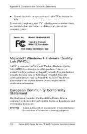
However, a product's software drivers are typically submitted for certification at www.3ware.com for current certification information. European Community Conformity Statement The StorSwitch Controller Card Model StorSwitch 4D is committed to market. Since the certification process ...limits, use shielded cables and connectors between all its products. Compliance and Conformity Statements „ Consult the dealer or an experienced radio/TV technician for all parts of information technology equipment 110 3ware 9000 Series Serial ATA RAID Controller Installation Guide Appendix ...
However, a product's software drivers are typically submitted for certification at www.3ware.com for current certification information. European Community Conformity Statement The StorSwitch Controller Card Model StorSwitch 4D is committed to market. Since the certification process ...limits, use shielded cables and connectors between all its products. Compliance and Conformity Statements „ Consult the dealer or an experienced radio/TV technician for all parts of information technology equipment 110 3ware 9000 Series Serial ATA RAID Controller Installation Guide Appendix ...
Installation Guide
Page 125
... 19 BBU (battery backup unit) installation 99 replacing the battery 99 BIOS Manager 34 C cable length, routing space, air flow 8 Compliance and Conformity 109 configuring BIOS Manager 34 determining RAID level to use 31 initializing units 49 RAID concepts and levels 28 units 40 using 3BM 38 D distributed parity 29 drive capacity 32... for Linux 66 F FreeBSD, installing driver under 87 H hardware troubleshooting 97 hot spare 29 hot spare, specifying 46 hot swap 29 I initializing units 49 installing cables 8 drive considerations 9 driver under FreeBSD 87 www.3ware.com 117
... 19 BBU (battery backup unit) installation 99 replacing the battery 99 BIOS Manager 34 C cable length, routing space, air flow 8 Compliance and Conformity 109 configuring BIOS Manager 34 determining RAID level to use 31 initializing units 49 RAID concepts and levels 28 units 40 using 3BM 38 D distributed parity 29 drive capacity 32... for Linux 66 F FreeBSD, installing driver under 87 H hardware troubleshooting 97 hot spare 29 hot spare, specifying 46 hot swap 29 I initializing units 49 installing cables 8 drive considerations 9 driver under FreeBSD 87 www.3ware.com 117

Installation Guide
Page 126
... 65 M mirrored array 28 module names for RedHat Linux 71 motherboard boot sequence 51 multilane cable, with individual SATA connectors 20 multilane cable, with multilane connectors on each end (847) 20 P PCI slots 8 R RAID concepts and levels 28 RAID level to use, determining 31 Red Hat Linux, installing driver under 68 RedHat kernel strings... 10 Troubleshooting 97 troubleshooting 97 U units configuring 27, 40 initializing 49 W Warranty 112 Windows, installing driver under 53 write cache, enabling or disabling 43 118 3ware 9000 Series Serial ATA RAID Controller Installation Guide
... 65 M mirrored array 28 module names for RedHat Linux 71 motherboard boot sequence 51 multilane cable, with individual SATA connectors 20 multilane cable, with multilane connectors on each end (847) 20 P PCI slots 8 R RAID concepts and levels 28 RAID level to use, determining 31 Red Hat Linux, installing driver under 68 RedHat kernel strings... 10 Troubleshooting 97 troubleshooting 97 U units configuring 27, 40 initializing 49 W Warranty 112 Windows, installing driver under 53 write cache, enabling or disabling 43 118 3ware 9000 Series Serial ATA RAID Controller Installation Guide