
Installation Guide
Page 13
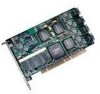
... Connect the interface cables to the drives. charge, which you are included in this guide. www.3ware.com 5 d Insert the controller card into the computer. f Connect the interface cables to the controller card. c Make sure you are working. For your reference, the list below provides an overview of... the main steps required. „ If you have a Battery Backup Unit (BBU), install it on page 99.) „ Install the controller, cables, and drives. The basic steps are not already installed in the computer, install them. b Turn off power...
... Connect the interface cables to the drives. charge, which you are included in this guide. www.3ware.com 5 d Insert the controller card into the computer. f Connect the interface cables to the controller card. c Make sure you are working. For your reference, the list below provides an overview of... the main steps required. „ If you have a Battery Backup Unit (BBU), install it on page 99.) „ Install the controller, cables, and drives. The basic steps are not already installed in the computer, install them. b Turn off power...
Installation Guide
Page 15
Be sure to read this section. „ "Installing a Serial ATA RAID Controller" and "Installing a Serial ATA RAID Controller with Multi-lane Internal Connectors" provide step-by-step instructions for your personal safety and to follow when you have a BBU (Battery Backup Unit), install it first. www.3ware.com 7 Installing the Battery Backup Unit" on page 99. Note...
Be sure to read this section. „ "Installing a Serial ATA RAID Controller" and "Installing a Serial ATA RAID Controller with Multi-lane Internal Connectors" provide step-by-step instructions for your personal safety and to follow when you have a BBU (Battery Backup Unit), install it first. www.3ware.com 7 Installing the Battery Backup Unit" on page 99. Note...
Installation Guide
Page 20
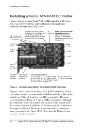
... (left to determine the Pchip version (tw_cli c0 show 3ware Serial ATA RAID controllers with twelve ports. connector stacked connectors. I2C Serial ports are BBU-compatible. J9 is the lower of J9. The earlier models use the 3ware CLI to right) J7 and J8 are unused. Ports 10...left to right) The last two pins on J8 is the upper. Figure 1. 12-Port 3ware 9500S-12 Serial ATA RAID Controller Figures 2 and 3 show pchip). 12 3ware 9000 Series Serial ATA RAID Controller Installation Guide Up to twelve drives can use Pchip v1.4 and are located below even-numbered ...
... (left to determine the Pchip version (tw_cli c0 show 3ware Serial ATA RAID controllers with twelve ports. connector stacked connectors. I2C Serial ports are BBU-compatible. J9 is the lower of J9. The earlier models use the 3ware CLI to right) J7 and J8 are unused. Ports 10...left to right) The last two pins on J8 is the upper. Figure 1. 12-Port 3ware 9500S-12 Serial ATA RAID Controller Figures 2 and 3 show pchip). 12 3ware 9000 Series Serial ATA RAID Controller Installation Guide Up to twelve drives can use Pchip v1.4 and are located below even-numbered ...
Installation Guide
Page 21
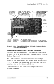
... 4-port card. The evennumbered pins are 3.3V for the anode side of each 10-pin connector. Figure 2. 8-Port 3ware 9500S-8 Serial ATA RAID Controller, Pchip v1.5 (BBU-compatible) Additional Details About the LED Status Connectors As shown in the lower left to right) J7 and J8 are unused.... Installing a Serial ATA RAID Controller LED indicators for individual drives on J8 is for drives 4, 5, 6, 7 (left -hand corner of ...
... 4-port card. The evennumbered pins are 3.3V for the anode side of each 10-pin connector. Figure 2. 8-Port 3ware 9500S-8 Serial ATA RAID Controller, Pchip v1.5 (BBU-compatible) Additional Details About the LED Status Connectors As shown in the lower left to right) J7 and J8 are unused.... Installing a Serial ATA RAID Controller LED indicators for individual drives on J8 is for drives 4, 5, 6, 7 (left -hand corner of ...
Installation Guide
Page 23
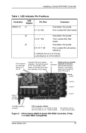
... upper. I2C Serial ports are located below even-numbered ports 0 through 6. The anode is the lower of J9. Installing a Serial ATA RAID Controller Table 1: LED Indicator Pin Positions Controller LED Header Pin Pair 9500S-12 J7 : : : : : 0 1 2 3 NU Comment Orientation Horizontal Port number/NU (Not Used) J8 : : : : : Orientation Horizontal 4 ... 4, 5, 6, 7 (left to right) J8 is for individual drives on J7 and J8 are unused. Figure 3. 8-Port 3ware 9500S-8 Serial ATA RAID Controller, Pchip v1.4 (Non-BBU Compatible) www.3ware.com 15 connector stacked connectors.
... upper. I2C Serial ports are located below even-numbered ports 0 through 6. The anode is the lower of J9. Installing a Serial ATA RAID Controller Table 1: LED Indicator Pin Positions Controller LED Header Pin Pair 9500S-12 J7 : : : : : 0 1 2 3 NU Comment Orientation Horizontal Port number/NU (Not Used) J8 : : : : : Orientation Horizontal 4 ... 4, 5, 6, 7 (left to right) J8 is for individual drives on J7 and J8 are unused. Figure 3. 8-Port 3ware 9500S-8 Serial ATA RAID Controller, Pchip v1.4 (Non-BBU Compatible) www.3ware.com 15 connector stacked connectors.
Installation Guide
Page 24
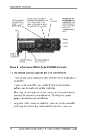
... connector Serial ports are located below evennumbered ports 0 and 2. Ports: 2 and 3 0 and 1 Serial number (on plate) SODIMM (memory module) BBU (Battery Backup Unit) connector Figure 4. 4-Port 3ware 9500S-4 Serial ATA RAID Controller To connect serial cables to ensure proper orientation and installation 2 Align the cable connector with serial interface cables, one direction. Installing the Hardware...
... connector Serial ports are located below evennumbered ports 0 and 2. Ports: 2 and 3 0 and 1 Serial number (on plate) SODIMM (memory module) BBU (Battery Backup Unit) connector Figure 4. 4-Port 3ware 9500S-4 Serial ATA RAID Controller To connect serial cables to ensure proper orientation and installation 2 Align the cable connector with serial interface cables, one direction. Installing the Hardware...
Installation Guide
Page 27
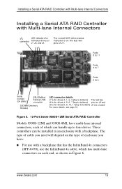
For more details, see page 16. Figure 5. 12-Port 3ware 9500S-12MI Serial ATA RAID Controller Models 9500S-12MI and 9500S-8MI, have : „ For use the InfiniBand 4x cable, which can be installed in Figure 6. www.3ware.com 19 The type of cable you need will depend on J8 and J9 is ... Installing a Serial ATA RAID Controller with Multi-lane Internal Connectors I2C LED indicators for connector individual drives on each of which has multi-lane connectors on J7, J8, and J9. Ports 8 to 11 Ports 4 to 7 Ports 0 to 3 Serial number (on plate) BBU (Battery Backup Unit) ...
For more details, see page 16. Figure 5. 12-Port 3ware 9500S-12MI Serial ATA RAID Controller Models 9500S-12MI and 9500S-8MI, have : „ For use the InfiniBand 4x cable, which can be installed in Figure 6. www.3ware.com 19 The type of cable you need will depend on J8 and J9 is ... Installing a Serial ATA RAID Controller with Multi-lane Internal Connectors I2C LED indicators for connector individual drives on each of which has multi-lane connectors on J7, J8, and J9. Ports 8 to 11 Ports 4 to 7 Ports 0 to 3 Serial number (on plate) BBU (Battery Backup Unit) ...

Installation Guide
Page 46
... to the left of the primary buttons on the main screen: Create Delete Maintain Rebuild Policy BBU Enter Up and Down Arrow Keys Alt+A Alt+C Alt+D Alt+M Alt+R Alt+P Alt+B 38 3ware 9000 Series Serial ATA RAID Controller Installation Guide Any unit that is currently Enter or the Spacebar highlighted. A selection may be listed...
... to the left of the primary buttons on the main screen: Create Delete Maintain Rebuild Policy BBU Enter Up and Down Arrow Keys Alt+A Alt+C Alt+D Alt+M Alt+R Alt+P Alt+B 38 3ware 9000 Series Serial ATA RAID Controller Installation Guide Any unit that is currently Enter or the Spacebar highlighted. A selection may be listed...

Installation Guide
Page 47
... Manager screen, from the Advanced Details screen Any key Move a highlighted unit up or down in the list of the 3ware card, and whether or not BBU-support is available.) Shift+F5 Return to the board selection screen. R (Remove) Return to starting values for this Use these keys ... is highlighted.] Display context sensitive help F1 or Alt+F1 If you exit the Policy screen. www.3ware.com 39 they can see the software versions (BIOS, Firmware, monitor), serial number, controller and model number, cache memory size, slot # of exportable units (The top-most unit will become...
... Manager screen, from the Advanced Details screen Any key Move a highlighted unit up or down in the list of the 3ware card, and whether or not BBU-support is available.) Shift+F5 Return to the board selection screen. R (Remove) Return to starting values for this Use these keys ... is highlighted.] Display context sensitive help F1 or Alt+F1 If you exit the Policy screen. www.3ware.com 39 they can see the software versions (BIOS, Firmware, monitor), serial number, controller and model number, cache memory size, slot # of exportable units (The top-most unit will become...
Installation Guide
Page 107
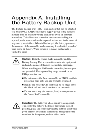
... contents of a system power failure. The cooler the battery, the longer the battery lasts. Installing the Battery Backup Unit The Battery Backup Unit (BBU) is an add-on the 3ware RAID controller. When installing the BBU on the controller, be attached to a 3ware 9000 RAID controller to supply power to data loss in the system, such as video cards.
... contents of a system power failure. The cooler the battery, the longer the battery lasts. Installing the Battery Backup Unit The Battery Backup Unit (BBU) is an add-on the 3ware RAID controller. When installing the BBU on the controller, be attached to a 3ware 9000 RAID controller to supply power to data loss in the system, such as video cards.

Installation Guide
Page 108
... „ Phillips-head screwdriver „ Grounding strap „ Battery Backup Unit (BBU) and battery „ 3ware 9000 series controller Installation Overview The Battery Backup Unit (BBU) attaches to post on the BBU (bottom view) 100 3ware 9000 Series Serial ATA RAID Controller Installation Guide Points of the controller (visible after removing the PCI bracket) match to clips on the...
... „ Phillips-head screwdriver „ Grounding strap „ Battery Backup Unit (BBU) and battery „ 3ware 9000 series controller Installation Overview The Battery Backup Unit (BBU) attaches to post on the BBU (bottom view) 100 3ware 9000 Series Serial ATA RAID Controller Installation Guide Points of the controller (visible after removing the PCI bracket) match to clips on the...

Installation Guide
Page 109
Installation Overview a) Slots on the half-height controller (top view) Note: If your 9000 series controller does not have the BBU receptacle, contact technical support for assistance. Points of connection on the full-height controller (top view) a) Slots on the edge b) BBU receptacle c) Hole for post Figure 2. www.3ware.com 101 Points of connection on the edge b) BBU receptacle c) Hole for post Figure 3.
Installation Overview a) Slots on the half-height controller (top view) Note: If your 9000 series controller does not have the BBU receptacle, contact technical support for assistance. Points of connection on the full-height controller (top view) a) Slots on the edge b) BBU receptacle c) Hole for post Figure 2. www.3ware.com 101 Points of connection on the edge b) BBU receptacle c) Hole for post Figure 3.

Installation Guide
Page 111
Battery cable inserted through cable management clips 5 Match the clips on the end of the BBU to the slots on the edge of the controller to create a hinge and rotate the BBU to slots on the controller Hole for post Figure 7. Installation Instructions 4 Make sure the battery cable is fastened under the cable management clips, as shown in Figure 5. Clips on the controller www.3ware.com 103 Figure 6. BBU rotates into position on the BBU match to position it over the card, as shown in Figures 6 and 7. Cable management clips Figure 5.
Battery cable inserted through cable management clips 5 Match the clips on the end of the BBU to the slots on the edge of the controller to create a hinge and rotate the BBU to slots on the controller Hole for post Figure 7. Installation Instructions 4 Make sure the battery cable is fastened under the cable management clips, as shown in Figure 5. Clips on the controller www.3ware.com 103 Figure 6. BBU rotates into position on the BBU match to position it over the card, as shown in Figures 6 and 7. Cable management clips Figure 5.

Installation Guide
Page 112
...PCI bracket, using the phillips screws you removed in Step 2. BBU attached to the controller with these connectors: „ Mate the connector on the BBU with the receptacle on the controller. „ Match the plastic post on the BBU with the hole on top of the board, with screws inserted... the full-height board, the bracket sits on the controller. 7 Press down gently until the BBU is seated. Appendix A. For the half-height board, the bracket sits on the bottom of the board, and screws are inserted from the top. 104 3ware 9000 Series Serial ATA RAID Controller Installation Guide
...PCI bracket, using the phillips screws you removed in Step 2. BBU attached to the controller with these connectors: „ Mate the connector on the BBU with the receptacle on the controller. „ Match the plastic post on the BBU with the hole on top of the board, with screws inserted... the full-height board, the bracket sits on the controller. 7 Press down gently until the BBU is seated. Appendix A. For the half-height board, the bracket sits on the bottom of the board, and screws are inserted from the top. 104 3ware 9000 Series Serial ATA RAID Controller Installation Guide

Installation Guide
Page 113
Figure 9. Battery power connector and power receptacle The controller is now ready to be replaced. For details, see 3ware 9000 Series Serial ATA RAID Controller User Guide. www.3ware.com 105 You can check the status of the battery, and run a battery test to determine if the battery needs to install in your system. Installation Instructions 9 Insert the battery power connector into the power receptacle on 3ware controllers. Figures 10 and 11 show the BBU fully installed on the BBU.
Figure 9. Battery power connector and power receptacle The controller is now ready to be replaced. For details, see 3ware 9000 Series Serial ATA RAID Controller User Guide. www.3ware.com 105 You can check the status of the battery, and run a battery test to determine if the battery needs to install in your system. Installation Instructions 9 Insert the battery power connector into the power receptacle on 3ware controllers. Figures 10 and 11 show the BBU fully installed on the BBU.

Installation Guide
Page 114
Installing the Battery Backup Unit Figure 10. Appendix A. BBU installed on controllers 106 3ware 9000 Series Serial ATA RAID Controller Installation Guide
Installing the Battery Backup Unit Figure 10. Appendix A. BBU installed on controllers 106 3ware 9000 Series Serial ATA RAID Controller Installation Guide
Installation Guide
Page 115
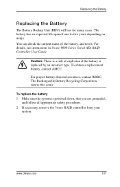
For details, see instructions in 3ware 9000 Series Serial ATA RAID Controller User Guide. To replace the battery 1 Make sure the system is replaced by an incorrect type. The battery has an expected life span of the ... (www.rbrc.com). Replacing the Battery Replacing the Battery The Battery Backup Unit (BBU) will last for many years. www.3ware.com 107 Caution: There is a risk of explosion if the battery is powered down, that you are grounded, and follow all appropriate safety procedures. 2 If necessary, remove the 3ware RAID controller from your system.
For details, see instructions in 3ware 9000 Series Serial ATA RAID Controller User Guide. To replace the battery 1 Make sure the system is replaced by an incorrect type. The battery has an expected life span of the ... (www.rbrc.com). Replacing the Battery Replacing the Battery The Battery Backup Unit (BBU) will last for many years. www.3ware.com 107 Caution: There is a risk of explosion if the battery is powered down, that you are grounded, and follow all appropriate safety procedures. 2 If necessary, remove the 3ware RAID controller from your system.

Installation Guide
Page 116
...-like clip on the battery power connector and slide it . 7 Run a battery test to the BBU 4 Slide the battery out of the plastic. 5 Insert the new battery and cable it up. 6 If necessary, reinstall the 3ware RAID controller, close up your system and restart it out of either 3BM or 3DM 2. Figure 11. Appendix...
...-like clip on the battery power connector and slide it . 7 Run a battery test to the BBU 4 Slide the battery out of the plastic. 5 Insert the new battery and cable it up. 6 If necessary, reinstall the 3ware RAID controller, close up your system and restart it out of either 3BM or 3DM 2. Figure 11. Appendix...
Installation Guide
Page 120
... with this product against defects in material and workmanship for a period of twelve (12) months from the date of purchase. 112 3ware 9000 Series Serial ATA RAID Controller Installation Guide Battery Backup Unit (BBU) Hardware. 1-Year Hardware Warranty: AMCC warrants this provision shall become the property of improper workmanship or materials. Repair parts or...
... with this product against defects in material and workmanship for a period of twelve (12) months from the date of purchase. 112 3ware 9000 Series Serial ATA RAID Controller Installation Guide Battery Backup Unit (BBU) Hardware. 1-Year Hardware Warranty: AMCC warrants this provision shall become the property of improper workmanship or materials. Repair parts or...
Installation Guide
Page 125
... in 38 A Accelerated Graphics Port (AGP) 8 auto-carving 33, 47 B backplane, using with multi-lane connectors 19 BBU (battery backup unit) installation 99 replacing the battery 99 BIOS Manager 34 C cable length, routing space, air flow 8 ...Compliance and Conformity 109 configuring BIOS Manager 34 determining RAID level to use 31 initializing units 49 RAID concepts and levels 28 units 40 using 3BM 38 D distributed parity 29 drive capacity 32 drive... I initializing units 49 installing cables 8 drive considerations 9 driver under FreeBSD 87 www.3ware.com 117
... in 38 A Accelerated Graphics Port (AGP) 8 auto-carving 33, 47 B backplane, using with multi-lane connectors 19 BBU (battery backup unit) installation 99 replacing the battery 99 BIOS Manager 34 C cable length, routing space, air flow 8 ...Compliance and Conformity 109 configuring BIOS Manager 34 determining RAID level to use 31 initializing units 49 RAID concepts and levels 28 units 40 using 3BM 38 D distributed parity 29 drive capacity 32 drive... I initializing units 49 installing cables 8 drive considerations 9 driver under FreeBSD 87 www.3ware.com 117