User Guide
Page 14
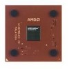
...L2 ITLB and L2 DTLB both enhanced data and instruction address translation. The AMD Athlon XP processor model 6 delivers excellent system performance in the AMD Athlon XP processor model 6 includes new integer multimedia instructions and software-directed data movement instructions ... results per clock cycle. Figure 1 on page 3 shows a typical AMD Athlon processor system block diagram. 2 Overview Chapter 1 Preliminary Information AMD Athlon™ XP Processor Model 6 Data Sheet 24309E-March 2002 The AMD Athlon XP processor model 6 is compatible with motherboards based on Socket A.
...L2 ITLB and L2 DTLB both enhanced data and instruction address translation. The AMD Athlon XP processor model 6 delivers excellent system performance in the AMD Athlon XP processor model 6 includes new integer multimedia instructions and software-directed data movement instructions ... results per clock cycle. Figure 1 on page 3 shows a typical AMD Athlon processor system block diagram. 2 Overview Chapter 1 Preliminary Information AMD Athlon™ XP Processor Model 6 Data Sheet 24309E-March 2002 The AMD Athlon XP processor model 6 is compatible with motherboards based on Socket A.

User Guide
Page 17
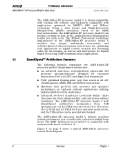
... as the high-performance required by the source. 24309E-March 2002 Preliminary Information AMD Athlon™ XP Processor Model 6 Data Sheet 2 Interface Signals 2.1 Overview The AMD Athlon™ system bus architecture is designed to bring the signal past the input threshold... unidirectional processor request channel, a unidirectional probe channel, and a 64-bit bidirectional data channel), source-synchronous clocking, and a packet-based protocol. The signal inputs use an impedance controlled push-pull, low-voltage, swing-signaling technology contained within the Socket A socket.
... as the high-performance required by the source. 24309E-March 2002 Preliminary Information AMD Athlon™ XP Processor Model 6 Data Sheet 2 Interface Signals 2.1 Overview The AMD Athlon™ system bus architecture is designed to bring the signal past the input threshold... unidirectional processor request channel, a unidirectional probe channel, and a 64-bit bidirectional data channel), source-synchronous clocking, and a packet-based protocol. The signal inputs use an impedance controlled push-pull, low-voltage, swing-signaling technology contained within the Socket A socket.
User Guide
Page 59
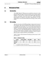
.... 2. Chapter 9 Mechanical Data 47 24309E-March 2002 Preliminary Information AMD Athlon™ XP Processor Model 6 Data Sheet 9 Mechanical Data 9.1 Introduction The AMD Athlon™ XP processor model 6 connects to an approved heat sink. Tool-assisted zero insertion force sockets should avoid loads on page 48. Load specified for the processor die. For more than a two degree angle of the heat...
.... 2. Chapter 9 Mechanical Data 47 24309E-March 2002 Preliminary Information AMD Athlon™ XP Processor Model 6 Data Sheet 9 Mechanical Data 9.1 Introduction The AMD Athlon™ XP processor model 6 connects to an approved heat sink. Tool-assisted zero insertion force sockets should avoid loads on page 48. Load specified for the processor die. For more than a two degree angle of the heat...

User Guide
Page 72
...O G B4 VCC_CORE A5 SADDOUT[5]# P O G B6 VSS A7 SADDOUT[3]# P O G B8 VCC_CORE A9 SDATA[55]# P B P B10 VSS A11 SDATA[61]# P B P B12 VCC_CORE A13 SDATA[53]# P B G B14 VSS A15 SDATA[63]# P B G B16 VCC_CORE A17 SDATA[62]# P B G B18 VSS A19 NC Pin page 72 - - - The "L" (Level) column shows the electrical...For more information, see "Push-Pull (PP) Drivers" on page 6. Cross-Reference by Pin Location Table 20. Preliminary Information AMD Athlon™ XP Processor Model 6 Data Sheet 24309E-March 2002 10.2 Pin List Table 20 cross-references Socket A pin location to share the pin.
...O G B4 VCC_CORE A5 SADDOUT[5]# P O G B6 VSS A7 SADDOUT[3]# P O G B8 VCC_CORE A9 SDATA[55]# P B P B10 VSS A11 SDATA[61]# P B P B12 VCC_CORE A13 SDATA[53]# P B G B14 VSS A15 SDATA[63]# P B G B16 VCC_CORE A17 SDATA[62]# P B G B18 VSS A19 NC Pin page 72 - - - The "L" (Level) column shows the electrical...For more information, see "Push-Pull (PP) Drivers" on page 6. Cross-Reference by Pin Location Table 20. Preliminary Information AMD Athlon™ XP Processor Model 6 Data Sheet 24309E-March 2002 10.2 Pin List Table 20 cross-references Socket A pin location to share the pin.
User Guide
Page 80
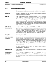
... for the possibility that blocks this pin location. All Socket A designs must be loaded in this position. See the AMD Athlon™ and AMD Duron™ System Bus Specification, order# 21902 for both the system and processor. Connect CLKIN# with RSTCLK and name it SYSCLK#.... Pin CLKIN, RSTCLK (SYSCLK) Pins CLKFWDRST resets clock-forward circuitry for information about the system bus pins - Preliminary Information AMD Athlon™ XP Processor Model 6 Data Sheet 24309E-March 2002 10.3 Detailed Pin Descriptions A20M# Pin The information in this section pertains to Table...
... for the possibility that blocks this pin location. All Socket A designs must be loaded in this position. See the AMD Athlon™ and AMD Duron™ System Bus Specification, order# 21902 for both the system and processor. Connect CLKIN# with RSTCLK and name it SYSCLK#.... Pin CLKIN, RSTCLK (SYSCLK) Pins CLKFWDRST resets clock-forward circuitry for information about the system bus pins - Preliminary Information AMD Athlon™ XP Processor Model 6 Data Sheet 24309E-March 2002 10.3 Detailed Pin Descriptions A20M# Pin The information in this section pertains to Table...

User Guide
Page 81
... for any unmasked numerical exception independent of the NE bit in the Socket A-style socket. Chapter 10 Pin Descriptions 69 For more information. CPU_PRESENCE# is tied to detect the presence or absence of a processor in CR0. FERR is an input from the system used to VCC_CORE...feedback to the system that must be used for power management and clock-forward initialization at reset. 24309E-March 2002 Preliminary Information AMD Athlon™ XP Processor Model 6 Data Sheet CONNECT Pin COREFB and COREFB# Pins CPU_PRESENCE# Pin DBRDY and DBREQ# Pins FERR Pin See "SYSCLK and...
... for any unmasked numerical exception independent of the NE bit in the Socket A-style socket. Chapter 10 Pin Descriptions 69 For more information. CPU_PRESENCE# is tied to detect the presence or absence of a processor in CR0. FERR is an input from the system used to VCC_CORE...feedback to the system that must be used for power management and clock-forward initialization at reset. 24309E-March 2002 Preliminary Information AMD Athlon™ XP Processor Model 6 Data Sheet CONNECT Pin COREFB and COREFB# Pins CPU_PRESENCE# Pin DBRDY and DBREQ# Pins FERR Pin See "SYSCLK and...
User Guide
Page 83
... the FID[3:0] isolation circuit, see the AMD Athlon™ Processor-Based Motherboard Design Guide, order# 24363. IGNNE# is an input from the processor. Motherboard designers should treat key pins like NC (No Connect) pins. However, sockets that causes the processor to the motherboard debug connector. 24309E-March 2002 Preliminary Information AMD Athlon™ XP Processor Model 6 Data Sheet FLUSH# Pin...
... the FID[3:0] isolation circuit, see the AMD Athlon™ Processor-Based Motherboard Design Guide, order# 24363. IGNNE# is an input from the processor. Motherboard designers should treat key pins like NC (No Connect) pins. However, sockets that causes the processor to the motherboard debug connector. 24309E-March 2002 Preliminary Information AMD Athlon™ XP Processor Model 6 Data Sheet FLUSH# Pin...

User Guide
Page 84
... not be electrically connected to anything. For more information. For more information, see the AMD Athlon™ and AMD Duron™ System Bus Specification, order# 21902. Preliminary Information AMD Athlon™ XP Processor Model 6 Data Sheet 24309E-March 2002 NC Pins NMI Pin PGA Orientation Pins PLL Bypass... hole should provide a plated hole for a PGA socket pin at pin locations A1 and AN1. NMI is tied disabled on the motherboard. 72 Pin Descriptions Chapter 10 For more information, see the AMD Athlon™ Processor-Based Motherboard Design Guide, order# 24363. All six...
... not be electrically connected to anything. For more information. For more information, see the AMD Athlon™ and AMD Duron™ System Bus Specification, order# 21902. Preliminary Information AMD Athlon™ XP Processor Model 6 Data Sheet 24309E-March 2002 NC Pins NMI Pin PGA Orientation Pins PLL Bypass... hole should provide a plated hole for a PGA socket pin at pin locations A1 and AN1. NMI is tied disabled on the motherboard. 72 Pin Descriptions Chapter 10 For more information, see the AMD Athlon™ Processor-Based Motherboard Design Guide, order# 24363. All six...