
User Guide
Page 3
24309E-March 2002 Preliminary Information AMD Athlon™ XP Processor Model 6 Data Sheet Contents Revision History xi 1 Overview 1 1.1 QuantiSpeed™ Architecture Summary 2 2 Interface Signals 5 2.1 Overview 5 2.2 Signaling Technology 5 2.3 Push-Pull (PP) Drivers 6 2.4 AMD Athlon™ System Bus Signals 6 3 Logic Symbol Diagram 7 4 Power ... 7.8 Absolute Ratings 30 7.9 VCC_CORE Voltage and Current 31 7.10 SYSCLK and SYSCLK# AC and DC Characteristics 32 7.11 AMD Athlon System Bus AC and DC Characteristics . . . . . 34 7.12 General AC and DC Characteristics 36 7.13 Open...
24309E-March 2002 Preliminary Information AMD Athlon™ XP Processor Model 6 Data Sheet Contents Revision History xi 1 Overview 1 1.1 QuantiSpeed™ Architecture Summary 2 2 Interface Signals 5 2.1 Overview 5 2.2 Signaling Technology 5 2.3 Push-Pull (PP) Drivers 6 2.4 AMD Athlon™ System Bus Signals 6 3 Logic Symbol Diagram 7 4 Power ... 7.8 Absolute Ratings 30 7.9 VCC_CORE Voltage and Current 31 7.10 SYSCLK and SYSCLK# AC and DC Characteristics 32 7.11 AMD Athlon System Bus AC and DC Characteristics . . . . . 34 7.12 General AC and DC Characteristics 36 7.13 Open...
User Guide
Page 4
Preliminary Information AMD Athlon™ XP Processor Model 6 Data Sheet 24309E-March 2002 8 Signal and Power-Up Requirements 43 8.1 Power-Up Requirements 43 Signal Sequence and Timing Description 43 Clock Multiplier Selection (FID[3:0 46 8.2 Processor Warm Reset Requirements 46 Northbridge Reset Pins 46 9 Mechanical Data 47 9.1 Introduction 47 9.2 Die Loading 47 9.3 OPGA Package Description 48 10...
Preliminary Information AMD Athlon™ XP Processor Model 6 Data Sheet 24309E-March 2002 8 Signal and Power-Up Requirements 43 8.1 Power-Up Requirements 43 Signal Sequence and Timing Description 43 Clock Multiplier Selection (FID[3:0 46 8.2 Processor Warm Reset Requirements 46 Northbridge Reset Pins 46 9 Mechanical Data 47 9.1 Introduction 47 9.2 Die Loading 47 9.3 OPGA Package Description 48 10...
User Guide
Page 5
24309E-March 2002 Preliminary Information AMD Athlon™ XP Processor Model 6 Data Sheet VCCA Pin 73 VID[4:0] Pins 73 VREFSYS Pin 74 ZN and ZP Pins 74 11 Ordering Information 75 Standard AMD Athlon XP Processor Model 6 Products 75 Appendix A Conventions and Abbreviations 77 Signals and Bits 77 Data Terminology 78 Abbreviations and Acronyms 79 Table of Contents v
24309E-March 2002 Preliminary Information AMD Athlon™ XP Processor Model 6 Data Sheet VCCA Pin 73 VID[4:0] Pins 73 VREFSYS Pin 74 ZN and ZP Pins 74 11 Ordering Information 75 Standard AMD Athlon XP Processor Model 6 Products 75 Appendix A Conventions and Abbreviations 77 Signals and Bits 77 Data Terminology 78 Abbreviations and Acronyms 79 Table of Contents v

User Guide
Page 6
Preliminary Information AMD Athlon™ XP Processor Model 6 Data Sheet 24309E-March 2002 vi Table of Contents
Preliminary Information AMD Athlon™ XP Processor Model 6 Data Sheet 24309E-March 2002 vi Table of Contents
User Guide
Page 7
...Sequence 43 Figure 13. AMD Athlon XP Processor Model 6 OPGA Package 49 Figure 14. 24309E-March 2002 Preliminary Information AMD Athlon™ XP Processor Model 6 Data Sheet List of Figures vii Logic Symbol Diagram 7 Figure 3. AMD Athlon System Bus Disconnect Sequence ... Connect State Diagram 17 Figure 7. SYSCLK Waveform 33 Figure 11. AMD Athlon XP Processor Model 6 Pin Diagram- VCC_CORE Voltage Waveform 29 Figure 9. AMD Athlon XP Processor Model 6 Pin Diagram- OPN Example for the AMD Athlon XP Processor Model 6 75 List of Figures Figure 1. Exiting the Stop Grant...
...Sequence 43 Figure 13. AMD Athlon XP Processor Model 6 OPGA Package 49 Figure 14. 24309E-March 2002 Preliminary Information AMD Athlon™ XP Processor Model 6 Data Sheet List of Figures vii Logic Symbol Diagram 7 Figure 3. AMD Athlon System Bus Disconnect Sequence ... Connect State Diagram 17 Figure 7. SYSCLK Waveform 33 Figure 11. AMD Athlon XP Processor Model 6 Pin Diagram- VCC_CORE Voltage Waveform 29 Figure 9. AMD Athlon XP Processor Model 6 Pin Diagram- OPN Example for the AMD Athlon XP Processor Model 6 75 List of Figures Figure 1. Exiting the Stop Grant...

User Guide
Page 8
Preliminary Information AMD Athlon™ XP Processor Model 6 Data Sheet 24309E-March 2002 viii List of Figures
Preliminary Information AMD Athlon™ XP Processor Model 6 Data Sheet 24309E-March 2002 viii List of Figures

User Guide
Page 9
... General AC and DC Characteristics 36 Thermal Diode Electrical Characteristics 39 Guidelines for Platform Thermal Protection of the Processor 41 APIC Pin AC and DC Characteristics 41 Mechanical Loading 47 Dimensions for the AMD Athlon XP Processor Model 6 OPGA Package 48 Pin Name Abbreviations 54 Cross-Reference by Pin Location 60 FID[3:0] Clock Multiplier Encodings...
... General AC and DC Characteristics 36 Thermal Diode Electrical Characteristics 39 Guidelines for Platform Thermal Protection of the Processor 41 APIC Pin AC and DC Characteristics 41 Mechanical Loading 47 Dimensions for the AMD Athlon XP Processor Model 6 OPGA Package 48 Pin Name Abbreviations 54 Cross-Reference by Pin Location 60 FID[3:0] Clock Multiplier Encodings...
User Guide
Page 14
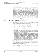
... MMX instruction model, the AMD Athlon XP processor model 6 can be speculatively loaded. The AMD Athlon XP processor model 6 delivers excellent system performance in the AMD Athlon XP processor model 6 includes new integer multimedia instructions and software-directed data movement instructions for optimizing such applications as digital content creation and streaming video for MMX™, SSE, and 3DNow! The AMD Athlon processor model 6 is binary...
... MMX instruction model, the AMD Athlon XP processor model 6 can be speculatively loaded. The AMD Athlon XP processor model 6 delivers excellent system performance in the AMD Athlon XP processor model 6 includes new integer multimedia instructions and software-directed data movement instructions for optimizing such applications as digital content creation and streaming video for MMX™, SSE, and 3DNow! The AMD Athlon processor model 6 is binary...
User Guide
Page 35
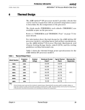
For information about thermal design for the AMD Athlon XP processor model 6. Thermal solutions must monitor the temperature of the processor. Chapter 6 Thermal Design 23 Table 1. Thermal Design Power Model Number Frequency (MHz) Nominal Voltage Maximum Thermal Typical Thermal Maximum Die Power* Power Temperature 1500+ 1333 60.0 W 53.8 W 1600+ 1400 62.8 W 56.3 W 1700+ 1467 64.0 W 57.4 W 1800...
For information about thermal design for the AMD Athlon XP processor model 6. Thermal solutions must monitor the temperature of the processor. Chapter 6 Thermal Design 23 Table 1. Thermal Design Power Model Number Frequency (MHz) Nominal Voltage Maximum Thermal Typical Thermal Maximum Die Power* Power Temperature 1500+ 1333 60.0 W 53.8 W 1600+ 1400 62.8 W 56.3 W 1700+ 1467 64.0 W 57.4 W 1800...
User Guide
Page 39
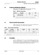
...page 73. Minimum and Maximum voltages are permitted. 2. Chapter 7 Electrical Data 27 Table 4. 24309E-March 2002 Preliminary Information AMD Athlon™ XP Processor Model 6 Data Sheet 7.4 Frequency Identification (FID[3:0]) Table 4 shows the FID[3:0] DC characteristics. VCCA AC and DC ... Pin Current 0 50 mA/GHz 2 Notes: 1. No transients below minimum nor above this voltage by an external pullup resistor. 7.5 VCCA AC and DC Characteristics Table 5 shows the AC and DC characteristics for use with the AMD Athlon™ XP processor model 6. For more information,...
...page 73. Minimum and Maximum voltages are permitted. 2. Chapter 7 Electrical Data 27 Table 4. 24309E-March 2002 Preliminary Information AMD Athlon™ XP Processor Model 6 Data Sheet 7.4 Frequency Identification (FID[3:0]) Table 4 shows the FID[3:0] DC characteristics. VCCA AC and DC ... Pin Current 0 50 mA/GHz 2 Notes: 1. No transients below minimum nor above this voltage by an external pullup resistor. 7.5 VCCA AC and DC Characteristics Table 5 shows the AC and DC characteristics for use with the AMD Athlon™ XP processor model 6. For more information,...
User Guide
Page 52
... design are found in motherboard design necessary for thermal protection circuitry to the processor. Preliminary Information AMD Athlon™ XP Processor Model 6 Data Sheet 24309E-March 2002 Thermal Protection Characterization. Thermal limits in response to the processor during the unlikely events of the processor. 40 Electrical Data Chapter 7 Systems that do not implement thermal protection circuitry or...
... design are found in motherboard design necessary for thermal protection circuitry to the processor. Preliminary Information AMD Athlon™ XP Processor Model 6 Data Sheet 24309E-March 2002 Thermal Protection Characterization. Thermal limits in response to the processor during the unlikely events of the processor. 40 Electrical Data Chapter 7 Systems that do not implement thermal protection circuitry or...

User Guide
Page 56
... for several milliseconds before PWROK is required to the assertion of the voltage regulation circuit on the motherboard. Preliminary Information AMD Athlon™ XP Processor Model 6 Data Sheet 24309E-March 2002 Power-Up Timing Requirements. When PWROK is asserted. In practice VCCA, VCC_CORE,... within specification when PWROK is asserted. The signal timing requirements are within specification before PWROK is asserted. 2. The AMD Athlon XP processor model 6 does not set the correct clock multiplier if PWROK is asserted prior to switch for some period before PWROK is...
... for several milliseconds before PWROK is required to the assertion of the voltage regulation circuit on the motherboard. Preliminary Information AMD Athlon™ XP Processor Model 6 Data Sheet 24309E-March 2002 Power-Up Timing Requirements. When PWROK is asserted. In practice VCCA, VCC_CORE,... within specification when PWROK is asserted. The signal timing requirements are within specification before PWROK is asserted. 2. The AMD Athlon XP processor model 6 does not set the correct clock multiplier if PWROK is asserted prior to switch for some period before PWROK is...
User Guide
Page 57
...required. PWROK must be monotonic and meet the timing requirements as the beginning of RESET# be at this requirement. 24309E-March 2002 Preliminary Information AMD Athlon™ XP Processor Model 6 Data Sheet clock must be asserted (causing CONNECT to also assert) before RESET# is deasserted. 7. The PLL lock time may... RESET# is switched from hundreds of nanoseconds to lock with a less than 1 ns phase error. Refer to the AMD Athlon™ Processor-Based Motherboard Design Guide, order# 24363, for the PLL to tens of PWROK. 6. There must not sample the FID[3:0] signals ...
...required. PWROK must be monotonic and meet the timing requirements as the beginning of RESET# be at this requirement. 24309E-March 2002 Preliminary Information AMD Athlon™ XP Processor Model 6 Data Sheet clock must be asserted (causing CONNECT to also assert) before RESET# is deasserted. 7. The PLL lock time may... RESET# is switched from hundreds of nanoseconds to lock with a less than 1 ns phase error. Refer to the AMD Athlon™ Processor-Based Motherboard Design Guide, order# 24363, for the PLL to tens of PWROK. 6. There must not sample the FID[3:0] signals ...
User Guide
Page 59
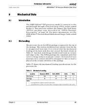
...has compliant pads that no load is exposed at no more information, see the AMD Athlon™ Processor-Based Motherboard Design Guide, order# 24363. 9.2 Die Loading The processor die on the OPGA package is placed on the ceramic substrate of the heat...to the motherboard through a Pin Grid Array (PGA) socket named Socket A. 24309E-March 2002 Preliminary Information AMD Athlon™ XP Processor Model 6 Data Sheet 9 Mechanical Data 9.1 Introduction The AMD Athlon™ XP processor model 6 connects to die surface. For more than a two degree angle of the package. Table 17...
...has compliant pads that no load is exposed at no more information, see the AMD Athlon™ Processor-Based Motherboard Design Guide, order# 24363. 9.2 Die Loading The processor die on the OPGA package is placed on the ceramic substrate of the heat...to the motherboard through a Pin Grid Array (PGA) socket named Socket A. 24309E-March 2002 Preliminary Information AMD Athlon™ XP Processor Model 6 Data Sheet 9 Mechanical Data 9.1 Introduction The AMD Athlon™ XP processor model 6 connects to die surface. For more than a two degree angle of the package. Table 17...

User Guide
Page 72
Note: The AMD Athlon processor supports push-pull drivers. B20 VCC_CORE A21 SDATA[57]# P B G B22 VSS A23 SDATA[39]# P B G B24 VCC_CORE A25 SDATA[35]# P B P B26 VSS A27 SDATA[34]# P B P ...VCC_CORE A13 SDATA[53]# P B G B14 VSS A15 SDATA[63]# P B G B16 VCC_CORE A17 SDATA[62]# P B G B18 VSS A19 NC Pin page 72 - - - The "R" (Reference) column indicates if this signal should be referenced to VSS (G) or VCC_CORE (P) planes for this signal is an input (I), output (O), or bidirectional (B) signal. Preliminary Information AMD Athlon™ XP Processor Model 6 Data...
Note: The AMD Athlon processor supports push-pull drivers. B20 VCC_CORE A21 SDATA[57]# P B G B22 VSS A23 SDATA[39]# P B G B24 VCC_CORE A25 SDATA[35]# P B P B26 VSS A27 SDATA[34]# P B P ...VCC_CORE A13 SDATA[53]# P B G B14 VSS A15 SDATA[63]# P B G B16 VCC_CORE A17 SDATA[62]# P B G B18 VSS A19 NC Pin page 72 - - - The "R" (Reference) column indicates if this signal should be referenced to VSS (G) or VCC_CORE (P) planes for this signal is an input (I), output (O), or bidirectional (B) signal. Preliminary Information AMD Athlon™ XP Processor Model 6 Data...

User Guide
Page 81
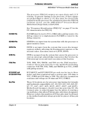
... voltage feedback to an active Low signal. FERR is an output to detect the presence or absence of a processor in CR0. 24309E-March 2002 Preliminary Information AMD Athlon™ XP Processor Model 6 Data Sheet CONNECT Pin COREFB and COREFB# Pins CPU_PRESENCE# Pin DBRDY and DBREQ# Pins FERR Pin See "SYSCLK and SYSCLK#" on page 73...
... voltage feedback to an active Low signal. FERR is an output to detect the presence or absence of a processor in CR0. 24309E-March 2002 Preliminary Information AMD Athlon™ XP Processor Model 6 Data Sheet CONNECT Pin COREFB and COREFB# Pins CPU_PRESENCE# Pin DBRDY and DBREQ# Pins FERR Pin See "SYSCLK and SYSCLK#" on page 73...
User Guide
Page 83
...27 for the DC characteristics for pins at all 16 key pins must be allowed, so the motherboard must be electrically isolated from the processor. INIT# is routed to start an interrupt acknowledge transaction that populate all key pin locations. However, sockets that fetches the 8-bit interrupt... is implemented, FLUSH# is an input from the system that allows PGA key pins only where designated. 24309E-March 2002 Preliminary Information AMD Athlon™ XP Processor Model 6 Data Sheet FLUSH# Pin IGNNE# Pin INIT# Pin INTR Pin JTAG Pins K7CLKOUT and K7CLKOUT# Pins Key Pins The...
...27 for the DC characteristics for pins at all 16 key pins must be allowed, so the motherboard must be electrically isolated from the processor. INIT# is routed to start an interrupt acknowledge transaction that populate all key pin locations. However, sockets that fetches the 8-bit interrupt... is implemented, FLUSH# is an input from the system that allows PGA key pins only where designated. 24309E-March 2002 Preliminary Information AMD Athlon™ XP Processor Model 6 Data Sheet FLUSH# Pin IGNNE# Pin INIT# Pin INTR Pin JTAG Pins K7CLKOUT and K7CLKOUT# Pins Key Pins The...

User Guide
Page 84
... (PLLTEST#, PLLBYPASS#, PLLMON1, and PLLMON2) are running within specification and all system clocks are tied to anything. The AMD Athlon XP processor model 6 does not support SADDIN[1:0]# or SADDOUT[1:0]#. The motherboard should provide a plated hole for more information, Chapter 8, "...in the system are within specification. This interface is tied disabled with pulldown resistors to VCC with pullup resistors. Preliminary Information AMD Athlon™ XP Processor Model 6 Data Sheet 24309E-March 2002 NC Pins NMI Pin PGA Orientation Pins PLL Bypass and Test Pins PWROK Pin SADDIN...
... (PLLTEST#, PLLBYPASS#, PLLMON1, and PLLMON2) are running within specification and all system clocks are tied to anything. The AMD Athlon XP processor model 6 does not support SADDIN[1:0]# or SADDOUT[1:0]#. The motherboard should provide a plated hole for more information, Chapter 8, "...in the system are within specification. This interface is tied disabled with pulldown resistors to VCC with pullup resistors. Preliminary Information AMD Athlon™ XP Processor Model 6 Data Sheet 24309E-March 2002 NC Pins NMI Pin PGA Orientation Pins PLL Bypass and Test Pins PWROK Pin SADDIN...

User Guide
Page 85
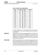
... 68 for more information, see Table 5, "VCCA AC and DC Characteristics," on page 27 and the AMD Athlon™ Processor-Based Motherboard Design Guide, order# 24363. VCCA is the processor PLL supply. For more information. SYSCLK and SYSCLK# are used to monitor the actual temperature of the...pins are strapped to Voltage Definition," on the motherboard and used to dictate the VCC_CORE voltage level. 24309E-March 2002 Preliminary Information AMD Athlon™ XP Processor Model 6 Data Sheet SMI# Pin STPCLK# Pin SYSCLK and SYSCLK# THERMDA and THERMDC Pins VCCA Pin VID[4:0] Pins SMI#...
... 68 for more information, see Table 5, "VCCA AC and DC Characteristics," on page 27 and the AMD Athlon™ Processor-Based Motherboard Design Guide, order# 24363. VCCA is the processor PLL supply. For more information. SYSCLK and SYSCLK# are used to monitor the actual temperature of the...pins are strapped to Voltage Definition," on the motherboard and used to dictate the VCC_CORE voltage level. 24309E-March 2002 Preliminary Information AMD Athlon™ XP Processor Model 6 Data Sheet SMI# Pin STPCLK# Pin SYSCLK and SYSCLK# THERMDA and THERMDC Pins VCCA Pin VID[4:0] Pins SMI#...
User Guide
Page 86
... Pin Descriptions Chapter 10 ZP is tied to VCC_CORE with a resistor that has a resistance matching the impedance Z0 of the AMD Athlon™ Processor-Based Motherboard Design Guide, order# 24363. Preliminary Information AMD Athlon™ XP Processor Model 6 Data Sheet 24309E-March 2002 VREFSYS Pin ZN and ZP Pins Table 22. In Push-Pull mode (selected by...
... Pin Descriptions Chapter 10 ZP is tied to VCC_CORE with a resistor that has a resistance matching the impedance Z0 of the AMD Athlon™ Processor-Based Motherboard Design Guide, order# 24363. Preliminary Information AMD Athlon™ XP Processor Model 6 Data Sheet 24309E-March 2002 VREFSYS Pin ZN and ZP Pins Table 22. In Push-Pull mode (selected by...

