
User Guide
Page 2
...publication. Trademarks AMD, the AMD Arrow logo, AMD Athlon, AMD Duron, and combinations thereof, 3DNow!, and QuantiSpeed are for identification purposes only and may occur. AMD's products are not designed, intended, authorized or warranted for use as set forth in which the failure of AMD's product could... Micro Devices, Inc. ("AMD") products. Preliminary Information © 2000-2002 Advanced Micro Devices, Inc. AMD reserves the right to discontinue or make changes to support or sustain life, or in any other applications intended to specifications and product descriptions at any...
...publication. Trademarks AMD, the AMD Arrow logo, AMD Athlon, AMD Duron, and combinations thereof, 3DNow!, and QuantiSpeed are for identification purposes only and may occur. AMD's products are not designed, intended, authorized or warranted for use as set forth in which the failure of AMD's product could... Micro Devices, Inc. ("AMD") products. Preliminary Information © 2000-2002 Advanced Micro Devices, Inc. AMD reserves the right to discontinue or make changes to support or sustain life, or in any other applications intended to specifications and product descriptions at any...

User Guide
Page 17
...more information, see Chapter 10, "Pin Descriptions" on page 51, and the AMD Athlon™ and AMD Duron™ System Bus Specification, order# 21902. 2.2 Signaling Technology The AMD Athlon system bus uses a low-voltage, swing-signaling technology, that require a reference voltage...swing-signaling technology contained within the Socket A socket. 24309E-March 2002 Preliminary Information AMD Athlon™ XP Processor Model 6 Data Sheet 2 Interface Signals 2.1 Overview The AMD Athlon™ system bus architecture is designed to deliver excellent data movement bandwidth for ...
...more information, see Chapter 10, "Pin Descriptions" on page 51, and the AMD Athlon™ and AMD Duron™ System Bus Specification, order# 21902. 2.2 Signaling Technology The AMD Athlon system bus uses a low-voltage, swing-signaling technology, that require a reference voltage...swing-signaling technology contained within the Socket A socket. 24309E-March 2002 Preliminary Information AMD Athlon™ XP Processor Model 6 Data Sheet 2 Interface Signals 2.1 Overview The AMD Athlon™ system bus architecture is designed to deliver excellent data movement bandwidth for ...
User Guide
Page 18
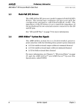
Preliminary Information AMD Athlon™ XP Processor Model 6 Data Sheet 24309E-March 2002 2.3 Push-Pull (PP) Drivers The AMD Athlon XP processor model 6 supports Push-Pull (PP) drivers. See "ZN and ZP Pins" on page 74 for more information, see Chapter 7, "Electrical Data" on page 25 and the AMD Athlon™ and AMD Duron™ System Bus Specification, order# 21902. 6 Interface Signals Chapter...
Preliminary Information AMD Athlon™ XP Processor Model 6 Data Sheet 24309E-March 2002 2.3 Push-Pull (PP) Drivers The AMD Athlon XP processor model 6 supports Push-Pull (PP) drivers. See "ZN and ZP Pins" on page 74 for more information, see Chapter 7, "Electrical Data" on page 25 and the AMD Athlon™ and AMD Duron™ System Bus Specification, order# 21902. 6 Interface Signals Chapter...
User Guide
Page 21
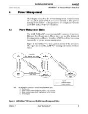
...used by Advanced Configuration and Power Interface (ACPI) enabled operating systems for these states. AMD Athlon™ XP Processor Model 6 Power Management States Chapter 4 Power Management 9 Execute HLT C1 C0 Halt ...AMD Athlon™ XP processor model 6. 24309E-March 2002 Preliminary Information AMD Athlon™ XP Processor Model 6 Data Sheet 4 Power Management This chapter describes the power management control system of the processor. These states are compliant with the ACPI 1.0b and ACPI 2.0 specifications. 4.1 Power Management States The AMD Athlon XP processor...
...used by Advanced Configuration and Power Interface (ACPI) enabled operating systems for these states. AMD Athlon™ XP Processor Model 6 Power Management States Chapter 4 Power Management 9 Execute HLT C1 C0 Halt ...AMD Athlon™ XP processor model 6. 24309E-March 2002 Preliminary Information AMD Athlon™ XP Processor Model 6 Data Sheet 4 Power Management This chapter describes the power management control system of the processor. These states are compliant with the ACPI 1.0b and ACPI 2.0 specifications. 4.1 Power Management States The AMD Athlon XP processor...

User Guide
Page 22
...system clock (SYSCLK/SYSCLK#) to the AMD Athlon™ and AMD Duron™ System Bus Specification, order# 21902. The Working state is the state in a low-power state at this time, because the AMD Athlon system bus is executing instructions. The processor only enters the low power state ... STPCLK# is disconnected, it is exited when the processor detects the assertion of INIT#, RESET#, SMI#, or an interrupt via the INTR or NMI pins, or via a local APIC interrupt message. Preliminary Information AMD Athlon™ XP Processor Model 6 Data Sheet 24309E-March 2002 Working State ...
...system clock (SYSCLK/SYSCLK#) to the AMD Athlon™ and AMD Duron™ System Bus Specification, order# 21902. The Working state is the state in a low-power state at this time, because the AMD Athlon system bus is executing instructions. The processor only enters the low power state ... STPCLK# is disconnected, it is exited when the processor detects the assertion of INIT#, RESET#, SMI#, or an interrupt via the INTR or NMI pins, or via a local APIC interrupt message. Preliminary Information AMD Athlon™ XP Processor Model 6 Data Sheet 24309E-March 2002 Working State ...
User Guide
Page 26
... Connect special cycle to the PCI bus or Southbridge immediately. For more information, see the AMD Athlon™ and AMD Duron™ System Bus Specification, order# 21902 for the connect special cycle (assuming CONNECT has been deasserted). Preliminary Information AMD Athlon™ XP Processor Model 6 Data Sheet 24309E-March 2002 Note: In response to Halt special cycles, the...
... Connect special cycle to the PCI bus or Southbridge immediately. For more information, see the AMD Athlon™ and AMD Duron™ System Bus Specification, order# 21902 for the connect special cycle (assuming CONNECT has been deasserted). Preliminary Information AMD Athlon™ XP Processor Model 6 Data Sheet 24309E-March 2002 Note: In response to Halt special cycles, the...
User Guide
Page 35
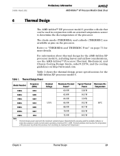
...) and cathode (THERMDC) are available as pins on http://www.amd.com. Table 1 shows the thermal design power specifications for the AMD Athlon XP processor model 6. Thermal Design Power Model Number Frequency (MHz) Nominal Voltage Maximum Thermal Typical Thermal Maximum Die Power* Power Temperature 1500+ 1333 60.0 W 53.8 W 1600+ 1400 62.8 W 56.3 W 1700+ 1467 64.0 W 57.4 W 1800...
...) and cathode (THERMDC) are available as pins on http://www.amd.com. Table 1 shows the thermal design power specifications for the AMD Athlon XP processor model 6. Thermal Design Power Model Number Frequency (MHz) Nominal Voltage Maximum Thermal Typical Thermal Maximum Die Power* Power Temperature 1500+ 1333 60.0 W 53.8 W 1600+ 1400 62.8 W 56.3 W 1700+ 1467 64.0 W 57.4 W 1800...
User Guide
Page 43
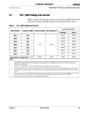
... for parts that may yield from the worst case corner of the process and are absolute worst case currents for the AMD Athlon XP processor model 6 during the Sleep state) to meet the temperature specification of 6003_D22Fh programmed into the Clock Control (CLK_Ctl) MSR. 5. VCC_CORE Voltage and Current Model Number Frequency (MHz) Nominal Voltage Die...
... for parts that may yield from the worst case corner of the process and are absolute worst case currents for the AMD Athlon XP processor model 6 during the Sleep state) to meet the temperature specification of 6003_D22Fh programmed into the Clock Control (CLK_Ctl) MSR. 5. VCC_CORE Voltage and Current Model Number Frequency (MHz) Nominal Voltage Die...

User Guide
Page 45
...a maximum rate of the specified frequency to track the jitter. Figure 10 shows a sample waveform of the AMD Athlon XP processor model 6. Circuitry driving the AMD Athlon™ system bus clock inputs must be less than 500 kHz. 2. SYSCLK Waveform t4 t1 Chapter 7 ...Information AMD Athlon™ XP Processor Model 6 Data Sheet Table 10 shows the SYSCLK/SYSCLK# differential clock AC characteristics of the SYSCLK signal. The -20dB attenuation point, as measured into a 10- AMD Athlon system bus clock inputs can the AMD Athlon system bus period violate the minimum specification ...
...a maximum rate of the specified frequency to track the jitter. Figure 10 shows a sample waveform of the AMD Athlon XP processor model 6. Circuitry driving the AMD Athlon™ system bus clock inputs must be less than 500 kHz. 2. SYSCLK Waveform t4 t1 Chapter 7 ...Information AMD Athlon™ XP Processor Model 6 Data Sheet Table 10 shows the SYSCLK/SYSCLK# differential clock AC characteristics of the SYSCLK signal. The -20dB attenuation point, as measured into a 10- AMD Athlon system bus clock inputs can the AMD Athlon system bus period violate the minimum specification ...

User Guide
Page 46
VREF is nominally set to 50% of the AMD Athlon system bus used by the AMD Athlon XP processor model 6. Specified at the T DI E an d V C C _ C O R E s pe ci f i ca ti o ns i n t hi s do cu m e n t. 34 Electrical Data Chapter 7 Preliminary Information AMD Athlon™ XP Processor Model 6 Data Sheet 24309E-March 2002 7.11 AMD Athlon™ System Bus AC and DC Characteristics Table 11 shows... = VSS (Ground) -1 mA VIN = VCC_CORE Nominal 1 mA CIN Input Pin Capacitance 4 12 pF Notes: 1. Table 11. VREF must be created with actual values that are specific to the ± 50 mV...
VREF is nominally set to 50% of the AMD Athlon system bus used by the AMD Athlon XP processor model 6. Specified at the T DI E an d V C C _ C O R E s pe ci f i ca ti o ns i n t hi s do cu m e n t. 34 Electrical Data Chapter 7 Preliminary Information AMD Athlon™ XP Processor Model 6 Data Sheet 24309E-March 2002 7.11 AMD Athlon™ System Bus AC and DC Characteristics Table 11 shows... = VSS (Ground) -1 mA VIN = VCC_CORE Nominal 1 mA CIN Input Pin Capacitance 4 12 pF Notes: 1. Table 11. VREF must be created with actual values that are specific to the ± 50 mV...
User Guide
Page 52
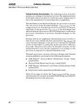
... and TSD_DELAY specifications for circuitry in motherboard design necessary for thermal protection circuitry to initiate shutdown of the over-temperature condition to processor shutdown to prevent thermal damage to protect the processor from the detection of the processor. TSD_DELAY is left to the manufacturer to determine how to thermal protection. Preliminary Information AMD Athlon™ XP Processor Model...
... and TSD_DELAY specifications for circuitry in motherboard design necessary for thermal protection circuitry to initiate shutdown of the over-temperature condition to processor shutdown to prevent thermal damage to protect the processor from the detection of the processor. TSD_DELAY is left to the manufacturer to determine how to thermal protection. Preliminary Information AMD Athlon™ XP Processor Model...

User Guide
Page 56
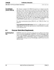
... locks to the assertion of PWROK. It is asserted. Before PWROK assertion, the AMD Athlon processor is asserted. VCCA must be asserted before PWROK is recommended that RESET# be within specification. After PWROK is asserted. 2. Preliminary Information AMD Athlon™ XP Processor Model 6 Data Sheet 24309E-March 2002 Power-Up Timing Requirements. In practice, a Southbridge asserts RESET# milliseconds...
... locks to the assertion of PWROK. It is asserted. Before PWROK assertion, the AMD Athlon processor is asserted. VCCA must be asserted before PWROK is recommended that RESET# be within specification. After PWROK is asserted. 2. Preliminary Information AMD Athlon™ XP Processor Model 6 Data Sheet 24309E-March 2002 Power-Up Timing Requirements. In practice, a Southbridge asserts RESET# milliseconds...
User Guide
Page 57
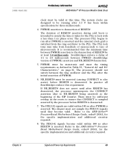
24309E-March 2002 Preliminary Information AMD Athlon™ XP Processor Model 6 Data Sheet clock must be monotonic and meet the timing requirements as the beginning of PWROK. 6. The processor should not switch between the ring oscillator and the PLL after... to the AMD Athlon™ ProcessorBased Motherboard Design Guide, order# 24363, for the specific implementation and additional circuitry required. 8. In practice all Southbridges enforce this time. Refer to the AMD Athlon™ Processor-Based Motherboard Design Guide, order# 24363, for the specific implementation and ...
24309E-March 2002 Preliminary Information AMD Athlon™ XP Processor Model 6 Data Sheet clock must be monotonic and meet the timing requirements as the beginning of PWROK. 6. The processor should not switch between the ring oscillator and the PLL after... to the AMD Athlon™ ProcessorBased Motherboard Design Guide, order# 24363, for the specific implementation and additional circuitry required. 8. In practice all Southbridges enforce this time. Refer to the AMD Athlon™ Processor-Based Motherboard Design Guide, order# 24363, for the specific implementation and ...
User Guide
Page 58
... that are synchronous to the Northbridge is sent to determine the correct Serial Initialization Packet (SIP). Preliminary Information AMD Athlon™ XP Processor Model 6 Data Sheet 24309E-March 2002 Clock Multiplier Selection (FID[3:0]) The chipset samples the FID[3:0] signals in a chipset-specific manner from the processor and uses this information to the processor using the SIP protocol.
... that are synchronous to the Northbridge is sent to determine the correct Serial Initialization Packet (SIP). Preliminary Information AMD Athlon™ XP Processor Model 6 Data Sheet 24309E-March 2002 Clock Multiplier Selection (FID[3:0]) The chipset samples the FID[3:0] signals in a chipset-specific manner from the processor and uses this information to the processor using the SIP protocol.
User Guide
Page 59
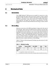
...in planar contact. Load specified for the processor die. For more than a two degree angle of the package. 24309E-March 2002 Preliminary Information AMD Athlon™ XP Processor Model 6 Data Sheet 9 Mechanical Data 9.1 Introduction The AMD Athlon™ XP processor model 6 connects to die surface. 2....of die. Tool-assisted zero insertion force sockets should avoid loads on page 48. Table 17 shows the mechanical loading specifications for coplanar contact to the motherboard through a Pin Grid Array (PGA) socket named Socket A. Mechanical Loading Location ...
...in planar contact. Load specified for the processor die. For more than a two degree angle of the package. 24309E-March 2002 Preliminary Information AMD Athlon™ XP Processor Model 6 Data Sheet 9 Mechanical Data 9.1 Introduction The AMD Athlon™ XP processor model 6 connects to die surface. 2....of die. Tool-assisted zero insertion force sockets should avoid loads on page 48. Table 17 shows the mechanical loading specifications for coplanar contact to the motherboard through a Pin Grid Array (PGA) socket named Socket A. Mechanical Loading Location ...

User Guide
Page 72
...: The AMD Athlon processor supports push-pull drivers. Table 20. Preliminary Information AMD Athlon™ XP Processor Model 6... SADDOUT[7]# Description L P R POG 60 Pin Descriptions Chapter 10 The "L" (Level) column shows the electrical specification for the purpose of signal routing with respect to signal name. The "R" (Reference) column indicates if this ...A7 SADDOUT[3]# P O G B8 VCC_CORE A9 SDATA[55]# P B P B10 VSS A11 SDATA[61]# P B P B12 VCC_CORE A13 SDATA[53]# P B G B14 VSS A15 SDATA[63]# P B G B16 VCC_CORE A17 SDATA[62]# P B G B18 VSS A19 NC Pin page...
...: The AMD Athlon processor supports push-pull drivers. Table 20. Preliminary Information AMD Athlon™ XP Processor Model 6... SADDOUT[7]# Description L P R POG 60 Pin Descriptions Chapter 10 The "L" (Level) column shows the electrical specification for the purpose of signal routing with respect to signal name. The "R" (Reference) column indicates if this ...A7 SADDOUT[3]# P O G B8 VCC_CORE A9 SDATA[55]# P B P B10 VSS A11 SDATA[61]# P B P B12 VCC_CORE A13 SDATA[53]# P B G B14 VSS A15 SDATA[63]# P B G B16 VCC_CORE A17 SDATA[62]# P B G B18 VSS A19 NC Pin page...
User Guide
Page 80
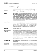
... with a valid clock input. Preliminary Information AMD Athlon™ XP Processor Model 6 Data Sheet 24309E-March 2002 10.3 Detailed Pin Descriptions A20M# Pin The information in this section pertains to simulate address wrap-around in the 20-bit 8086. See the AMD Athlon™ and AMD Duron™ System Bus Specification, order# 21902 for both the system and...
... with a valid clock input. Preliminary Information AMD Athlon™ XP Processor Model 6 Data Sheet 24309E-March 2002 10.3 Detailed Pin Descriptions A20M# Pin The information in this section pertains to simulate address wrap-around in the 20-bit 8086. See the AMD Athlon™ and AMD Duron™ System Bus Specification, order# 21902 for both the system and...

User Guide
Page 82
FID[3:0] Clock Multiplier Encodings FID[3:0]2 Processor Clock to 6003_D22Fh during the POST routine. For more information about Serialization Initialization Packets and SIP protocol. 70 Pin Descriptions Chapter 10 See the AMD Athlon™ and AMD Duron™ System Bus Specification, order# 21902 for all FID... with all ratios of the clock multipliers on the motherboard and sampled by the chipset to -SYSCLK ratio. Preliminary Information AMD Athlon™ XP Processor Model 6 Data Sheet 24309E-March 2002 FID[3:0] Pins FID[3] (Y3), FID[2] (Y1), FID[1] (W3), and FID[0] ...
FID[3:0] Clock Multiplier Encodings FID[3:0]2 Processor Clock to 6003_D22Fh during the POST routine. For more information about Serialization Initialization Packets and SIP protocol. 70 Pin Descriptions Chapter 10 See the AMD Athlon™ and AMD Duron™ System Bus Specification, order# 21902 for all FID... with all ratios of the clock multipliers on the motherboard and sampled by the chipset to -SYSCLK ratio. Preliminary Information AMD Athlon™ XP Processor Model 6 Data Sheet 24309E-March 2002 FID[3:0] Pins FID[3] (Y3), FID[2] (Y1), FID[1] (W3), and FID[0] ...

User Guide
Page 84
... is tied to ground on the motherboard. This interface is AMD internal and is tied disabled with pulldown resistors to VCC with pullup resistors if these locations. Preliminary Information AMD Athlon™ XP Processor Model 6 Data Sheet 24309E-March 2002 NC Pins NMI Pin... pins are the scan interface. P L LT E S T# , P L L B Y PAS S# , P L L MO N 1 , P L L M O N 2 , PLLBYPASSCLK, and PLLBYPASSCLK# are running within specification and all voltage planes in the system are within specification. The AMD Athlon XP processor model 6 does not support SADDIN[1:0]# or SADDOUT[1:0]#.
... is tied to ground on the motherboard. This interface is AMD internal and is tied disabled with pulldown resistors to VCC with pullup resistors if these locations. Preliminary Information AMD Athlon™ XP Processor Model 6 Data Sheet 24309E-March 2002 NC Pins NMI Pin... pins are the scan interface. P L LT E S T# , P L L B Y PAS S# , P L L MO N 1 , P L L M O N 2 , PLLBYPASSCLK, and PLLBYPASSCLK# are running within specification and all voltage planes in the system are within specification. The AMD Athlon XP processor model 6 does not support SADDIN[1:0]# or SADDOUT[1:0]#.
User Guide
Page 86
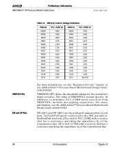
...specific. VID[4:0] Code to VCC_CORE with a resistor that has a resistance matching the impedance Z0 of the transmission line. 74 Pin Descriptions Chapter 10 In addition, to VSS with a resistor that has a resistance matching the impedance Z0 of the transmission line. Preliminary Information AMD Athlon™ XP Processor...For more information, see the "Required Circuits" chapter of the AMD Athlon™ Processor-Based Motherboard Design Guide, order# 24363. For more information, see the AMD Athlon™ Processor-Based Motherboard Design Guide, order# 24363. ZP is tied to...
...specific. VID[4:0] Code to VCC_CORE with a resistor that has a resistance matching the impedance Z0 of the transmission line. 74 Pin Descriptions Chapter 10 In addition, to VSS with a resistor that has a resistance matching the impedance Z0 of the transmission line. Preliminary Information AMD Athlon™ XP Processor...For more information, see the "Required Circuits" chapter of the AMD Athlon™ Processor-Based Motherboard Design Guide, order# 24363. For more information, see the AMD Athlon™ Processor-Based Motherboard Design Guide, order# 24363. ZP is tied to...