User Guide
Page 14
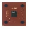
...-Instruction Multiple-Data (SIMD) operations based on the MMX instruction model, the AMD Athlon XP processor model 6 can be speculatively loaded. The AMD Athlon processor model 6 is binary-compatible with existing x86 software and backwards compatible with applications...clock cycle. Preliminary Information AMD Athlon™ XP Processor Model 6 Data Sheet 24309E-March 2002 The AMD Athlon XP processor model 6 is compatible with motherboards based on Socket A. The AMD Athlon XP processor model 6 delivers excellent system performance in the AMD Athlon XP processor model 6 includes new...
...-Instruction Multiple-Data (SIMD) operations based on the MMX instruction model, the AMD Athlon XP processor model 6 can be speculatively loaded. The AMD Athlon processor model 6 is binary-compatible with existing x86 software and backwards compatible with applications...clock cycle. Preliminary Information AMD Athlon™ XP Processor Model 6 Data Sheet 24309E-March 2002 The AMD Athlon XP processor model 6 is compatible with motherboards based on Socket A. The AMD Athlon XP processor model 6 delivers excellent system performance in the AMD Athlon XP processor model 6 includes new...

User Guide
Page 17
24309E-March 2002 Preliminary Information AMD Athlon™ XP Processor Model 6 Data Sheet 2 Interface Signals 2.1 Overview The AMD Athlon™ system bus architecture is used at the receiver to bring the signal past the input threshold. In addition, the system ...signal is asserted or deasserted by enterprise-class application software. The signals are not needed because the driver is impedance-matched to the motherboard and a high impedance reflection is used by the receivers to provide larger noise margins, reduced ringing, and variable voltage levels. Chapter 2 ...
24309E-March 2002 Preliminary Information AMD Athlon™ XP Processor Model 6 Data Sheet 2 Interface Signals 2.1 Overview The AMD Athlon™ system bus architecture is used at the receiver to bring the signal past the input threshold. In addition, the system ...signal is asserted or deasserted by enterprise-class application software. The signals are not needed because the driver is impedance-matched to the motherboard and a high impedance reflection is used by the receivers to provide larger noise margins, reduced ringing, and variable voltage levels. Chapter 2 ...
User Guide
Page 18
... of the motherboard by two external resistors connected to the ZN and ZP pins. See "ZN and ZP Pins" on page 25 and the AMD Athlon™ and AMD Duron™ System Bus Specification, order# 21902. 6 Interface Signals Chapter 2 Preliminary Information AMD Athlon™ XP Processor Model 6 Data Sheet 24309E-March 2002 2.3 Push-Pull (PP) Drivers The AMD Athlon XP processor model...
... of the motherboard by two external resistors connected to the ZN and ZP pins. See "ZN and ZP Pins" on page 25 and the AMD Athlon™ and AMD Duron™ System Bus Specification, order# 21902. 6 Interface Signals Chapter 2 Preliminary Information AMD Athlon™ XP Processor Model 6 Data Sheet 24309E-March 2002 2.3 Push-Pull (PP) Drivers The AMD Athlon XP processor model...
User Guide
Page 39
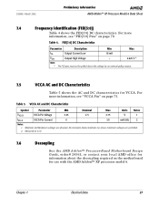
... the motherboard for VCCA. Chapter 7 Electrical Data 27 24309E-March 2002 Preliminary Information AMD Athlon™ XP Processor Model 6 Data Sheet 7.4 Frequency Identification (FID[3:0]) Table 4 shows the FID[3:0] DC characteristics. VCCA AC and DC Characteristics Symbol Parameter Min Nominal Max Units Notes VVCCA VCCA Pin Voltage 2.25 2.5 2.75 V 1 IVCCA VCCA Pin Current 0 50 mA/GHz 2 Notes...
... the motherboard for VCCA. Chapter 7 Electrical Data 27 24309E-March 2002 Preliminary Information AMD Athlon™ XP Processor Model 6 Data Sheet 7.4 Frequency Identification (FID[3:0]) Table 4 shows the FID[3:0] DC characteristics. VCCA AC and DC Characteristics Symbol Parameter Min Nominal Max Units Notes VVCCA VCCA Pin Voltage 2.25 2.5 2.75 V 1 IVCCA VCCA Pin Current 0 50 mA/GHz 2 Notes...

User Guide
Page 46
AMD Athlon™ System Bus DC Characteristics Symbol...VCC_CORE Nominal 1 mA CIN Input Pin Capacitance 4 12 pF Notes: 1. Preliminary Information AMD Athlon™ XP Processor Model 6 Data Sheet 24309E-March 2002 7.11 AMD Athlon™ System Bus AC and DC Characteristics Table 11 shows the DC characteristics of VCC_CORE ...to the ± 50 mV specification listed above. 2. VREF must be created with actual values that are specific to 50% of the AMD Athlon system bus used by the AMD Athlon XP processor model 6. Specified at the T DI E an d V C C _ C O R E s pe ci f i ca ti ...
AMD Athlon™ System Bus DC Characteristics Symbol...VCC_CORE Nominal 1 mA CIN Input Pin Capacitance 4 12 pF Notes: 1. Preliminary Information AMD Athlon™ XP Processor Model 6 Data Sheet 24309E-March 2002 7.11 AMD Athlon™ System Bus AC and DC Characteristics Table 11 shows the DC characteristics of VCC_CORE ...to the ± 50 mV specification listed above. 2. VREF must be created with actual values that are specific to 50% of the AMD Athlon system bus used by the AMD Athlon XP processor model 6. Specified at the T DI E an d V C C _ C O R E s pe ci f i ca ti ...
User Guide
Page 52
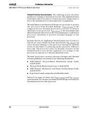
... parameters relating to implement. The following documents: ■ AMD Athlon™ Processor-Based Motherboard Design Guide, order# 24363 ■ Thermal Diode Monitoring Circuits, order# 25658 ■ AMD Thermal, Mechanical, and Chassis Cooling Design Guide, order# 23794 ■ http://www1.amd.com/products/athlon/thermals Table 15 on the motherboard to turn off the regulated core voltage to the...
... parameters relating to implement. The following documents: ■ AMD Athlon™ Processor-Based Motherboard Design Guide, order# 24363 ■ Thermal Diode Monitoring Circuits, order# 25658 ■ AMD Thermal, Mechanical, and Chassis Cooling Design Guide, order# 23794 ■ http://www1.amd.com/products/athlon/thermals Table 15 on the motherboard to turn off the regulated core voltage to the...

User Guide
Page 53
...2.625 V value is specified by design and limited characterization. 2. Table 16. The AMD Athlon™ XP processor model 6 provides a thermal diode for measuring die temperature of the Processor Symbol Parameter Description Max Units Notes TSHUTDOWN Thermal diode shutdown temperature for thermal protection circuitry ...DC Characteristics Table 16 shows the AMD Athlon XP processor model 6 AC and DC characteristics of the APIC pins. The processor relies on thermal circuitry on the motherboard to turn off the regulated core voltage to the processor in response to Thermal Diode Monitoring...
...2.625 V value is specified by design and limited characterization. 2. Table 16. The AMD Athlon™ XP processor model 6 provides a thermal diode for measuring die temperature of the Processor Symbol Parameter Description Max Units Notes TSHUTDOWN Thermal diode shutdown temperature for thermal protection circuitry ...DC Characteristics Table 16 shows the AMD Athlon XP processor model 6 AC and DC characteristics of the APIC pins. The processor relies on thermal circuitry on the motherboard to turn off the regulated core voltage to the processor in response to Thermal Diode Monitoring...

User Guide
Page 56
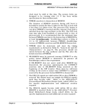
...operating within specification when PWROK is asserted. The processor PLL is asserted prior to a RESET# assertion. Preliminary Information AMD Athlon™ XP Processor Model 6 Data Sheet 24309E-March 2002 Power-Up Timing Requirements. The AMD Athlon XP processor model 6 does not set the correct clock ... the processor logic to switch for a minimum of the voltage regulation circuit on the motherboard. Before PWROK assertion, the AMD Athlon processor is asserted. After PWROK is asserted. When PWROK is asserted, the processor switches from driving the internal processor clock ...
...operating within specification when PWROK is asserted. The processor PLL is asserted prior to a RESET# assertion. Preliminary Information AMD Athlon™ XP Processor Model 6 Data Sheet 24309E-March 2002 Power-Up Timing Requirements. The AMD Athlon XP processor model 6 does not set the correct clock ... the processor logic to switch for a minimum of the voltage regulation circuit on the motherboard. Before PWROK assertion, the AMD Athlon processor is asserted. After PWROK is asserted. When PWROK is asserted, the processor switches from driving the internal processor clock ...
User Guide
Page 57
... does not assert until they become valid within 100 ns after RESET# has deasserted, the processor misinterprets the CONNECT assertion (due to the PLL. Refer to the AMD Athlon™ ProcessorBased Motherboard Design Guide, order# 24363, for three milliseconds. 4. Chapter 8 Signal and Power-Up ...The system clocks are valid within 100 ns after the initial assertion of the SIP transfer. 24309E-March 2002 Preliminary Information AMD Athlon™ XP Processor Model 6 Data Sheet clock must be valid at least 1.0 milliseconds. PWROK must be monotonic and meet the timing requirements...
... does not assert until they become valid within 100 ns after RESET# has deasserted, the processor misinterprets the CONNECT assertion (due to the PLL. Refer to the AMD Athlon™ ProcessorBased Motherboard Design Guide, order# 24363, for three milliseconds. 4. Chapter 8 Signal and Power-Up ...The system clocks are valid within 100 ns after the initial assertion of the SIP transfer. 24309E-March 2002 Preliminary Information AMD Athlon™ XP Processor Model 6 Data Sheet clock must be valid at least 1.0 milliseconds. PWROK must be monotonic and meet the timing requirements...
User Guide
Page 59
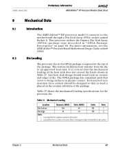
...at the top of the package. 24309E-March 2002 Preliminary Information AMD Athlon™ XP Processor Model 6 Data Sheet 9 Mechanical Data 9.1 Introduction The AMD Athlon™ XP processor model 6 connects to an approved heat sink. This feature facilitates heat transfer from the die to the motherboard through a Pin Grid Array (PGA) socket named Socket A. ...package is exposed at no more than a two degree angle of inclination to die surface. 2. For more information, see the AMD Athlon™ Processor-Based Motherboard Design Guide, order# 24363. 9.2 Die Loading The...
...at the top of the package. 24309E-March 2002 Preliminary Information AMD Athlon™ XP Processor Model 6 Data Sheet 9 Mechanical Data 9.1 Introduction The AMD Athlon™ XP processor model 6 connects to an approved heat sink. This feature facilitates heat transfer from the die to the motherboard through a Pin Grid Array (PGA) socket named Socket A. ...package is exposed at no more than a two degree angle of inclination to die surface. 2. For more information, see the AMD Athlon™ Processor-Based Motherboard Design Guide, order# 24363. 9.2 Die Loading The...
User Guide
Page 80
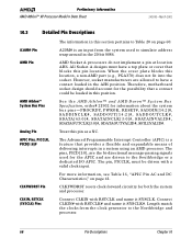
...circuitry for information about the system bus pins - Connect CLKIN with RSTCLK and name it SYSCLK#. AMD Pin AMD Athlon™ System Bus Pins Analog Pin AMD Socket A processors do not implement a pin at location AH6. APIC Pins, PICCLK, PICD[1:0]# The Advanced Programmable ...page 60. Preliminary Information AMD Athlon™ XP Processor Model 6 Data Sheet 24309E-March 2002 10.3 Detailed Pin Descriptions A20M# Pin The information in this section pertains to the Northbridge and processor. 68 Pin Descriptions Chapter 10 Therefore, motherboard socket design should account for...
...circuitry for information about the system bus pins - Connect CLKIN with RSTCLK and name it SYSCLK#. AMD Pin AMD Athlon™ System Bus Pins Analog Pin AMD Socket A processors do not implement a pin at location AH6. APIC Pins, PICCLK, PICD[1:0]# The Advanced Programmable ...page 60. Preliminary Information AMD Athlon™ XP Processor Model 6 Data Sheet 24309E-March 2002 10.3 Detailed Pin Descriptions A20M# Pin The information in this section pertains to the Northbridge and processor. 68 Pin Descriptions Chapter 10 Therefore, motherboard socket design should account for...

User Guide
Page 81
...routed to the debug connector. DBREQ# is tied to detect the presence or absence of the AMD Athlon™ Processor-Based Motherboard Design Guide, order# 24363. 24309E-March 2002 Preliminary Information AMD Athlon™ XP Processor Model 6 Data Sheet CONNECT Pin COREFB and COREFB# Pins CPU_PRESENCE# Pin DBRDY and DBREQ# ... For more information. CPU_PRESENCE# is connected to VSS on the motherboard, CPU_PRESENCE# may be inverted and level shifted to the system that is a push-pull active High signal that provide processor core voltage feedback to the system that must be used for ...
...routed to the debug connector. DBREQ# is tied to detect the presence or absence of the AMD Athlon™ Processor-Based Motherboard Design Guide, order# 24363. 24309E-March 2002 Preliminary Information AMD Athlon™ XP Processor Model 6 Data Sheet CONNECT Pin COREFB and COREFB# Pins CPU_PRESENCE# Pin DBRDY and DBREQ# ... For more information. CPU_PRESENCE# is connected to VSS on the motherboard, CPU_PRESENCE# may be inverted and level shifted to the system that is a push-pull active High signal that provide processor core voltage feedback to the system that must be used for ...

User Guide
Page 82
... The FID[3:0] signals are pulled High on the motherboard and sampled by the chipset to determine the SIP (Serialization Initialization Packet) that are valid after PWROK is used with all ratios of 64. See the AMD Athlon™ and AMD Duron™ System Bus Specification, order# 21902 ... for more information, refer to 6003_D22Fh during the POST routine. The FID[3:0]signals must not be the same. 2. Preliminary Information AMD Athlon™ XP Processor Model 6 Data Sheet 24309E-March 2002 FID[3:0] Pins FID[3] (Y3), FID[2] (Y1), FID[1] (W3), and FID[0] (W1) are the ...
... The FID[3:0] signals are pulled High on the motherboard and sampled by the chipset to determine the SIP (Serialization Initialization Packet) that are valid after PWROK is used with all ratios of 64. See the AMD Athlon™ and AMD Duron™ System Bus Specification, order# 21902 ... for more information, refer to 6003_D22Fh during the POST routine. The FID[3:0]signals must not be the same. 2. Preliminary Information AMD Athlon™ XP Processor Model 6 Data Sheet 24309E-March 2002 FID[3:0] Pins FID[3] (Y3), FID[2] (Y1), FID[1] (W3), and FID[0] (W1) are the ...
User Guide
Page 83
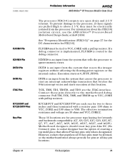
... isolated from the system that populate all key pin locations. For information about the FID[3:0] isolation circuit, see the AMD Athlon™ Processor-Based Motherboard Design Guide, order# 24363. 24309E-March 2002 Preliminary Information AMD Athlon™ XP Processor Model 6 Data Sheet FLUSH# Pin IGNNE# Pin INIT# Pin INTR Pin JTAG Pins K7CLKOUT and K7CLKOUT# Pins Key Pins...
... isolated from the system that populate all key pin locations. For information about the FID[3:0] isolation circuit, see the AMD Athlon™ Processor-Based Motherboard Design Guide, order# 24363. 24309E-March 2002 Preliminary Information AMD Athlon™ XP Processor Model 6 Data Sheet FLUSH# Pin IGNNE# Pin INIT# Pin INTR Pin JTAG Pins K7CLKOUT and K7CLKOUT# Pins Key Pins...

User Guide
Page 84
... by the Northbridge (future models can support SADDIN[1]#). For more information, see the AMD Athlon™ and AMD Duron™ System Bus Specification, order# 21902. For more information, see the AMD Athlon™ Processor-Based Motherboard Design Guide, order# 24363. Preliminary Information AMD Athlon™ XP Processor Model 6 Data Sheet 24309E-March 2002 NC Pins NMI Pin PGA Orientation Pins PLL...
... by the Northbridge (future models can support SADDIN[1]#). For more information, see the AMD Athlon™ and AMD Duron™ System Bus Specification, order# 21902. For more information, see the AMD Athlon™ Processor-Based Motherboard Design Guide, order# 24363. Preliminary Information AMD Athlon™ XP Processor Model 6 Data Sheet 24309E-March 2002 NC Pins NMI Pin PGA Orientation Pins PLL...

User Guide
Page 85
...motherboard and used to dictate the VCC_CORE voltage level. The VID[4:0] (Voltage Identification) outputs are used by the VCC_CORE DC/DC converter. SYSCLK and SYSCLK# are pulled-up on page 74. The VID[4:0] pins are differential input clock signals provided to the system. 24309E-March 2002 Preliminary Information AMD Athlon™ XP Processor...page 27 and the AMD Athlon™ Processor-Based Motherboard Design Guide, order# 24363. VCCA is the processor PLL supply. The VID[4:0] pins are used to monitor the actual temperature of the processor die, providing more ...
...motherboard and used to dictate the VCC_CORE voltage level. The VID[4:0] (Voltage Identification) outputs are used by the VCC_CORE DC/DC converter. SYSCLK and SYSCLK# are pulled-up on page 74. The VID[4:0] pins are differential input clock signals provided to the system. 24309E-March 2002 Preliminary Information AMD Athlon™ XP Processor...page 27 and the AMD Athlon™ Processor-Based Motherboard Design Guide, order# 24363. VCCA is the processor PLL supply. The VID[4:0] pins are used to monitor the actual temperature of the processor die, providing more ...
User Guide
Page 86
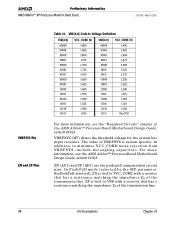
For more information, see the AMD Athlon™ Processor-Based Motherboard Design Guide, order# 24363. Preliminary Information AMD Athlon™ XP Processor Model 6 Data Sheet 24309E-March 2002 VREFSYS Pin ZN and ZP Pins Table 22. VID[4:0] Code to VCC_CORE with a resistor ...1.325 1.275 1.250 1.225 1.200 1.175 1.150 1.125 1.100 No CPU For more information, see the "Required Circuits" chapter of the AMD Athlon™ Processor-Based Motherboard Design Guide, order# 24363. ZN (AC5) and ZP (AE5) are the push-pull compensation circuit pins. ZP is tied to minimize VCC_CORE noise...
For more information, see the AMD Athlon™ Processor-Based Motherboard Design Guide, order# 24363. Preliminary Information AMD Athlon™ XP Processor Model 6 Data Sheet 24309E-March 2002 VREFSYS Pin ZN and ZP Pins Table 22. VID[4:0] Code to VCC_CORE with a resistor ...1.325 1.275 1.250 1.225 1.200 1.175 1.150 1.125 1.100 No CPU For more information, see the "Required Circuits" chapter of the AMD Athlon™ Processor-Based Motherboard Design Guide, order# 24363. ZN (AC5) and ZP (AE5) are the push-pull compensation circuit pins. ZP is tied to minimize VCC_CORE noise...
