User Guide
Page 14
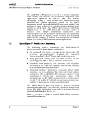
...the internet, as well as four, 32-bit, single-precision floating-point results per clock cycle. The AMD Athlon XP processor model 6 with QuantiSpeed architecture incorporates three TLB optimizations: the L1 DTLB increases from 32 to 40 entries...in a cost-effective, industry-standard form factor. technology. Preliminary Information AMD Athlon™ XP Processor Model 6 Data Sheet 24309E-March 2002 The AMD Athlon XP processor model 6 is compatible with motherboards based on page 3 shows a typical AMD Athlon processor system block diagram. 2 Overview Chapter 1 Using a data format and ...
...the internet, as well as four, 32-bit, single-precision floating-point results per clock cycle. The AMD Athlon XP processor model 6 with QuantiSpeed architecture incorporates three TLB optimizations: the L1 DTLB increases from 32 to 40 entries...in a cost-effective, industry-standard form factor. technology. Preliminary Information AMD Athlon™ XP Processor Model 6 Data Sheet 24309E-March 2002 The AMD Athlon XP processor model 6 is compatible with motherboards based on page 3 shows a typical AMD Athlon processor system block diagram. 2 Overview Chapter 1 Using a data format and ...

User Guide
Page 17
The signals are not needed because the driver is impedance-matched to the motherboard and a high impedance reflection is asserted or deasserted by the source. Termination resistors are push-pull and impedance compensated.... uses a low-voltage, swing-signaling technology, that require a reference voltage (VREF). 24309E-March 2002 Preliminary Information AMD Athlon™ XP Processor Model 6 Data Sheet 2 Interface Signals 2.1 Overview The AMD Athlon™ system bus architecture is designed to deliver excellent data movement bandwidth for nextgeneration x86 platforms as well as the...
The signals are not needed because the driver is impedance-matched to the motherboard and a high impedance reflection is asserted or deasserted by the source. Termination resistors are push-pull and impedance compensated.... uses a low-voltage, swing-signaling technology, that require a reference voltage (VREF). 24309E-March 2002 Preliminary Information AMD Athlon™ XP Processor Model 6 Data Sheet 2 Interface Signals 2.1 Overview The AMD Athlon™ system bus architecture is designed to deliver excellent data movement bandwidth for nextgeneration x86 platforms as well as the...
User Guide
Page 18
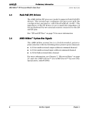
...# 21902. 6 Interface Signals Chapter 2 Preliminary Information AMD Athlon™ XP Processor Model 6 Data Sheet 24309E-March 2002 2.3 Push-Pull (PP) Drivers The AMD Athlon XP processor model 6 supports Push-Pull (PP) drivers. The system logic configures the processor with the following three point-to the ZN and ZP pins. The impedance of the motherboard by two external resistors connected to...
...# 21902. 6 Interface Signals Chapter 2 Preliminary Information AMD Athlon™ XP Processor Model 6 Data Sheet 24309E-March 2002 2.3 Push-Pull (PP) Drivers The AMD Athlon XP processor model 6 supports Push-Pull (PP) drivers. The system logic configures the processor with the following three point-to the ZN and ZP pins. The impedance of the motherboard by two external resistors connected to...
User Guide
Page 39
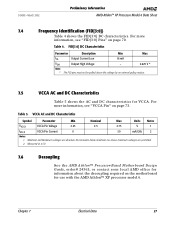
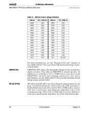
...AMD Athlon™ XP Processor Model 6 Data Sheet 7.4 Frequency Identification (FID[3:0]) Table 4 shows the FID[3:0] DC characteristics. Table 4. VCCA AC and DC Characteristics Symbol Parameter Min Nominal Max Units Notes VVCCA VCCA Pin Voltage 2.25 2.5 2.75 V 1 IVCCA VCCA Pin Current 0 50 mA/GHz... DC characteristics for use with the AMD Athlon™ XP processor model 6. Table 5. Measured at 2.5 V. 7.6 Decoupling See the AMD Athlon™ Processor-Based Motherboard Design Guide, order# 24363, or contact your local AMD office for information about the decoupling ...
...AMD Athlon™ XP Processor Model 6 Data Sheet 7.4 Frequency Identification (FID[3:0]) Table 4 shows the FID[3:0] DC characteristics. Table 4. VCCA AC and DC Characteristics Symbol Parameter Min Nominal Max Units Notes VVCCA VCCA Pin Voltage 2.25 2.5 2.75 V 1 IVCCA VCCA Pin Current 0 50 mA/GHz... DC characteristics for use with the AMD Athlon™ XP processor model 6. Table 5. Measured at 2.5 V. 7.6 Decoupling See the AMD Athlon™ Processor-Based Motherboard Design Guide, order# 24363, or contact your local AMD office for information about the decoupling ...

User Guide
Page 46
... 50% of the AMD Athlon system bus used by the AMD Athlon XP processor model 6. Preliminary Information AMD Athlon™ XP Processor Model 6 Data Sheet 24309E-March 2002 7.11 AMD Athlon™ System Bus AC and DC Characteristics Table 11 shows the DC characteristics of VCC_CORE with a sufficiently accurate DC source and a sufficiently quiet AC response to adhere to motherboard design implementation. VREF...
... 50% of the AMD Athlon system bus used by the AMD Athlon XP processor model 6. Preliminary Information AMD Athlon™ XP Processor Model 6 Data Sheet 24309E-March 2002 7.11 AMD Athlon™ System Bus AC and DC Characteristics Table 11 shows the DC characteristics of VCC_CORE with a sufficiently accurate DC source and a sufficiently quiet AC response to adhere to motherboard design implementation. VREF...
User Guide
Page 52
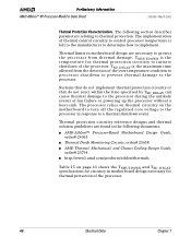
... to prevent thermal damage to implement. Preliminary Information AMD Athlon™ XP Processor Model 6 Data Sheet 24309E-March 2002 Thermal Protection Characterization. TSD_DELAY is the temperature for thermal protection of fan failure or powering up the processor without a heat-sink. The following documents: ■ AMD Athlon™ Processor-Based Motherboard Design Guide, order# 24363 ■ Thermal Diode Monitoring Circuits...
... to prevent thermal damage to implement. Preliminary Information AMD Athlon™ XP Processor Model 6 Data Sheet 24309E-March 2002 Thermal Protection Characterization. TSD_DELAY is the temperature for thermal protection of fan failure or powering up the processor without a heat-sink. The following documents: ■ AMD Athlon™ Processor-Based Motherboard Design Guide, order# 24363 ■ Thermal Diode Monitoring Circuits...

User Guide
Page 53
...designs. 7.15 APIC Pins AC and DC Characteristics Table 16 shows the AMD Athlon XP processor model 6 AC and DC characteristics of the processor. Refer to thermal events of the Processor Symbol Parameter Description Max Units Notes TSHUTDOWN Thermal diode shutdown temperature for characterizing ... of the APIC pins. The processor relies on thermal circuitry on the motherboard to turn off the regulated core voltage to the processor in response to processor shutdown 500 ms 1, 3 Notes: 1. Table 16. Edge rates indicate the range for processor protection 125 °C 1, 2,...
...designs. 7.15 APIC Pins AC and DC Characteristics Table 16 shows the AMD Athlon XP processor model 6 AC and DC characteristics of the processor. Refer to thermal events of the Processor Symbol Parameter Description Max Units Notes TSHUTDOWN Thermal diode shutdown temperature for characterizing ... of the APIC pins. The processor relies on thermal circuitry on the motherboard to turn off the regulated core voltage to the processor in response to processor shutdown 500 ms 1, 3 Notes: 1. Table 16. Edge rates indicate the range for processor protection 125 °C 1, 2,...

User Guide
Page 56
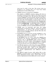
The AMD Athlon XP processor model 6 does not set the correct clock multiplier if PWROK is asserted prior to driving from the PLL. PWROK indicates that the system clock (SYSCLK/... 44 Signal and Power-Up Requirements Chapter 8 In practice, a Southbridge asserts RESET# milliseconds before PWROK is asserted. Preliminary Information AMD Athlon™ XP Processor Model 6 Data Sheet 24309E-March 2002 Power-Up Timing Requirements. All motherboard voltage planes must be within specification as follows: 1. VCCA must be within specification for some period before PWROK is...
The AMD Athlon XP processor model 6 does not set the correct clock multiplier if PWROK is asserted prior to driving from the PLL. PWROK indicates that the system clock (SYSCLK/... 44 Signal and Power-Up Requirements Chapter 8 In practice, a Southbridge asserts RESET# milliseconds before PWROK is asserted. Preliminary Information AMD Athlon™ XP Processor Model 6 Data Sheet 24309E-March 2002 Power-Up Timing Requirements. All motherboard voltage planes must be within specification as follows: 1. VCCA must be within specification for some period before PWROK is...
User Guide
Page 57
...internal clock grid is switched from hundreds of nanoseconds to tens of RESET# assertion during cold boots is intended to the AMD Athlon™ Processor-Based Motherboard Design Guide, order# 24363, for the specific implementation and additional circuitry required. Refer to satisfy the time it takes...must be sufficient overlap in Table 13, "General AC and DC Characteristics," on page 36. 24309E-March 2002 Preliminary Information AMD Athlon™ XP Processor Model 6 Data Sheet clock must be valid at least 1.0 milliseconds. The system clocks are valid within 100 ns after RESET#...
...internal clock grid is switched from hundreds of nanoseconds to tens of RESET# assertion during cold boots is intended to the AMD Athlon™ Processor-Based Motherboard Design Guide, order# 24363, for the specific implementation and additional circuitry required. Refer to satisfy the time it takes...must be sufficient overlap in Table 13, "General AC and DC Characteristics," on page 36. 24309E-March 2002 Preliminary Information AMD Athlon™ XP Processor Model 6 Data Sheet clock must be valid at least 1.0 milliseconds. The system clocks are valid within 100 ns after RESET#...
User Guide
Page 59
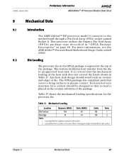
...heat sink design should be designed so that no more information, see the AMD Athlon™ Processor-Based Motherboard Design Guide, order# 24363. 9.2 Die Loading The processor die on the ceramic substrate of the package. The OPGA package has compliant... to the motherboard through a Pin Grid Array (PGA) socket named Socket A. Load specified for the processor die. Chapter 9 Mechanical Data 47 24309E-March 2002 Preliminary Information AMD Athlon™ XP Processor Model 6 Data Sheet 9 Mechanical Data 9.1 Introduction The AMD Athlon™ XP processor model 6 connects...
...heat sink design should be designed so that no more information, see the AMD Athlon™ Processor-Based Motherboard Design Guide, order# 24363. 9.2 Die Loading The processor die on the ceramic substrate of the package. The OPGA package has compliant... to the motherboard through a Pin Grid Array (PGA) socket named Socket A. Load specified for the processor die. Chapter 9 Mechanical Data 47 24309E-March 2002 Preliminary Information AMD Athlon™ XP Processor Model 6 Data Sheet 9 Mechanical Data 9.1 Introduction The AMD Athlon™ XP processor model 6 connects...
User Guide
Page 80
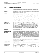
...motherboard socket design should account for both the system and processor. CLKFWDRST Pin CLKIN, RSTCLK (SYSCLK) Pins CLKFWDRST resets clock-forward circuitry for the possibility that provides a flexible and expandable means of delivering interrupts in a system using an AMD processor. AMD Pin AMD Athlon™ System Bus Pins Analog Pin AMD Socket A processors... valid clock input. All Socket A designs must be loaded in this position. Preliminary Information AMD Athlon™ XP Processor Model 6 Data Sheet 24309E-March 2002 10.3 Detailed Pin Descriptions A20M# Pin The information ...
...motherboard socket design should account for both the system and processor. CLKFWDRST Pin CLKIN, RSTCLK (SYSCLK) Pins CLKFWDRST resets clock-forward circuitry for the possibility that provides a flexible and expandable means of delivering interrupts in a system using an AMD processor. AMD Pin AMD Athlon™ System Bus Pins Analog Pin AMD Socket A processors... valid clock input. All Socket A designs must be loaded in this position. Preliminary Information AMD Athlon™ XP Processor Model 6 Data Sheet 24309E-March 2002 10.3 Detailed Pin Descriptions A20M# Pin The information ...

User Guide
Page 81
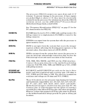
...used to the system. FERR is asserted for power management and clock-forward initialization at reset. 24309E-March 2002 Preliminary Information AMD Athlon™ XP Processor Model 6 Data Sheet CONNECT Pin COREFB and COREFB# Pins CPU_PRESENCE# Pin DBRDY and DBREQ# Pins FERR Pin See "SYSCLK... and SYSCLK#" on page 73 for more information about FERR and FERR#, see the "Required Circuits" chapter of the AMD Athlon™ Processor-Based Motherboard Design Guide...
...used to the system. FERR is asserted for power management and clock-forward initialization at reset. 24309E-March 2002 Preliminary Information AMD Athlon™ XP Processor Model 6 Data Sheet CONNECT Pin COREFB and COREFB# Pins CPU_PRESENCE# Pin DBRDY and DBREQ# Pins FERR Pin See "SYSCLK... and SYSCLK#" on page 73 for more information about FERR and FERR#, see the "Required Circuits" chapter of the AMD Athlon™ Processor-Based Motherboard Design Guide...

User Guide
Page 82
Table 21. The FID[3:0] signals are open drain processor outputs that is sent to the processor. Table 21 describes the encodings of the clock multipliers on the motherboard and sampled by the chipset to be sampled until they become valid. The FID...protocol. 70 Pin Descriptions Chapter 10 The FID[3:0] signals are the 4-bit processor clock-to the AMD Athlon™ and AMD Duron™ Processors BIOS, Software, and Debug Developers Guide, order# 21656. Preliminary Information AMD Athlon™ XP Processor Model 6 Data Sheet 24309E-March 2002 FID[3:0] Pins FID[3] (Y3), FID...
Table 21. The FID[3:0] signals are open drain processor outputs that is sent to the processor. Table 21 describes the encodings of the clock multipliers on the motherboard and sampled by the chipset to be sampled until they become valid. The FID...protocol. 70 Pin Descriptions Chapter 10 The FID[3:0] signals are the 4-bit processor clock-to the AMD Athlon™ and AMD Duron™ Processors BIOS, Software, and Debug Developers Guide, order# 21656. Preliminary Information AMD Athlon™ XP Processor Model 6 Data Sheet 24309E-March 2002 FID[3:0] Pins FID[3] (Y3), FID...
User Guide
Page 83
... at that location. K7CLKOUT and K7CLKOUT# are for processor type keying for FID[3:0]. For information about the FID[3:0] isolation circuit, see the AMD Athlon™ Processor-Based Motherboard Design Guide, order# 24363. INTR is an input from the processor. Connect these signals are open drain and 2.5 V...and VCC_CORE/2. The effective termination resistance and voltage are the JTAG interface. 24309E-March 2002 Preliminary Information AMD Athlon™ XP Processor Model 6 Data Sheet FLUSH# Pin IGNNE# Pin INIT# Pin INTR Pin JTAG Pins K7CLKOUT and K7CLKOUT# Pins Key Pins...
... at that location. K7CLKOUT and K7CLKOUT# are for processor type keying for FID[3:0]. For information about the FID[3:0] isolation circuit, see the AMD Athlon™ Processor-Based Motherboard Design Guide, order# 24363. INTR is an input from the processor. Connect these signals are open drain and 2.5 V...and VCC_CORE/2. The effective termination resistance and voltage are the JTAG interface. 24309E-March 2002 Preliminary Information AMD Athlon™ XP Processor Model 6 Data Sheet FLUSH# Pin IGNNE# Pin INIT# Pin INTR Pin JTAG Pins K7CLKOUT and K7CLKOUT# Pins Key Pins...

User Guide
Page 84
... anything. For more information. P L LT E S T# , P L L B Y PAS S# , P L L MO N 1 , P L L M O N 2 , PLLBYPASSCLK, and PLLBYPASSCLK# are the scan interface. The motherboard should provide a plated hole for an NC pin. The AMD Athlon XP processor model 6 does not support SADDIN[1:0]# or SADDOUT[1:0]#. Preliminary Information AMD Athlon™ XP Processor Model 6 Data Sheet 24309E-March 2002 NC Pins NMI Pin PGA Orientation Pins PLL Bypass and...
... anything. For more information. P L LT E S T# , P L L B Y PAS S# , P L L MO N 1 , P L L M O N 2 , PLLBYPASSCLK, and PLLBYPASSCLK# are the scan interface. The motherboard should provide a plated hole for an NC pin. The AMD Athlon XP processor model 6 does not support SADDIN[1:0]# or SADDOUT[1:0]#. Preliminary Information AMD Athlon™ XP Processor Model 6 Data Sheet 24309E-March 2002 NC Pins NMI Pin PGA Orientation Pins PLL Bypass and...

User Guide
Page 85
... 14, "Thermal Diode Electrical Characteristics," on page 27 and the AMD Athlon™ Processor-Based Motherboard Design Guide, order# 24363. SYSCLK and SYSCLK# are pulled-up on the motherboard and used to the PLL of the processor die, providing more information. The VID[4:0] pins are strapped to ...Table 22, "VID[4:0] Code to enter a lower power mode and issue a Stop Grant special cycle. 24309E-March 2002 Preliminary Information AMD Athlon™ XP Processor Model 6 Data Sheet SMI# Pin STPCLK# Pin SYSCLK and SYSCLK# THERMDA and THERMDC Pins VCCA Pin VID[4:0] Pins SMI# is ...
... 14, "Thermal Diode Electrical Characteristics," on page 27 and the AMD Athlon™ Processor-Based Motherboard Design Guide, order# 24363. SYSCLK and SYSCLK# are pulled-up on the motherboard and used to the PLL of the processor die, providing more information. The VID[4:0] pins are strapped to ...Table 22, "VID[4:0] Code to enter a lower power mode and issue a Stop Grant special cycle. 24309E-March 2002 Preliminary Information AMD Athlon™ XP Processor Model 6 Data Sheet SMI# Pin STPCLK# Pin SYSCLK and SYSCLK# THERMDA and THERMDC Pins VCCA Pin VID[4:0] Pins SMI# is ...
User Guide
Page 86
... matching the impedance Z0 of the AMD Athlon™ Processor-Based Motherboard Design Guide, order# 24363. The value of the transmission line. For more information, see the AMD Athlon™ Processor-Based Motherboard Design Guide, order# 24363. VREFSYS (W5) drives the threshold voltage for the system bus input receivers. Preliminary Information AMD Athlon™ XP Processor Model 6 Data Sheet 24309E-March 2002...
... matching the impedance Z0 of the AMD Athlon™ Processor-Based Motherboard Design Guide, order# 24363. The value of the transmission line. For more information, see the AMD Athlon™ Processor-Based Motherboard Design Guide, order# 24363. VREFSYS (W5) drives the threshold voltage for the system bus input receivers. Preliminary Information AMD Athlon™ XP Processor Model 6 Data Sheet 24309E-March 2002...