
Data Sheet
Page 15
.... Typical AMD Athlon™ XP Processor Model 10 System Block Diagram Chapter 1 Overview 3 AMD Athlon™ XP Processor Model 10 AMD Athlon System Bus System Controller (Northbridge) AGP Bus Memory Bus PCI Bus AGP SDRAM or DDR Peripheral Bus Controller (Southbridge) LAN SCSI Modem / Audio LPC Bus USB Dual EIDE BIOS Figure 1. The AMD Athlon XP processor model 10 is compatible with motherboards based on...
.... Typical AMD Athlon™ XP Processor Model 10 System Block Diagram Chapter 1 Overview 3 AMD Athlon™ XP Processor Model 10 AMD Athlon System Bus System Controller (Northbridge) AGP Bus Memory Bus PCI Bus AGP SDRAM or DDR Peripheral Bus Controller (Southbridge) LAN SCSI Modem / Audio LPC Bus USB Dual EIDE BIOS Figure 1. The AMD Athlon XP processor model 10 is compatible with motherboards based on...

Data Sheet
Page 17
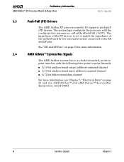
...Socket A socket. Chapter 2 Interface Signals 5 The signals are not needed because the driver is impedance-matched to the motherboard and a high impedance reflection is asserted or deasserted by the source. Termination resistors are push-pull and impedance compensated....class application software. 26237C-May 2003 Preliminary Information AMD Athlon™ XP Processor Model 10 Data Sheet 2 Interface Signals This section describes the interface signals utilized by the AMD Athlon™ XP processor model 10. 2.1 Overview The AMD Athlon™ system bus architecture is designed to ...
...Socket A socket. Chapter 2 Interface Signals 5 The signals are not needed because the driver is impedance-matched to the motherboard and a high impedance reflection is asserted or deasserted by the source. Termination resistors are push-pull and impedance compensated....class application software. 26237C-May 2003 Preliminary Information AMD Athlon™ XP Processor Model 10 Data Sheet 2 Interface Signals This section describes the interface signals utilized by the AMD Athlon™ XP processor model 10. 2.1 Overview The AMD Athlon™ system bus architecture is designed to ...
Data Sheet
Page 18
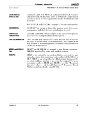
... channel For more information. 2.4 AMD Athlon™ System Bus Signals The AMD Athlon system bus is set to match the impedance of the motherboard by two external resistors connected to the ZN and ZP pins. Preliminary Information AMD Athlon™ XP Processor Model 10 Data Sheet 26237C-May 2003 2.3 Push-Pull (PP) Drivers The AMD Athlon XP processor model 10 supports push-pull...
... channel For more information. 2.4 AMD Athlon™ System Bus Signals The AMD Athlon system bus is set to match the impedance of the motherboard by two external resistors connected to the ZN and ZP pins. Preliminary Information AMD Athlon™ XP Processor Model 10 Data Sheet 26237C-May 2003 2.3 Push-Pull (PP) Drivers The AMD Athlon XP processor model 10 supports push-pull...

Data Sheet
Page 36
... 4. VREF is nominally set to 50% of the AMD Athlon system bus for this processor. VREF must be created with actual values that are specific to motherboard design implementation. Advanced 333 FSB AMD Athlon™ System Bus DC Characteristics Symbol Parameter Condition Min Max...Measured at VCC_CORE / 2. 24 Advanced 333 Front-Side Bus AMD Athlon™ XP Processor Model 10 Specifications Chapter 6 Preliminary Information AMD Athlon™ XP Processor Model 10 Data Sheet 26237C-May 2003 6.4 Advanced 333 FSB AMD Athlon™ System Bus DC Characteristics Table 4 shows the DC...
... 4. VREF is nominally set to 50% of the AMD Athlon system bus for this processor. VREF must be created with actual values that are specific to motherboard design implementation. Advanced 333 FSB AMD Athlon™ System Bus DC Characteristics Symbol Parameter Condition Min Max...Measured at VCC_CORE / 2. 24 Advanced 333 Front-Side Bus AMD Athlon™ XP Processor Model 10 Specifications Chapter 6 Preliminary Information AMD Athlon™ XP Processor Model 10 Data Sheet 26237C-May 2003 6.4 Advanced 333 FSB AMD Athlon™ System Bus DC Characteristics Table 4 shows the DC...

Data Sheet
Page 40
...RsetN Impedance Set Point, N Channel 40 70 Ω2 Notes: 1. Preliminary Information AMD Athlon™ XP Processor Model 10 Data Sheet 26237C-May 2003 7.4 Advanced 400 FSB AMD Athlon™ System Bus DC Characteristics Table 8 shows the DC characteristics of VCC_CORE with... a sufficiently accurate DC source and a sufficiently quiet AC response to adhere to the ± 50 mV specification listed above. 2. VREF must be created with actual values that are specific to motherboard...
...RsetN Impedance Set Point, N Channel 40 70 Ω2 Notes: 1. Preliminary Information AMD Athlon™ XP Processor Model 10 Data Sheet 26237C-May 2003 7.4 Advanced 400 FSB AMD Athlon™ System Bus DC Characteristics Table 8 shows the DC characteristics of VCC_CORE with... a sufficiently accurate DC source and a sufficiently quiet AC response to adhere to the ± 50 mV specification listed above. 2. VREF must be created with actual values that are specific to motherboard...

Data Sheet
Page 43
... DC Characteristics Table 12 shows the AC and DC characteristics for use with the AMD Athlon XP processor model 10. VCC_CORE | ≤ 1.60 V V 1 - 2 IVCCA VCCA Pin Current 0 50 mA/GHz 3 Notes: 1. Measured at 2.5 V. 8.6 Decoupling See the AMD Athlon™ Processor-Based Motherboard Design Guide, order# 24363, or contact your local AMD office for information about the decoupling required on the...
... DC Characteristics Table 12 shows the AC and DC characteristics for use with the AMD Athlon XP processor model 10. VCC_CORE | ≤ 1.60 V V 1 - 2 IVCCA VCCA Pin Current 0 50 mA/GHz 3 Notes: 1. Measured at 2.5 V. 8.6 Decoupling See the AMD Athlon™ Processor-Based Motherboard Design Guide, order# 24363, or contact your local AMD office for information about the decoupling required on the...

Data Sheet
Page 52
... TSHUTDOWN and TSD_DELAY specifications for circuitry in motherboard design necessary for thermal protection circuitry to the processor. Preliminary Information AMD Athlon™ XP Processor Model 10 Data Sheet 26237C-May 2003 Thermal limits in motherboard design are found in the following documents: ■ AMD Athlon™ Processor-Based Motherboard Design Guide, order# 24363 ■ AMD Thermal, Mechanical, and Chassis Cooling Design Guide...
... TSHUTDOWN and TSD_DELAY specifications for circuitry in motherboard design necessary for thermal protection circuitry to the processor. Preliminary Information AMD Athlon™ XP Processor Model 10 Data Sheet 26237C-May 2003 Thermal limits in motherboard design are found in the following documents: ■ AMD Athlon™ Processor-Based Motherboard Design Guide, order# 24363 ■ AMD Thermal, Mechanical, and Chassis Cooling Design Guide...

Data Sheet
Page 53
Refer to 2.5 V plus a maximum of the AMD Athlon™ ProcessorBased Motherboard Design Guide, order# 24363. 4. VCC_CORE | ≤ 1.60 V V 3 VOL Output Low Voltage -300 400 mV ILEAK_P Tristate Leakage Pullup VIN = VSS (...Generation Circuit" found in the section, "Motherboard Required Circuits," of five percent. 3. Characterized across DC supply voltage range. 2. 26237C-May 2003 Preliminary Information AMD Athlon™ XP Processor Model 10 Data Sheet 8.13 APIC Pins AC and DC Characteristics Table 19 shows the AMD Athlon XP processor model 10 AC and DC characteristics of...
Refer to 2.5 V plus a maximum of the AMD Athlon™ ProcessorBased Motherboard Design Guide, order# 24363. 4. VCC_CORE | ≤ 1.60 V V 3 VOL Output Low Voltage -300 400 mV ILEAK_P Tristate Leakage Pullup VIN = VSS (...Generation Circuit" found in the section, "Motherboard Required Circuits," of five percent. 3. Characterized across DC supply voltage range. 2. 26237C-May 2003 Preliminary Information AMD Athlon™ XP Processor Model 10 Data Sheet 8.13 APIC Pins AC and DC Characteristics Table 19 shows the AMD Athlon XP processor model 10 AC and DC characteristics of...

Data Sheet
Page 56
... all other voltage planes must be within specification for some period before PWROK is an output of the voltage regulation circuit on the motherboard. The reference system 44 Signal and Power-Up Requirements Chapter 9 The AMD Athlon XP processor model 10 does not set the correct clock multiplier if PWROK is powered by VCCA. The...
... all other voltage planes must be within specification for some period before PWROK is an output of the voltage regulation circuit on the motherboard. The reference system 44 Signal and Power-Up Requirements Chapter 9 The AMD Athlon XP processor model 10 does not set the correct clock multiplier if PWROK is powered by VCCA. The...

Data Sheet
Page 57
...time between PWROK assertion to also assert) before RESET# is asserted. Refer to the AMD Athlon™ Processor-Based Motherboard Design Guide, order# 24363, for the specific implementation and additional circuitry required. If ...NB_RESET# does not assert until they become valid within specification for the PLL to tens of the SIP transfer. The FID[3:0] signals become valid. 26237C-May 2003 Preliminary Information AMD Athlon™ XP Processor...
...time between PWROK assertion to also assert) before RESET# is asserted. Refer to the AMD Athlon™ Processor-Based Motherboard Design Guide, order# 24363, for the specific implementation and additional circuitry required. If ...NB_RESET# does not assert until they become valid within specification for the PLL to tens of the SIP transfer. The FID[3:0] signals become valid. 26237C-May 2003 Preliminary Information AMD Athlon™ XP Processor...

Data Sheet
Page 59
...Array (OPGA) package type described in Table 20. Any heat sink design should be designed so that no more information, see the AMD Athlon™ Processor-Based Motherboard Design Guide, order# 24363. It is placed on corners and edges of the package. Load defined for a surface at the top ... For more than a two-degree angle of the package. Chapter 10 Mechanical Data 47 Table 20. 26237C-May 2003 Preliminary Information AMD Athlon™ XP Processor Model 10 Data Sheet 10 10.1 Mechanical Data The AMD Athlon™ XP processor model 10 connects to die surface.
...Array (OPGA) package type described in Table 20. Any heat sink design should be designed so that no more information, see the AMD Athlon™ Processor-Based Motherboard Design Guide, order# 24363. It is placed on corners and edges of the package. Load defined for a surface at the top ... For more than a two-degree angle of the package. Chapter 10 Mechanical Data 47 Table 20. 26237C-May 2003 Preliminary Information AMD Athlon™ XP Processor Model 10 Data Sheet 10 10.1 Mechanical Data The AMD Athlon™ XP processor model 10 connects to die surface.

Data Sheet
Page 84
... that provides a flexible and expandable means of the AMD Athlon™ Processor Motherboard Design Guide, order# 24363 for information about the system bus pins - Chapter 11 Pin Descriptions 72 26237C-May 2003 Preliminary Information AMD Athlon™ XP Processor Model 10 Data Sheet 11.3 Detailed Pin Descriptions A20M# Pin AMD Pin AMD Athlon™ System Bus Pins Analog Pin APIC Pins...
... that provides a flexible and expandable means of the AMD Athlon™ Processor Motherboard Design Guide, order# 24363 for information about the system bus pins - Chapter 11 Pin Descriptions 72 26237C-May 2003 Preliminary Information AMD Athlon™ XP Processor Model 10 Data Sheet 11.3 Detailed Pin Descriptions A20M# Pin AMD Pin AMD Athlon™ System Bus Pins Analog Pin APIC Pins...
Data Sheet
Page 85
26237C-May 2003 Preliminary Information AMD Athlon™ XP Processor Model 10 Data Sheet CLKIN, RSTCLK (SYSCLK) Pins CONNECT Pin COREFB and COREFB# Pins CPU_PRESENCE# Pin DBRDY and DBREQ# Pins FERR Pin Connect CLKIN with a ... that must be used for power management and clock-forward initialization at reset. CONNECT is tied to detect the presence or absence of the AMD Athlon™ Processor-Based Motherboard Design Guide, order# 24363. DBREQ# is an input from the clock generator to VSS on page 77 for any unmasked numerical exception independent of...
26237C-May 2003 Preliminary Information AMD Athlon™ XP Processor Model 10 Data Sheet CLKIN, RSTCLK (SYSCLK) Pins CONNECT Pin COREFB and COREFB# Pins CPU_PRESENCE# Pin DBRDY and DBREQ# Pins FERR Pin Connect CLKIN with a ... that must be used for power management and clock-forward initialization at reset. CONNECT is tied to detect the presence or absence of the AMD Athlon™ Processor-Based Motherboard Design Guide, order# 24363. DBREQ# is an input from the clock generator to VSS on page 77 for any unmasked numerical exception independent of...

Data Sheet
Page 86
... describes the encodings of the clock multipliers on the motherboard and sampled by the chipset to determine the SIP (serial initialization packet) that is sent to the AMD Athlon™ and AMD Duron™ Processors BIOS, Software, and Debug Developers Guide, order# 21656...10 1111 10.5 Notes: 1. The FID[3:0] signals are open -drain and 2.5-V tolerant. The processor FID[3:0] outputs are open -drain processor outputs that are pulled High on FID[3:0]. Preliminary Information AMD Athlon™ XP Processor Model 10 Data Sheet 26237C-May 2003 FID[3:0] Pins 74 FID[3] (Y3), FID[2] (Y1),...
... describes the encodings of the clock multipliers on the motherboard and sampled by the chipset to determine the SIP (serial initialization packet) that is sent to the AMD Athlon™ and AMD Duron™ Processors BIOS, Software, and Debug Developers Guide, order# 21656...10 1111 10.5 Notes: 1. The FID[3:0] signals are open -drain and 2.5-V tolerant. The processor FID[3:0] outputs are open -drain processor outputs that are pulled High on FID[3:0]. Preliminary Information AMD Athlon™ XP Processor Model 10 Data Sheet 26237C-May 2003 FID[3:0] Pins 74 FID[3] (Y3), FID[2] (Y1),...

Data Sheet
Page 87
... a 1 kΩ resistor. Chapter 11 Pin Descriptions 75 26237C-May 2003 Preliminary Information AMD Athlon™ XP Processor Model 10 Data Sheet FSB_Sense[1:0] Pins FLUSH# Pin IGNNE# Pin INIT# Pin signals High above 2.5 V. Refer to the processor core voltage. See "Frequency Identification (FID[3:0])" on the motherboard. FSB_Sense[1:0] pins are 3.3-V tolerant. Table 26. Front-Side Bus Sense Truth...
... a 1 kΩ resistor. Chapter 11 Pin Descriptions 75 26237C-May 2003 Preliminary Information AMD Athlon™ XP Processor Model 10 Data Sheet FSB_Sense[1:0] Pins FLUSH# Pin IGNNE# Pin INIT# Pin signals High above 2.5 V. Refer to the processor core voltage. See "Frequency Identification (FID[3:0])" on the motherboard. FSB_Sense[1:0] pins are 3.3-V tolerant. Table 26. Front-Side Bus Sense Truth...

Data Sheet
Page 88
... PLLMON1, and PLLMON2) are running within specification and all system clocks are tied to VCC_CORE with pullup resistors. Preliminary Information AMD Athlon™ XP Processor Model 10 Data Sheet 26237C-May 2003 INTR Pin JTAG Pins K7CLKOUT and K7CLKOUT# Pins Key Pins NC Pins NMI Pin PGA... to three inches and then terminated with a resistor pair: 100 ohms to VCC_CORE and 100 ohms to the processor must always provide for more information, see the AMD Athlon™ Processor-Based Motherboard Design Guide, order# 24363. This interface is an input from the system that causes the...
... PLLMON1, and PLLMON2) are running within specification and all system clocks are tied to VCC_CORE with pullup resistors. Preliminary Information AMD Athlon™ XP Processor Model 10 Data Sheet 26237C-May 2003 INTR Pin JTAG Pins K7CLKOUT and K7CLKOUT# Pins Key Pins NC Pins NMI Pin PGA... to three inches and then terminated with a resistor pair: 100 ohms to VCC_CORE and 100 ohms to the processor must always provide for more information, see the AMD Athlon™ Processor-Based Motherboard Design Guide, order# 24363. This interface is an input from the system that causes the...

Data Sheet
Page 89
...pins are pulled up on the processor package. See Table 13, "Thermal Diode Electrical Characteristics," on page 35 and the AMD Athlon™ Processor-Based Motherboard Design Guide, order# 24363. For information about the VCCA pin, see the AMD Athlon™ and AMD Duron™ System Bus Specification,... Pins Scan Pins SMI# Pin STPCLK# Pin SYSCLK and SYSCLK# THERMDA and THERMDC Pins VCCA Pin VID[4:0] Pins The AMD Athlon XP processor model 10 does not support SADDIN[1:0]# or SADDOUT[1:0]#. SCANSHIFTEN, SCANCLK1, SCANINTEVAL, and SCANCLK2 are differential input clock signals provided...
...pins are pulled up on the processor package. See Table 13, "Thermal Diode Electrical Characteristics," on page 35 and the AMD Athlon™ Processor-Based Motherboard Design Guide, order# 24363. For information about the VCCA pin, see the AMD Athlon™ and AMD Duron™ System Bus Specification,... Pins Scan Pins SMI# Pin STPCLK# Pin SYSCLK and SYSCLK# THERMDA and THERMDC Pins VCCA Pin VID[4:0] Pins The AMD Athlon XP processor model 10 does not support SADDIN[1:0]# or SADDOUT[1:0]#. SCANSHIFTEN, SCANCLK1, SCANINTEVAL, and SCANCLK2 are differential input clock signals provided...

Data Sheet
Page 90
.... In addition, to VCC_CORE with a resistor that has a resistance matching the impedance Z0 of the AMD Athlon™ Processor-Based Motherboard Design Guide, order# 24363. For more information, see the AMD Athlon™ Processor-Based Motherboard Design Guide, order# 24363. Preliminary Information AMD Athlon™ XP Processor Model 10 Data Sheet 26237C-May 2003 VREFSYS Pin ZN and ZP Pins The VID...
.... In addition, to VCC_CORE with a resistor that has a resistance matching the impedance Z0 of the AMD Athlon™ Processor-Based Motherboard Design Guide, order# 24363. For more information, see the AMD Athlon™ Processor-Based Motherboard Design Guide, order# 24363. Preliminary Information AMD Athlon™ XP Processor Model 10 Data Sheet 26237C-May 2003 VREFSYS Pin ZN and ZP Pins The VID...