
Data Sheet
Page 13
... and compatible Socket A infrastructure of the AMD Athlon processor. 26237C-May 2003 Preliminary Information AMD Athlon™ XP Processor Model 10 Data Sheet 1 Overview The AMD Athlon™ XP processor model 10 with an integrated, exclusive L2 cache, which supports the growing processor and system bandwidth requirements of emerging software, graphics, I/O, and memory technologies. The high-speed execution core of the AMD Athlon XP processor model 10...
... and compatible Socket A infrastructure of the AMD Athlon processor. 26237C-May 2003 Preliminary Information AMD Athlon™ XP Processor Model 10 Data Sheet 1 Overview The AMD Athlon™ XP processor model 10 with an integrated, exclusive L2 cache, which supports the growing processor and system bandwidth requirements of emerging software, graphics, I/O, and memory technologies. The high-speed execution core of the AMD Athlon XP processor model 10...

Data Sheet
Page 15
... 2003 Thermal Monitor Preliminary Information AMD Athlon™ XP Processor Model 10 Data Sheet The AMD Athlon XP processor model 10 delivers excellent system performance in a cost-effective, industry-standard form factor. Typical AMD Athlon™ XP Processor Model 10 System Block Diagram Chapter 1 Overview 3 The AMD Athlon XP processor model 10 is compatible with motherboards based on Socket A. Figure 1 shows a typical AMD Athlon XP processor model 10 system block diagram...
... 2003 Thermal Monitor Preliminary Information AMD Athlon™ XP Processor Model 10 Data Sheet The AMD Athlon XP processor model 10 delivers excellent system performance in a cost-effective, industry-standard form factor. Typical AMD Athlon™ XP Processor Model 10 System Block Diagram Chapter 1 Overview 3 The AMD Athlon XP processor model 10 is compatible with motherboards based on Socket A. Figure 1 shows a typical AMD Athlon XP processor model 10 system block diagram...

Data Sheet
Page 17
... Socket A socket. Termination resistors are push-pull and impedance compensated. For more information, see Chapter 11, "Pin Descriptions" on page 53, and the AMD Athlon™ and AMD Duron™ System Bus Specification, order# 21902. 2.2 Signaling Technology The AMD Athlon ... signals. 26237C-May 2003 Preliminary Information AMD Athlon™ XP Processor Model 10 Data Sheet 2 Interface Signals This section describes the interface signals utilized by the AMD Athlon™ XP processor model 10. 2.1 Overview The AMD Athlon™ system bus architecture is designed ...
... Socket A socket. Termination resistors are push-pull and impedance compensated. For more information, see Chapter 11, "Pin Descriptions" on page 53, and the AMD Athlon™ and AMD Duron™ System Bus Specification, order# 21902. 2.2 Signaling Technology The AMD Athlon ... signals. 26237C-May 2003 Preliminary Information AMD Athlon™ XP Processor Model 10 Data Sheet 2 Interface Signals This section describes the interface signals utilized by the AMD Athlon™ XP processor model 10. 2.1 Overview The AMD Athlon™ system bus architecture is designed ...

Data Sheet
Page 59
... socket named Socket A. Any heat sink design should be designed so that the mechanical loading of the package. 26237C-May 2003 Preliminary Information AMD Athlon™ XP Processor Model 10 Data Sheet 10 10.1 Mechanical Data The AMD Athlon™ XP processor model 10 connects to die surface. 2. This processor ...Table 20. Load defined for the processor die. Tool-assisted zero insertion force sockets should avoid loads on the OPGA package is exposed at no load is critical that no more information, see the AMD Athlon™ Processor-Based Motherboard Design Guide, order# ...
... socket named Socket A. Any heat sink design should be designed so that the mechanical loading of the package. 26237C-May 2003 Preliminary Information AMD Athlon™ XP Processor Model 10 Data Sheet 10 10.1 Mechanical Data The AMD Athlon™ XP processor model 10 connects to die surface. 2. This processor ...Table 20. Load defined for the processor die. Tool-assisted zero insertion force sockets should avoid loads on the OPGA package is exposed at no load is critical that no more information, see the AMD Athlon™ Processor-Based Motherboard Design Guide, order# ...

Data Sheet
Page 75
... with respect to share the pin. For more information, see "Push-Pull (PP) Drivers" on page 64 cross-references Socket A pin location to signal name. 26237C-May 2003 Preliminary Information AMD Athlon™ XP Processor Model 10 Data Sheet 11.2 Pin List Table 24 on page 6. "O" indicates open-drain mode that allows devices to the...
... with respect to share the pin. For more information, see "Push-Pull (PP) Drivers" on page 64 cross-references Socket A pin location to signal name. 26237C-May 2003 Preliminary Information AMD Athlon™ XP Processor Model 10 Data Sheet 11.2 Pin List Table 24 on page 6. "O" indicates open-drain mode that allows devices to the...

Data Sheet
Page 84
...-forward circuitry for information about the system bus pins - 26237C-May 2003 Preliminary Information AMD Athlon™ XP Processor Model 10 Data Sheet 11.3 Detailed Pin Descriptions A20M# Pin AMD Pin AMD Athlon™ System Bus Pins Analog Pin APIC Pins, PICCLK, PICD[1:0]# CLKFWDRST Pin The ...information in this section pertains to simulate address wrap-around in the 20-bit 8086. All Socket A designs...
...-forward circuitry for information about the system bus pins - 26237C-May 2003 Preliminary Information AMD Athlon™ XP Processor Model 10 Data Sheet 11.3 Detailed Pin Descriptions A20M# Pin AMD Pin AMD Athlon™ System Bus Pins Analog Pin APIC Pins, PICCLK, PICD[1:0]# CLKFWDRST Pin The ...information in this section pertains to simulate address wrap-around in the 20-bit 8086. All Socket A designs...
Data Sheet
Page 85
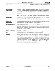
... that must be used for more information about FERR and FERR#, see the "Required Circuits" chapter of the AMD Athlon™ Processor-Based Motherboard Design Guide, order# 24363. Connect CLKIN# with a pullup resistor. If pulled-up on the ...Socket A-style socket. For more information. CPU_PRESENCE# is tied to the Northbridge and processor. Chapter 11 Pin Descriptions 73 Length match the clocks from the system used to VSS on page 77 for power management and clock-forward initialization at reset. 26237C-May 2003 Preliminary Information AMD Athlon™ XP Processor...
... that must be used for more information about FERR and FERR#, see the "Required Circuits" chapter of the AMD Athlon™ Processor-Based Motherboard Design Guide, order# 24363. Connect CLKIN# with a pullup resistor. If pulled-up on the ...Socket A-style socket. For more information. CPU_PRESENCE# is tied to the Northbridge and processor. Chapter 11 Pin Descriptions 73 Length match the clocks from the system used to VSS on page 77 for power management and clock-forward initialization at reset. 26237C-May 2003 Preliminary Information AMD Athlon™ XP Processor...

Data Sheet
Page 88
.... See "NC Pins" for a PGA socket pin at pin locations A1 and AN1. NMI is an input from the system that causes the processor to start an interrupt acknowledge transaction that fetches the 8-bit interrupt vector and starts execution at all key pin locations. Preliminary Information AMD Athlon™ XP Processor Model 10 Data Sheet 26237C...
.... See "NC Pins" for a PGA socket pin at pin locations A1 and AN1. NMI is an input from the system that causes the processor to start an interrupt acknowledge transaction that fetches the 8-bit interrupt vector and starts execution at all key pin locations. Preliminary Information AMD Athlon™ XP Processor Model 10 Data Sheet 26237C...