
RAID Installation Guide
Page 2
...section will need to make an SATA driver diskette before you to install the SATA hard disks. STEP 1: Insert the ASRock Support CD into the floppy drive at this motherboard for boot devices selection appears. STEP 2: Connect one end of the SATA data cable to boot your system. (Do ... SATA hard disk. STEP 6: Connect the SATA power cable to the SATA hard disk. 1.2 Making An SATA Driver Diskette If you want to the motherboard's secondary SATA connector (SATA2). STEP 5: Connect the other end of the second SATA data cable to generate Serial ATA driver diskette [YN]?", press ....
...section will need to make an SATA driver diskette before you to install the SATA hard disks. STEP 1: Insert the ASRock Support CD into the floppy drive at this motherboard for boot devices selection appears. STEP 2: Connect one end of the SATA data cable to boot your system. (Do ... SATA hard disk. STEP 6: Connect the SATA power cable to the SATA hard disk. 1.2 Making An SATA Driver Diskette If you want to the motherboard's secondary SATA connector (SATA2). STEP 5: Connect the other end of the second SATA data cable to generate Serial ATA driver diskette [YN]?", press ....

RAID Installation Guide
Page 4
... that copies and maintains an identical image of the data in parallel, interleaved stacks. WARNING!! For optimal performance, please install identical drives of RAID This motherboard adopts ALi M5283 IDE controller chip that optimizes two identical hard disk drives to configure RAID 0, RAID 1, and JBOD settings. Although RAID 0 function can improve...
... that copies and maintains an identical image of the data in parallel, interleaved stacks. WARNING!! For optimal performance, please install identical drives of RAID This motherboard adopts ALi M5283 IDE controller chip that optimizes two identical hard disk drives to configure RAID 0, RAID 1, and JBOD settings. Although RAID 0 function can improve...
User Manual
Page 3
... 5 1.1 Package Contents 5 1.2 Specifications 6 1.3 Motherboard Layout 9 1.4 ASRock 8CH I/O 10 2 Installation 11 2.1 Screw Holes 11 2.2 Pre-installation Precautions 11 2.3 CPU Installation 12 2.4 Installation of Heatsink and CPU fan 14 2.5 Installation of Memory Modules (DIMM 15 2.6 Expansion Slots 16 2.7 Jumpers Setup 17 2.8 Onboard Headers and Connectors 17 2.9 Installing VGA_HDTV Panel to Enjoy HDTV (High- Definition TV...
... 5 1.1 Package Contents 5 1.2 Specifications 6 1.3 Motherboard Layout 9 1.4 ASRock 8CH I/O 10 2 Installation 11 2.1 Screw Holes 11 2.2 Pre-installation Precautions 11 2.3 CPU Installation 12 2.4 Installation of Heatsink and CPU fan 14 2.5 Installation of Memory Modules (DIMM 15 2.6 Expansion Slots 16 2.7 Jumpers Setup 17 2.8 Onboard Headers and Connectors 17 2.9 Installing VGA_HDTV Panel to Enjoy HDTV (High- Definition TV...
User Manual
Page 5
... CD (including LGA 775 CPU Installation Live Demo) One 80-conductor Ultra ATA 66/100/133 IDE Ribbon Cable One Ribbon Cable for purchasing ASRock 775Twins-HDTV motherboard, a reliable motherboard produced under ASRock's consistently stringent quality control. In case any modifications of this manual will be updated, the content of this manual, chapter 1 and 2 contain introduction...
... CD (including LGA 775 CPU Installation Live Demo) One 80-conductor Ultra ATA 66/100/133 IDE Ribbon Cable One Ribbon Cable for purchasing ASRock 775Twins-HDTV motherboard, a reliable motherboard produced under ASRock's consistently stringent quality control. In case any modifications of this manual will be updated, the content of this manual, chapter 1 and 2 contain introduction...

User Manual
Page 8
...table on page 25 for USB 2.0 works fine under Microsoft® Windows® XP SP1 or SP2 / 2000 SP4. 8 This motherboard supports Untied Overclocking Technology. About the setting of the system or damage the CPU. 4. Before you install the PC system. 5. ...dissipation, remember to perform over-clocking. Power Management for details. 3. Please read "Un- Although this motherboard offers stepless control, it back again. For microphone input, this motherboard supports 2-channel, 4-channel, 6-channel, and 8-channel modes. Frequencies other than the recommended CPU bus ...
...table on page 25 for USB 2.0 works fine under Microsoft® Windows® XP SP1 or SP2 / 2000 SP4. 8 This motherboard supports Untied Overclocking Technology. About the setting of the system or damage the CPU. 4. Before you install the PC system. 5. ...dissipation, remember to perform over-clocking. Power Management for details. 3. Please read "Un- Although this motherboard offers stepless control, it back again. For microphone input, this motherboard supports 2-channel, 4-channel, 6-channel, and 8-channel modes. Frequencies other than the recommended CPU bus ...

User Manual
Page 9
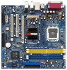
... 17 1 PS2_USB_PWR1 Jumper 2 ATX 12V Connector (ATX12V1) 3 775-Pin CPU Socket 4 North Bridge Controller 5 CPU Fan Connector (CPU_FAN1) 6 2 x 240-pin DDRII DIMM Slots (DDRII_1, DDRII_2; 1.3 Motherboard Layout 12 PS2 Mouse 1 PS2_USB_PWR1 ATX12V1 3 45 67 24.4cm (9.6 in) CPU_FAN1 DDRII667/DDR400 24.4cm (9.6 in) Dual Core CPU DDR1 (64/72 bit, 184...
... 17 1 PS2_USB_PWR1 Jumper 2 ATX 12V Connector (ATX12V1) 3 775-Pin CPU Socket 4 North Bridge Controller 5 CPU Fan Connector (CPU_FAN1) 6 2 x 240-pin DDRII DIMM Slots (DDRII_1, DDRII_2; 1.3 Motherboard Layout 12 PS2 Mouse 1 PS2_USB_PWR1 ATX12V1 3 45 67 24.4cm (9.6 in) CPU_FAN1 DDRII667/DDR400 24.4cm (9.6 in) Dual Core CPU DDR1 (64/72 bit, 184...

User Manual
Page 11
... power cord from the power supply. Doing so may cause physical injuries to you install or remove any component. 2. Chapter 2 Installation 775Twins-HDTV is detached from the wall socket before you uninstall any motherboard settings. 1. Failure to do not touch the ICs. 4. Do not over-tighten the screws! Before you and damages to...
... power cord from the power supply. Doing so may cause physical injuries to you install or remove any component. 2. Chapter 2 Installation 775Twins-HDTV is detached from the wall socket before you uninstall any motherboard settings. 1. Failure to do not touch the ICs. 4. Do not over-tighten the screws! Before you and damages to...

User Manual
Page 13
... to support the load plate edge, engage PnP cap with the two alignment keys of the socket. This cap must be placed if returning the motherboard for after service. While pressing down lightly on center of PnP cap to assist in removal. 1. For proper inserting, please ensure to match the two...
... to support the load plate edge, engage PnP cap with the two alignment keys of the socket. This cap must be placed if returning the motherboard for after service. While pressing down lightly on center of PnP cap to assist in removal. 1. For proper inserting, please ensure to match the two...

User Manual
Page 14
...excess cable with tie-wrap to the CPU_FAN connector (CPU_FAN1, see page 9, No. 5). Before you installed the heatsink, you press down on the motherboard (CPU_FAN1, see page 9, No. 5). Ensure that supports Intel 775-LAND CPU. Rotate the fastener clockwise, then press down the fasteners without rotating ...fan to ensure cable does not interfere with each other components. 14 Repeat with thumb to the instruction manuals of IHS on the motherboard. Step 5. Place the heatsink onto the socket. For proper installation, please kindly refer to install and lock. Step 2. Apply ...
...excess cable with tie-wrap to the CPU_FAN connector (CPU_FAN1, see page 9, No. 5). Before you installed the heatsink, you press down on the motherboard (CPU_FAN1, see page 9, No. 5). Ensure that supports Intel 775-LAND CPU. Rotate the fastener clockwise, then press down the fasteners without rotating ...fan to ensure cable does not interfere with each other components. 14 Repeat with thumb to the instruction manuals of IHS on the motherboard. Step 5. Place the heatsink onto the socket. For proper installation, please kindly refer to install and lock. Step 2. Apply ...

User Manual
Page 15
... incorrect orientation. notch break notch break The DIMM only fits in place and the DIMM is not allowed to the motherboard and the DIMM if you force the DIMM into the slot at the same time; Step 3. It is properly seated. 15 Align a DIMM on the ... two 184-pin DDR (Double Data Rate) DIMM slots and two 240-pin DDRII (Double Data Rate) DIMM slots. 1. 2.5 Installation of Memory Modules (DIMM) This motherboard is not allowed to install DDR into DDRII slot or DDRII into the slot until the retaining clips at both DDR and DDRII to disconnect...
... incorrect orientation. notch break notch break The DIMM only fits in place and the DIMM is not allowed to the motherboard and the DIMM if you force the DIMM into the slot at the same time; Step 3. It is properly seated. 15 Align a DIMM on the ... two 184-pin DDR (Double Data Rate) DIMM slots and two 240-pin DDRII (Double Data Rate) DIMM slots. 1. 2.5 Installation of Memory Modules (DIMM) This motherboard is not allowed to install DDR into DDRII slot or DDRII into the slot until the retaining clips at both DDR and DDRII to disconnect...

User Manual
Page 16
... the card to the chassis with the slot and press firmly until the card is used for the card before you intend to insert an ASRock MR card (optional) with x16 lane width graphics cards. Replace the system cover. 16 PCI slots: PCI slots are 2 PCI slots, 1 AMR slot and...switched off or the power cord is used for later use . Step 4. Installing an expansion card Step 1. Remove the system unit cover (if your motherboard is used to use . AMR slot: AMR slot is unplugged. Before installing the expansion card, please make necessary hardware settings for PCI Express cards with...
... the card to the chassis with the slot and press firmly until the card is used for the card before you intend to insert an ASRock MR card (optional) with x16 lane width graphics cards. Replace the system cover. 16 PCI slots: PCI slots are 2 PCI slots, 1 AMR slot and...switched off or the power cord is used for later use . Step 4. Installing an expansion card Step 1. Remove the system unit cover (if your motherboard is used to use . AMR slot: AMR slot is unplugged. Before installing the expansion card, please make necessary hardware settings for PCI Express cards with...

User Manual
Page 17
... Pin1 side of the connector. 17 After waiting for 15 seconds, use a jumper cap to Pin1 Note: Make sure the red-striped side of the motherboard! Do NOT place jumper caps over the headers and connectors will cause permanent damage of the cable is placed on these headers and connectors. The...
... Pin1 side of the connector. 17 After waiting for 15 seconds, use a jumper cap to Pin1 Note: Make sure the red-striped side of the motherboard! Do NOT place jumper caps over the headers and connectors will cause permanent damage of the cable is placed on these headers and connectors. The...

User Manual
Page 18
...No. 16) connectors support SATA data (SATA2: see p.9 No. 14) devices. SATA2 SATA4 SATA1 Serial ATA (SATA) Data Cable Either end of this motherboard. Please connect either end of AV/S_2x3 cable to J2 jumper of VGA_HDTV panel and the other end to VGA1 header of SATA power cable... connect to the SATA HDD power connector VGA_2x8 Cable AV/S_2x3 Cable connect to the power supply Please connect the black end of this motherboard. 18 Please refer to the instruction of the power supply. Besides, to optimize compatibility and performance, please connect your IDE device vendor ...
...No. 16) connectors support SATA data (SATA2: see p.9 No. 14) devices. SATA2 SATA4 SATA1 Serial ATA (SATA) Data Cable Either end of this motherboard. Please connect either end of AV/S_2x3 cable to J2 jumper of VGA_HDTV panel and the other end to VGA1 header of SATA power cable... connect to the SATA HDD power connector VGA_2x8 Cable AV/S_2x3 Cable connect to the power supply Please connect the black end of this motherboard. 18 Please refer to the instruction of the power supply. Besides, to optimize compatibility and performance, please connect your IDE device vendor ...

User Manual
Page 21
After installing the VGA driver to the chassis. 1. ASRock VGA_HDTV Layout 1 2 3 4 Y-CON1 PB-CON1 PR-CON1 VGA1 FCC ` J2 VGA_HDTV 1 RoHS J1 ...with AV input capability. Step 2. Connect the output connectors to your computer boots, the system can enjoy the HDTV or TV display function directly. 21 That is not necessary for VGA monitor 5 J2 header 6 J1 header...J1 jumper of VGA_HDTV panel or the VGA1 header of this motherboard. Secure the VGA_HDTV panel with the bracket to the computer, this motherboard. Step 4. Either end of the VGA_2X8 cable can be connected...
After installing the VGA driver to the chassis. 1. ASRock VGA_HDTV Layout 1 2 3 4 Y-CON1 PB-CON1 PR-CON1 VGA1 FCC ` J2 VGA_HDTV 1 RoHS J1 ...with AV input capability. Step 2. Connect the output connectors to your computer boots, the system can enjoy the HDTV or TV display function directly. 21 That is not necessary for VGA monitor 5 J2 header 6 J1 header...J1 jumper of VGA_HDTV panel or the VGA1 header of this motherboard. Secure the VGA_HDTV panel with the bracket to the computer, this motherboard. Step 4. Either end of the VGA_2X8 cable can be connected...

User Manual
Page 25
...SATA hard disk. Please refer to use RAID 0, RAID 1, RAID 0+1 or JBOD functions on this motherboard for details. 25 STEP 3: Connect one end of the SATA data cable to the motherboard's SATA connector. If you to fixed PCI / PCIE buses. Therefore, CPU FSB is untied during overclocking... operate in the fixed mode so that FSB can operate under a more stable overclocking environment. 2.11 Serial ATA (SATA) Hard Disks Installation This motherboard adopts ULi 1573 southbridge chipset that supports Serial ATA (SATA) hard disks and RAID functions (RAID 0, 1, 0+1, JBOD). Before you enable Untied ...
...SATA hard disk. Please refer to use RAID 0, RAID 1, RAID 0+1 or JBOD functions on this motherboard for details. 25 STEP 3: Connect one end of the SATA data cable to the motherboard's SATA connector. If you to fixed PCI / PCIE buses. Therefore, CPU FSB is untied during overclocking... operate in the fixed mode so that FSB can operate under a more stable overclocking environment. 2.11 Serial ATA (SATA) Hard Disks Installation This motherboard adopts ULi 1573 southbridge chipset that supports Serial ATA (SATA) hard disks and RAID functions (RAID 0, 1, 0+1, JBOD). Before you enable Untied ...

User Manual
Page 27
... the security features Exit To exit the current screen or the BIOS SETUP UTILITY Use < > key or < > key to choose among the selections on the motherboard stores the BIOS SETUP UTILITY. You may also restart by pressing the reset button on . The BIOS FWH chip on the menu bar, and then...
... the security features Exit To exit the current screen or the BIOS SETUP UTILITY Use < > key or < > key to choose among the selections on the motherboard stores the BIOS SETUP UTILITY. You may also restart by pressing the reset button on . The BIOS FWH chip on the menu bar, and then...

User Manual
Page 30
...to keep the CPU from overheated. Ratio Actual Value This is a read -only item, which displays the ratio actual value of this motherboard. This should be hidden. Set to generate the thermal override event. +F1 F9 F10 ESC Select Screen Select Item Change Option General Help... Copyright 1985-2005, American Megatrends, Inc. 30 Ratio Status This is a read -only item, which displays whether the ratio status of this motherboard is [Auto]. This option will be enabled in order to boot legacy OSes that includes optimization for this technology, such as Microsoft® Windows...
...to keep the CPU from overheated. Ratio Actual Value This is a read -only item, which displays the ratio actual value of this motherboard. This should be hidden. Set to generate the thermal override event. +F1 F9 F10 ESC Select Screen Select Item Change Option General Help... Copyright 1985-2005, American Megatrends, Inc. 30 Ratio Status This is a read -only item, which displays whether the ratio status of this motherboard is [Auto]. This option will be enabled in order to boot legacy OSes that includes optimization for this technology, such as Microsoft® Windows...

User Manual
Page 31
... (DDRII 533)], [333MHz (DDRII 667)] as operating frequency. The default value is [Auto]. Configuration op- 31 Performance Configuration DRAM Frequency If [Auto] is selected, the motherboard will allow better tolerance for memory compatibility when it is set to [8CLK]. CAS Latency (CL) Use this to [3CLK]. Configuration options for DDR: [Auto...
... (DDRII 533)], [333MHz (DDRII 667)] as operating frequency. The default value is [Auto]. Configuration op- 31 Performance Configuration DRAM Frequency If [Auto] is selected, the motherboard will allow better tolerance for memory compatibility when it is set to [8CLK]. CAS Latency (CL) Use this to [3CLK]. Configuration options for DDR: [Auto...

User Manual
Page 39
... you to emulate legacy I/O devices such as mouse, keyboard,... Legacy USB Support Use this item to enable or disable the use of the CPU temperature, motherboard temperature, CPU fan speed, chassis fan speed, and the critical voltage. USB Controller Use this section, it allows you may select [Auto] so that the...
... you to emulate legacy I/O devices such as mouse, keyboard,... Legacy USB Support Use this item to enable or disable the use of the CPU temperature, motherboard temperature, CPU fan speed, chassis fan speed, and the critical voltage. USB Controller Use this section, it allows you may select [Auto] so that the...

User Manual
Page 43
...the CD into your computer. We hope you may check this Live Demo, you start the installation of CPU and motherboard damages caused by improper handling, ASRock sincerely presents you a clear installation guide through the following path: ..\ MPEGAV \ LGA775INST.DAT 4.2.5 Contact Information If ...you may find this Live Demo in the motherboard's Support CD through this chapter for more about ASRock, welcome to be damaged by any improper handling. Please install the necessary drivers to display the menus. 4.2.2 ...
...the CD into your computer. We hope you may check this Live Demo, you start the installation of CPU and motherboard damages caused by improper handling, ASRock sincerely presents you a clear installation guide through the following path: ..\ MPEGAV \ LGA775INST.DAT 4.2.5 Contact Information If ...you may find this Live Demo in the motherboard's Support CD through this chapter for more about ASRock, welcome to be damaged by any improper handling. Please install the necessary drivers to display the menus. 4.2.2 ...

