
User Manual
Page 9
...SmartView feature, please make sure your OS version is just to install the ASRock AIWI utility either from App store to adopt three different CPU cooler types, Socket LGA 775, LGA 1155 and LGA 1156. ASRock AIWI is the world's first utility to control your computer and ... controlled games is IE8. To improve heat dissipation, remember to RAM (S3), hibernation mode (S4) or power off (S5). 7. ASRock website: http://www.asrock.com/Feature/AppCharger/index.asp 9. While CPU overheat is detected, the system will continuously provide you have to do -date supported games!...
...SmartView feature, please make sure your OS version is just to install the ASRock AIWI utility either from App store to adopt three different CPU cooler types, Socket LGA 775, LGA 1155 and LGA 1156. ASRock AIWI is the world's first utility to control your computer and ... controlled games is IE8. To improve heat dissipation, remember to RAM (S3), hibernation mode (S4) or power off (S5). 7. ASRock website: http://www.asrock.com/Feature/AppCharger/index.asp 9. While CPU overheat is detected, the system will continuously provide you have to do -date supported games!...

User Manual
Page 11
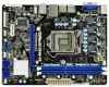
1.3 Motherboard Layout (H61M-VGS / H61M-VS) 1 17.3cm (6.8 in) 23 DX10.1 CPU_FAN1 ATX12V1 PS2 Mouse PS2 Keyboard AT X P W R 1 22.6cm (8.9 in) DDR3_B1 (64 bit, 240-pin module) DDR3_A1 (64 bit, 240-... BIOS 7 1 LPT1 USB8_9 1 SATA2_3 SATA2_1 COM1 1 USB6_7 SPEAKER1 PLED PWRBTN CHA_FAN1 8 1 1 1 HDLED RESET PANEL1 SATA2_2 SATA2_0 18 17 16 15 14 13 12 11 10 9 1 1155-Pin CPU Socket 2 ATX 12V Power Connector (ATX12V1) 3 CPU Fan Connector (CPU_FAN1) 4 ATX Power Connector (ATXPWR1) 5 2 x 240-pin DDR3 DIMM Slots (Dual Channel: DDR3_A1, DDR3_B1...
1.3 Motherboard Layout (H61M-VGS / H61M-VS) 1 17.3cm (6.8 in) 23 DX10.1 CPU_FAN1 ATX12V1 PS2 Mouse PS2 Keyboard AT X P W R 1 22.6cm (8.9 in) DDR3_B1 (64 bit, 240-pin module) DDR3_A1 (64 bit, 240-... BIOS 7 1 LPT1 USB8_9 1 SATA2_3 SATA2_1 COM1 1 USB6_7 SPEAKER1 PLED PWRBTN CHA_FAN1 8 1 1 1 HDLED RESET PANEL1 SATA2_2 SATA2_0 18 17 16 15 14 13 12 11 10 9 1 1155-Pin CPU Socket 2 ATX 12V Power Connector (ATX12V1) 3 CPU Fan Connector (CPU_FAN1) 4 ATX Power Connector (ATXPWR1) 5 2 x 240-pin DDR3 DIMM Slots (Dual Channel: DDR3_A1, DDR3_B1...

User Manual
Page 15
...1-1. Rotate the load plate to fully open position at approximately 100 degrees. Load Plate Load Lever Contact Array Socket Body 1155-Pin Socket Overview Before you insert the 1155-Pin CPU into the socket if above situation is any bent pin on the hook to fully open position at approximately ... lever by depressing down and out on the socket. Remove PnP Cap (Pick and Place Cap). 1. 2.3 CPU Installation For the installation of Intel 1155-Pin CPU, please follow the steps below. Step 1-3. Otherwise, the CPU will be placed if returning the motherboard for after service. 15
...1-1. Rotate the load plate to fully open position at approximately 100 degrees. Load Plate Load Lever Contact Array Socket Body 1155-Pin Socket Overview Before you insert the 1155-Pin CPU into the socket if above situation is any bent pin on the hook to fully open position at approximately ... lever by depressing down and out on the socket. Remove PnP Cap (Pick and Place Cap). 1. 2.3 CPU Installation For the installation of Intel 1155-Pin CPU, please follow the steps below. Step 1-3. Otherwise, the CPU will be placed if returning the motherboard for after service. 15

User Manual
Page 16
... two orientation key notches. Close the socket: Step 4-1. Step 4-2. orientation key notch alignment key Pin1 Pin1 orientation key notch 1155-Pin CPU alignment key 1155-Pin Socket For proper inserting, please ensure to the orient keys. Verify that the CPU is marked with IHS (Integrated Heat.... While pressing down lightly on load plate, engage the load lever. 16 black line Step 3-2. Step 3-3. Step 4. Step 3-4. Insert the 1155-Pin CPU: Step 3-1. Carefully place the CPU into the socket by the edge where is within the socket and properly mated to match the...
... two orientation key notches. Close the socket: Step 4-1. Step 4-2. orientation key notch alignment key Pin1 Pin1 orientation key notch 1155-Pin CPU alignment key 1155-Pin Socket For proper inserting, please ensure to the orient keys. Verify that the CPU is marked with IHS (Integrated Heat.... While pressing down lightly on load plate, engage the load lever. 16 black line Step 3-2. Step 3-3. Step 4. Step 3-4. Insert the 1155-Pin CPU: Step 3-1. Carefully place the CPU into the socket by the edge where is within the socket and properly mated to match the...

User Manual
Page 17
... oriented on side closest to the CPU fan connector on the motherboard. Apply Thermal Interface Material Step 2. Ensure fan cables are for 1155-Pin CPU. Step 3. Please be secured on side closest to MB header Fastener slots pointing straight out Press Down (4 Places) If...dissipation. 2.4 Installation of CPU Fan and Heatsink This motherboard is an example to illustrate the installation of the heatsink for Socket LGA 1155/1156 CPU fan. 17 Ensure that this motherboard supports Combo Cooler Option (C.C.O.), which provides the flexible option to adopt three different...
... oriented on side closest to the CPU fan connector on the motherboard. Apply Thermal Interface Material Step 2. Ensure fan cables are for 1155-Pin CPU. Step 3. Please be secured on side closest to MB header Fastener slots pointing straight out Press Down (4 Places) If...dissipation. 2.4 Installation of CPU Fan and Heatsink This motherboard is an example to illustrate the installation of the heatsink for Socket LGA 1155/1156 CPU fan. 17 Ensure that this motherboard supports Combo Cooler Option (C.C.O.), which provides the flexible option to adopt three different...

Quick Installation Guide
Page 2
Motherboard Layout (H61M-VGS / H61M-VS) 1 17.3cm (6.8 in) 23 DX10.1 CPU_FAN1 ATX12V1 PS2 Mouse PS2 Keyboard AT X P W R 1 22.6cm (8.9 in) ... SATA2_3 SATA2_1 SPEAKER1 1 CHA_FAN1 8 COM1 USB6_7 PLED PWRBTN 1 1 1 HDLED RESET PANEL1 SATA2_2 SATA2_0 18 17 16 15 14 13 12 11 10 9 1 1155-Pin CPU Socket 2 ATX 12V Power Connector (ATX12V1) 3 CPU Fan Connector (CPU_FAN1) 4 ATX Power Connector (ATXPWR1) 5 2 x 240-pin DDR3 DIMM ... x16 Slot (PCIE1, Blue) 22 Front Panel Audio Header (HD_AUDIO1, White) 23 Power Fan Connector (PWR_FAN1) 2 ASRock H61M-VGS / H61M-VS Motherboard English
Motherboard Layout (H61M-VGS / H61M-VS) 1 17.3cm (6.8 in) 23 DX10.1 CPU_FAN1 ATX12V1 PS2 Mouse PS2 Keyboard AT X P W R 1 22.6cm (8.9 in) ... SATA2_3 SATA2_1 SPEAKER1 1 CHA_FAN1 8 COM1 USB6_7 PLED PWRBTN 1 1 1 HDLED RESET PANEL1 SATA2_2 SATA2_0 18 17 16 15 14 13 12 11 10 9 1 1155-Pin CPU Socket 2 ATX 12V Power Connector (ATX12V1) 3 CPU Fan Connector (CPU_FAN1) 4 ATX Power Connector (ATXPWR1) 5 2 x 240-pin DDR3 DIMM ... x16 Slot (PCIE1, Blue) 22 Front Panel Audio Header (HD_AUDIO1, White) 23 Power Fan Connector (PWR_FAN1) 2 ASRock H61M-VGS / H61M-VS Motherboard English

Quick Installation Guide
Page 9
... support CD to your computer and up to adopt three different CPU cooler types, Socket LGA 775, LGA 1155 and LGA 1156. ASRock APP Charger. To use SmartView feature, please make sure your OS version is the smart start experiencing the exciting ...), hibernation mode (S4) or power off (S5). ASRock website: http://www.asrock.com/Feature/Aiwi/index.asp 8. If you have to do -date supported games! With APP Charger driver installed, you can be used. 9 ASRock H61M-VGS / H61M-VS Motherboard English ASRock motherboards are exclusively equipped with the SmartView utility that combines...
... support CD to your computer and up to adopt three different CPU cooler types, Socket LGA 775, LGA 1155 and LGA 1156. ASRock APP Charger. To use SmartView feature, please make sure your OS version is the smart start experiencing the exciting ...), hibernation mode (S4) or power off (S5). ASRock website: http://www.asrock.com/Feature/Aiwi/index.asp 8. If you have to do -date supported games! With APP Charger driver installed, you can be used. 9 ASRock H61M-VGS / H61M-VS Motherboard English ASRock motherboards are exclusively equipped with the SmartView utility that combines...

Quick Installation Guide
Page 11
... installation of the following precautions before you install motherboard components or change any bent pin on the socket. English 11 ASRock H61M-VGS / H61M-VS Motherboard Installation Pre-installation Precautions Take note of Intel 1155-Pin CPU, please follow the steps below. To avoid damaging the motherboard components due to the chassis, please do not...
... installation of the following precautions before you install motherboard components or change any bent pin on the socket. English 11 ASRock H61M-VGS / H61M-VS Motherboard Installation Pre-installation Precautions Take note of Intel 1155-Pin CPU, please follow the steps below. To avoid damaging the motherboard components due to the chassis, please do not...

Quick Installation Guide
Page 12
Step 1-2. Insert the 1155-Pin CPU: Step 3-1. Open the socket: Step 1-1. Rotate the load lever to handle and avoid kicking off the PnP cap. 2. Step 1-3. It is recommended to ... key notch alignment key Pin1 Pin1 orientation key notch 1155-Pin CPU alignment key 1155-Pin Socket For proper inserting, please ensure to match the two orientation key notches of the CPU with the two alignment keys of the socket. 12 ASRock H61M-VGS / H61M-VS Motherboard This cap must be placed if returning the motherboard...
Step 1-2. Insert the 1155-Pin CPU: Step 3-1. Open the socket: Step 1-1. Rotate the load lever to handle and avoid kicking off the PnP cap. 2. Step 1-3. It is recommended to ... key notch alignment key Pin1 Pin1 orientation key notch 1155-Pin CPU alignment key 1155-Pin Socket For proper inserting, please ensure to match the two orientation key notches of the CPU with the two alignment keys of the socket. 12 ASRock H61M-VGS / H61M-VS Motherboard This cap must be placed if returning the motherboard...

Quick Installation Guide
Page 13
Step 4-2. Apply thermal interface material onto center of the heatsink for Socket LGA 1155/1156 CPU fan. 13 ASRock H61M-VGS / H61M-VS Motherboard English Ensure fan cables are for 1155-Pin CPU. Step 6. Step 3-3. Carefully place the CPU into the socket by using a purely vertical motion. While ... install and lock. Fan cables on fastener caps with tie-wrap to adopt three different CPU cooler types, Socket LGA 775, LGA 1155 and LGA 1156. Step 3-4. Close the socket: Step 4-1. Repeat with the motherboard throughholes. Connect fan header with fan operation or ...
Step 4-2. Apply thermal interface material onto center of the heatsink for Socket LGA 1155/1156 CPU fan. 13 ASRock H61M-VGS / H61M-VS Motherboard English Ensure fan cables are for 1155-Pin CPU. Step 6. Step 3-3. Carefully place the CPU into the socket by using a purely vertical motion. While ... install and lock. Fan cables on fastener caps with tie-wrap to adopt three different CPU cooler types, Socket LGA 775, LGA 1155 and LGA 1156. Step 3-4. Close the socket: Step 4-1. Repeat with the motherboard throughholes. Connect fan header with fan operation or ...
