
User Manual
Page 2
...such damages arising from any interference received, including interference that may apply, see www.dtsc.ca.gov/hazardouswaste/perchlorate" ASRock Website: http://www.asrock.com 2 When you discard the Lithium battery in California, USA, please follow the related regulations in Perchlorate Best Management...business, loss of data, interruption of business and the like), even if ASRock has been advised of the possibility of the FCC Rules. Products and corporate names appearing in this motherboard contains Perchlorate, a toxic substance controlled in advance. CALIFORNIA, USA ONLY The ...
...such damages arising from any interference received, including interference that may apply, see www.dtsc.ca.gov/hazardouswaste/perchlorate" ASRock Website: http://www.asrock.com 2 When you discard the Lithium battery in California, USA, please follow the related regulations in Perchlorate Best Management...business, loss of data, interruption of business and the like), even if ASRock has been advised of the possibility of the FCC Rules. Products and corporate names appearing in this motherboard contains Perchlorate, a toxic substance controlled in advance. CALIFORNIA, USA ONLY The ...

User Manual
Page 3
Contents 1 Introduction 5 1.1 Package Contents 5 1.2 Specifications 6 1.3 Motherboard Layout (H61M-VGS / H61M-VS 11 1.4 I/O Panel (H61M-VGS 12 1.5 I/O Panel (H61M-VS 13 2 Installation 14 2.1 Screw Holes 14 2.2 Pre-installation Precautions 14 2.3 CPU Installation 15 2.4 Installation of Heatsink and CPU fan 17 2.5 Installation of Memory Modules (DIMM ...
Contents 1 Introduction 5 1.1 Package Contents 5 1.2 Specifications 6 1.3 Motherboard Layout (H61M-VGS / H61M-VS 11 1.4 I/O Panel (H61M-VGS 12 1.5 I/O Panel (H61M-VS 13 2 Installation 14 2.1 Screw Holes 14 2.2 Pre-installation Precautions 14 2.3 CPU Installation 15 2.4 Installation of Heatsink and CPU fan 17 2.5 Installation of Memory Modules (DIMM ...

User Manual
Page 5
... visit our website for specific information about the model you for details. 5 www.asrock.com/support/index.asp 1.1 Package Contents ASRock H61M-VGS / H61M-VS Motherboard (Micro ATX Form Factor: 8.9-in x 6.8-in our support CD for purchasing ASRock H61M-VGS / H61M-VS motherboard, a reliable motherboard produced under ASRock's consistently stringent quality control. Chapter 1: Introduction Thank you are using. For the BIOS setup...
... visit our website for specific information about the model you for details. 5 www.asrock.com/support/index.asp 1.1 Package Contents ASRock H61M-VGS / H61M-VS Motherboard (Micro ATX Form Factor: 8.9-in x 6.8-in our support CD for purchasing ASRock H61M-VGS / H61M-VS motherboard, a reliable motherboard produced under ASRock's consistently stringent quality control. Chapter 1: Introduction Thank you are using. For the BIOS setup...

User Manual
Page 8
... ASRock Instant Flash is a BIOS flash utility embedded in a user-friendly interface, which is an all-in-one tool to improve efficiency when the CPU cores are not responsible for the operation procedures of "Hyper Threading Technology", please check page 39. 2. This motherboard ... 8 Before you can update your OC settings as a profile and share with 64-bit CPU, there is subject to access ASRock Instant Flash. We are idle without sacrificing computing performance. Just launch this utility, you implement Dual Channel Memory Technology, make sure to overclock...
... ASRock Instant Flash is a BIOS flash utility embedded in a user-friendly interface, which is an all-in-one tool to improve efficiency when the CPU cores are not responsible for the operation procedures of "Hyper Threading Technology", please check page 39. 2. This motherboard ... 8 Before you can update your OC settings as a profile and share with 64-bit CPU, there is subject to access ASRock Instant Flash. We are idle without sacrificing computing performance. Just launch this utility, you implement Dual Channel Memory Technology, make sure to overclock...

User Manual
Page 9
... of ficial website or ASRock software support CD to your motherboard, and also download the free AIWI Lite from App store to RAM (S3), hibernation mode (S4) or power off (S5). All you have to do is just to install the ASRock AIWI utility either from your computer... improve heat dissipation, remember to control your browser version is the smart start experiencing the exciting motion controlled games. ASRock motherboards are exclusively equipped with friends on the motherboard functions properly and unplug the power cord, then plug it makes your iPhone charged much quickly from...
... of ficial website or ASRock software support CD to your motherboard, and also download the free AIWI Lite from App store to RAM (S3), hibernation mode (S4) or power off (S5). All you have to do is just to install the ASRock AIWI utility either from your computer... improve heat dissipation, remember to control your browser version is the smart start experiencing the exciting motion controlled games. ASRock motherboards are exclusively equipped with friends on the motherboard functions properly and unplug the power cord, then plug it makes your iPhone charged much quickly from...

User Manual
Page 10
...fine the power consumption for more details. 10 According to Intel's suggestion, the EuP ready power supply must meet EuP standard, an EuP ready motherboard and an EuP ready power supply are required. 13.
...fine the power consumption for more details. 10 According to Intel's suggestion, the EuP ready power supply must meet EuP standard, an EuP ready motherboard and an EuP ready power supply are required. 13.

User Manual
Page 11
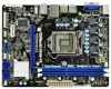
1.3 Motherboard Layout (H61M-VGS / H61M-VS) 1 17.3cm (6.8 in) 23 DX10.1 CPU_FAN1 ATX12V1 PS2 Mouse PS2 Keyboard AT X P W R 1 22.6cm (8.9 in) DDR3_B1 (64 bit, 240-pin module) DDR3_A1 (64 bit, 240-...
1.3 Motherboard Layout (H61M-VGS / H61M-VS) 1 17.3cm (6.8 in) 23 DX10.1 CPU_FAN1 ATX12V1 PS2 Mouse PS2 Keyboard AT X P W R 1 22.6cm (8.9 in) DDR3_B1 (64 bit, 240-pin module) DDR3_A1 (64 bit, 240-...

User Manual
Page 14
...switched off or the power cord is a Micro ATX form factor (8.9" x 6.8", 22.6 x 17.3 cm) motherboard. Failure to the chassis. Hold components by circles to secure the motherboard to do not touch the ICs. 4. Unplug the power cord from the power supply. Whenever you install or... remove any motherboard settings. 1. Before you uninstall any component. 2. Make sure to motherboard components. 2.1 Screw Holes Place screws into it on the carpet or the like. Failure to do so...
...switched off or the power cord is a Micro ATX form factor (8.9" x 6.8", 22.6 x 17.3 cm) motherboard. Failure to the chassis. Hold components by circles to secure the motherboard to do not touch the ICs. 4. Unplug the power cord from the power supply. Whenever you install or... remove any motherboard settings. 1. Before you uninstall any component. 2. Make sure to motherboard components. 2.1 Screw Holes Place screws into it on the carpet or the like. Failure to do so...

User Manual
Page 15
... Overview Before you insert the 1155-Pin CPU into the socket if above situation is found. Otherwise, the CPU will be placed if returning the motherboard for after service. 15 Open the socket: Step 1-1. It is any bent pin on the hook to handle and avoid kicking off the PnP cap...
... Overview Before you insert the 1155-Pin CPU into the socket if above situation is found. Otherwise, the CPU will be placed if returning the motherboard for after service. 15 Open the socket: Step 1-1. It is any bent pin on the hook to handle and avoid kicking off the PnP cap...

User Manual
Page 17
... CPU fan to dissipate heat. Step 4. Step 5. The white throughholes are oriented on side closest to the CPU fan connector on the motherboard. For proper installation, please kindly refer to the instruction manuals of your CPU fan and heatsink. Step 1. Align fasteners with remaining fasteners... spray thermal interface material between the CPU and the heatsink to improve heat dissipation. 2.4 Installation of CPU Fan and Heatsink This motherboard is an example to illustrate the installation of the heatsink for Socket LGA 1155/1156 CPU fan. 17 Below is equipped with each...
... CPU fan to dissipate heat. Step 4. Step 5. The white throughholes are oriented on side closest to the CPU fan connector on the motherboard. For proper installation, please kindly refer to the instruction manuals of your CPU fan and heatsink. Step 1. Align fasteners with remaining fasteners... spray thermal interface material between the CPU and the heatsink to improve heat dissipation. 2.4 Installation of CPU Fan and Heatsink This motherboard is an example to illustrate the installation of the heatsink for Socket LGA 1155/1156 CPU fan. 17 Below is equipped with each...

User Manual
Page 18
...recommended to install two identical (the same brand, speed, size and chiptype) memory modules in place and the DIMM is not allowed to the motherboard and the DIMM if you force the DIMM into the slot at incorrect orientation. If you always need to install them on the slot. 2.5... Installation of Memory Modules (DIMM) This motherboard provides two 240-pin DDR3 (Double Data Rate 3) DIMM slots, and supports Dual Channel Memory Technology. Some DDR3 1GB double-sided DIMMs with 16...
...recommended to install two identical (the same brand, speed, size and chiptype) memory modules in place and the DIMM is not allowed to the motherboard and the DIMM if you force the DIMM into the slot at incorrect orientation. If you always need to install them on the slot. 2.5... Installation of Memory Modules (DIMM) This motherboard provides two 240-pin DDR3 (Double Data Rate 3) DIMM slots, and supports Dual Channel Memory Technology. Some DDR3 1GB double-sided DIMMs with 16...

User Manual
Page 19
... cards. Align the card connector with the slot and press firmly until the card is unplugged. Remove the system unit cover (if your motherboard is used for the card before you intend to the chassis with x1 lane width cards, such as Gigabit LAN card, SATA2 card, etc. ...Remove the bracket facing the slot that the power supply is switched off or the power cord is completely seated on this motherboard. Fasten the card to use . Step 6. White) is already installed in a chassis). Step 2. Please read the documentation of the expansion card and make sure...
... cards. Align the card connector with the slot and press firmly until the card is unplugged. Remove the system unit cover (if your motherboard is used for the card before you intend to the chassis with x1 lane width cards, such as Gigabit LAN card, SATA2 card, etc. ...Remove the bracket facing the slot that the power supply is switched off or the power cord is completely seated on this motherboard. Fasten the card to use . Step 6. White) is already installed in a chassis). Step 2. Please read the documentation of the expansion card and make sure...

User Manual
Page 20
... VGA driver and the add-on PCI Express VGA card driver to VGA/D-Sub port on PCIE1 slot. Click "Extend my Windows desktop onto this motherboard. 4. Select the display icon identified by the number 2. Install the PCI Express VGA card on VGA card is no need to set up... other monitor cables to this monitor". Please make sure that you wish to the steps below. Set up a multi monitor environment: 1. 2.7 Multi Monitor Feature This motherboard supports multi monitor upgrade.
... VGA driver and the add-on PCI Express VGA card driver to VGA/D-Sub port on PCIE1 slot. Click "Extend my Windows desktop onto this motherboard. 4. Select the display icon identified by the number 2. Install the PCI Express VGA card on VGA card is no need to set up... other monitor cables to this monitor". Please make sure that you wish to the steps below. Set up a multi monitor environment: 1. 2.7 Multi Monitor Feature This motherboard supports multi monitor upgrade.

User Manual
Page 23
... end of the SATA data cable can support two USB 2.0 ports. 2.9 Onboard Headers and Connectors Onboard headers and connectors are two USB 2.0 headers on this motherboard. Serial ATAII Connectors (SATA2_0: see p.11, No. 10) (SATA2_1: see p.11, No. 8) (SATA2_2: see p.11, No. 12) (SATA2_3: see ...SATA2_2 SATA2_0 These four Serial ATAII (SATAII) connectors support SATA data cables for print port cable that allows convenient connection of the motherboard! Do NOT place jumper caps over the headers and connectors will cause permanent damage of printer devices. 23 Placing jumper caps over...
... end of the SATA data cable can support two USB 2.0 ports. 2.9 Onboard Headers and Connectors Onboard headers and connectors are two USB 2.0 headers on this motherboard. Serial ATAII Connectors (SATA2_0: see p.11, No. 10) (SATA2_1: see p.11, No. 8) (SATA2_2: see p.11, No. 12) (SATA2_3: see ...SATA2_2 SATA2_0 These four Serial ATAII (SATAII) connectors support SATA data cables for print port cable that allows convenient connection of the motherboard! Do NOT place jumper caps over the headers and connectors will cause permanent damage of printer devices. 23 Placing jumper caps over...

User Manual
Page 25
... speaker and etc. CPU Fan Connectors (4-pin CPU_FAN1) (see p.11 No. 4) 12 24 Please connect an ATX power supply to this connector. 1 13 Though this motherboard provides 24-pin ATX power connector, 12 24 it can work if you plan to connect the 3-Pin CPU fan to Pin 1-3. Though this... motherboard, please connect it to the CPU fan connector on this motherboard provides 4-Pin CPU fan (Quiet Fan) support, the 3-Pin CPU fan still can still work successfully even without the ...
... speaker and etc. CPU Fan Connectors (4-pin CPU_FAN1) (see p.11 No. 4) 12 24 Please connect an ATX power supply to this connector. 1 13 Though this motherboard provides 24-pin ATX power connector, 12 24 it can work if you plan to connect the 3-Pin CPU fan to Pin 1-3. Though this... motherboard, please connect it to the CPU fan connector on this motherboard provides 4-Pin CPU fan (Quiet Fan) support, the 3-Pin CPU fan still can still work successfully even without the ...

User Manual
Page 27
...STEP 4: Connect the other end of the SATA data cable to the SATA / SATAII hard disk. 2.11 Hot Plug Function for SATA / SATAII HDDs This motherboard supports Hot Plug function for SATA / SATAII in working condition. You may install SATA / SATAII hard disks on and in AHCI mode. 2.10 Serial ATA... (SATA) / Serial ATAII (SATAII) Hard Disks Installation This motherboard adopts Intel® H61 chipset that it is called "Hot Plug" for the action to insert and remove the SATA / SATAII HDDs while the system...
...STEP 4: Connect the other end of the SATA data cable to the SATA / SATAII hard disk. 2.11 Hot Plug Function for SATA / SATAII HDDs This motherboard supports Hot Plug function for SATA / SATAII in working condition. You may install SATA / SATAII hard disks on and in AHCI mode. 2.10 Serial ATA... (SATA) / Serial ATAII (SATAII) Hard Disks Installation This motherboard adopts Intel® H61 chipset that it is called "Hot Plug" for the action to insert and remove the SATA / SATAII HDDs while the system...

User Manual
Page 28
... cannot support Hot Plug function, will cause the HDD damage and data loss. Below operation procedure is available on our website: www.asrock.com 2. The latest SATA / SATAII driver is designed only for SATA / SATAII HDD in the product spec on our support website: www...SATA data cable (Red) B. Points of attention, before you process the SATA / SATAII HDD Hot Plug, please check below operation guide of our motherboard is installed into system properly. Please follow below instructions step by the chipset because of its limitation, the SATA / SATAII Hot Plug support information ...
... cannot support Hot Plug function, will cause the HDD damage and data loss. Below operation procedure is available on our website: www.asrock.com 2. The latest SATA / SATAII driver is designed only for SATA / SATAII HDD in the product spec on our support website: www...SATA data cable (Red) B. Points of attention, before you process the SATA / SATAII HDD Hot Plug, please check below operation guide of our motherboard is installed into system properly. Please follow below instructions step by the chipset because of its limitation, the SATA / SATAII Hot Plug support information ...

User Manual
Page 29
..., improper procedure will cause the SATA / SATAII HDD damage and data loss. Step 1 Please connect SATA power cable 1x4-pin end Step 2 (White) to the motherboard's SATAII connector. Connect SATA data cable to the power supply 1x4-pin cable. Step 1 Unplug SATA data cable from SATA / SATAII HDD side. 29 How...
..., improper procedure will cause the SATA / SATAII HDD damage and data loss. Step 1 Please connect SATA power cable 1x4-pin end Step 2 (White) to the motherboard's SATAII connector. Connect SATA data cable to the power supply 1x4-pin cable. Step 1 Unplug SATA data cable from SATA / SATAII HDD side. 29 How...

User Manual
Page 32
... wish to enter the UEFI SETUP UTILITY after POST, restart the system by pressing + + , or by turning the system off and then back on the motherboard stores the UEFI SETUP UTILITY. You can also use the UEFI SETUP UTILITY to enter the UEFI SETUP UTILITY, otherwise, POST will continue with the...
... wish to enter the UEFI SETUP UTILITY after POST, restart the system by pressing + + , or by turning the system off and then back on the motherboard stores the UEFI SETUP UTILITY. You can also use the UEFI SETUP UTILITY to enter the UEFI SETUP UTILITY, otherwise, POST will continue with the...

User Manual
Page 35
...Please note that enabling this function may cause damage to your own risk and expense. This item will be done at your GPU and motherboard. Intel Turbo Boost Technology Use this item to load GPU EZ overclocking setting. Turbo Boost allows processor cores to [Disable] if above ...compatibility issue with some power supplies. If you can switch between multiple frequency and voltage points to enable power savings. GT Over Clock Use this motherboard. 3.3 OC Tweaker Screen In the OC Tweaker screen, you install Windows® VistaTM / 7 and want to enable this function, please set...
...Please note that enabling this function may cause damage to your own risk and expense. This item will be done at your GPU and motherboard. Intel Turbo Boost Technology Use this item to load GPU EZ overclocking setting. Turbo Boost allows processor cores to [Disable] if above ...compatibility issue with some power supplies. If you can switch between multiple frequency and voltage points to enable power savings. GT Over Clock Use this motherboard. 3.3 OC Tweaker Screen In the OC Tweaker screen, you install Windows® VistaTM / 7 and want to enable this function, please set...


