
User Manual
Page 9
... function of charging your PC games. Combo Cooler Option (C.C.O.) provides the flexible option to adopt three different CPU cooler types, Socket LGA 775, LGA 1155 and LGA 1156. ASRock website: http://www.asrock.com/Feature/Aiwi/index.asp 8. The performance may depend on -the-go. 7. If you have to do -date supported games...
... function of charging your PC games. Combo Cooler Option (C.C.O.) provides the flexible option to adopt three different CPU cooler types, Socket LGA 775, LGA 1155 and LGA 1156. ASRock website: http://www.asrock.com/Feature/Aiwi/index.asp 8. The performance may depend on -the-go. 7. If you have to do -date supported games...

User Manual
Page 11
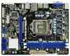
1.3 Motherboard Layout (H61M-VGS / H61M-VS) 1 17.3cm (6.8 in) 23 DX10.1 CPU_FAN1 ATX12V1 PS2 Mouse PS2 Keyboard AT X P W R 1 22.6cm (8.9 in) DDR3_B1 (64 bit, 240-pin module) DDR3_A1 (64 bit, 240-... 7 1 LPT1 USB8_9 1 SATA2_3 SATA2_1 COM1 1 USB6_7 SPEAKER1 PLED PWRBTN CHA_FAN1 8 1 1 1 HDLED RESET PANEL1 SATA2_2 SATA2_0 18 17 16 15 14 13 12 11 10 9 1 1155-Pin CPU Socket 2 ATX 12V Power Connector (ATX12V1) 3 CPU Fan Connector (CPU_FAN1) 4 ATX Power Connector (ATXPWR1) 5 2 x 240-pin DDR3 DIMM Slots (Dual Channel: DDR3_A1, DDR3_B1, Blue) 6 Intel...
1.3 Motherboard Layout (H61M-VGS / H61M-VS) 1 17.3cm (6.8 in) 23 DX10.1 CPU_FAN1 ATX12V1 PS2 Mouse PS2 Keyboard AT X P W R 1 22.6cm (8.9 in) DDR3_B1 (64 bit, 240-pin module) DDR3_A1 (64 bit, 240-... 7 1 LPT1 USB8_9 1 SATA2_3 SATA2_1 COM1 1 USB6_7 SPEAKER1 PLED PWRBTN CHA_FAN1 8 1 1 1 HDLED RESET PANEL1 SATA2_2 SATA2_0 18 17 16 15 14 13 12 11 10 9 1 1155-Pin CPU Socket 2 ATX 12V Power Connector (ATX12V1) 3 CPU Fan Connector (CPU_FAN1) 4 ATX Power Connector (ATXPWR1) 5 2 x 240-pin DDR3 DIMM Slots (Dual Channel: DDR3_A1, DDR3_B1, Blue) 6 Intel...

User Manual
Page 15
... tab to clear retention tab. This cap must be seriously damaged. Load Plate Load Lever Contact Array Socket Body 1155-Pin Socket Overview Before you insert the 1155-Pin CPU into the socket if above situation is any bent pin on the hook to handle and avoid kicking off the PnP cap.... 2. Disengaging the lever by depressing down and out on the socket. Step 1-2. 2.3 CPU Installation For the installation of Intel 1155-Pin CPU, please follow the steps below. Otherwise, the CPU will be placed if returning the motherboard for after ...
... tab to clear retention tab. This cap must be seriously damaged. Load Plate Load Lever Contact Array Socket Body 1155-Pin Socket Overview Before you insert the 1155-Pin CPU into the socket if above situation is any bent pin on the hook to handle and avoid kicking off the PnP cap.... 2. Disengaging the lever by depressing down and out on the socket. Step 1-2. 2.3 CPU Installation For the installation of Intel 1155-Pin CPU, please follow the steps below. Otherwise, the CPU will be placed if returning the motherboard for after ...

User Manual
Page 16
...down lightly on load plate, engage the load lever. 16 orientation key notch alignment key Pin1 Pin1 orientation key notch 1155-Pin CPU alignment key 1155-Pin Socket For proper inserting, please ensure to the orient keys. Verify that the CPU is marked with black line. Carefully... place the CPU into the socket by the edge where is within the socket and properly mated to match the two orientation key notches of the socket. black line Step 3-2. Locate Pin1 and the two orientation key notches. Step 3-3. Step 4. Insert the 1155-Pin CPU: Step 3-1. Step ...
...down lightly on load plate, engage the load lever. 16 orientation key notch alignment key Pin1 Pin1 orientation key notch 1155-Pin CPU alignment key 1155-Pin Socket For proper inserting, please ensure to the orient keys. Verify that the CPU is marked with black line. Carefully... place the CPU into the socket by the edge where is within the socket and properly mated to match the two orientation key notches of the socket. black line Step 3-2. Locate Pin1 and the two orientation key notches. Step 3-3. Step 4. Insert the 1155-Pin CPU: Step 3-1. Step ...

User Manual
Page 17
... components. 2.4 Installation of CPU Fan and Heatsink This motherboard is an example to illustrate the installation of the heatsink for Socket LGA 1155/1156 CPU fan. 17 Ensure that this motherboard supports Combo Cooler Option (C.C.O.), which provides the flexible option to adopt... three different CPU cooler types, Socket LGA 775, LGA 1155 and LGA 1156. For proper installation, please kindly refer to ensure cable does not interfere with remaining fasteners. Place the...
... components. 2.4 Installation of CPU Fan and Heatsink This motherboard is an example to illustrate the installation of the heatsink for Socket LGA 1155/1156 CPU fan. 17 Ensure that this motherboard supports Combo Cooler Option (C.C.O.), which provides the flexible option to adopt... three different CPU cooler types, Socket LGA 775, LGA 1155 and LGA 1156. For proper installation, please kindly refer to ensure cable does not interfere with remaining fasteners. Place the...

Quick Installation Guide
Page 2
... 7 1 LPT1 USB8_9 1 SATA2_3 SATA2_1 SPEAKER1 1 CHA_FAN1 8 COM1 USB6_7 PLED PWRBTN 1 1 1 HDLED RESET PANEL1 SATA2_2 SATA2_0 18 17 16 15 14 13 12 11 10 9 1 1155-Pin CPU Socket 2 ATX 12V Power Connector (ATX12V1) 3 CPU Fan Connector (CPU_FAN1) 4 ATX Power Connector (ATXPWR1) 5 2 x 240-pin DDR3 DIMM Slots (Dual Channel: DDR3_A1, DDR3_B1, Blue) 6 Intel..., White) 20 Clear CMOS Jumper (CLRCMOS1) 21 PCI Express 2.0 x16 Slot (PCIE1, Blue) 22 Front Panel Audio Header (HD_AUDIO1, White) 23 Power Fan Connector (PWR_FAN1) 2 ASRock H61M-VGS / H61M-VS Motherboard English
... 7 1 LPT1 USB8_9 1 SATA2_3 SATA2_1 SPEAKER1 1 CHA_FAN1 8 COM1 USB6_7 PLED PWRBTN 1 1 1 HDLED RESET PANEL1 SATA2_2 SATA2_0 18 17 16 15 14 13 12 11 10 9 1 1155-Pin CPU Socket 2 ATX 12V Power Connector (ATX12V1) 3 CPU Fan Connector (CPU_FAN1) 4 ATX Power Connector (ATXPWR1) 5 2 x 240-pin DDR3 DIMM Slots (Dual Channel: DDR3_A1, DDR3_B1, Blue) 6 Intel..., White) 20 Clear CMOS Jumper (CLRCMOS1) 21 PCI Express 2.0 x16 Slot (PCIE1, Blue) 22 Front Panel Audio Header (HD_AUDIO1, White) 23 Power Fan Connector (PWR_FAN1) 2 ASRock H61M-VGS / H61M-VS Motherboard English

Quick Installation Guide
Page 9
...devices via Bluetooth or WiFi networks, then you can be used. 9 ASRock H61M-VGS / H61M-VS Motherboard English Connecting your iPhone/iPod touch. ASRock APP Charger. ASRock website: http://www.asrock.com/Feature/AppCharger/index.asp 9. ASRock motherboards are exclusively equipped with the SmartView utility that helps you to ...please make sure your OS version is IE8. To improve heat dissipation, remember to adopt three different CPU cooler types, Socket LGA 775, LGA 1155 and LGA 1156. Simply installing the APP Charger driver, it back again. While CPU overheat is no longer only ...
...devices via Bluetooth or WiFi networks, then you can be used. 9 ASRock H61M-VGS / H61M-VS Motherboard English Connecting your iPhone/iPod touch. ASRock APP Charger. ASRock website: http://www.asrock.com/Feature/AppCharger/index.asp 9. ASRock motherboards are exclusively equipped with the SmartView utility that helps you to ...please make sure your OS version is IE8. To improve heat dissipation, remember to adopt three different CPU cooler types, Socket LGA 775, LGA 1155 and LGA 1156. Simply installing the APP Charger driver, it back again. While CPU overheat is no longer only ...

Quick Installation Guide
Page 11
... Plate Contact Array Load Lever Socket Body 1155-Pin Socket Overview Before you uninstall any bent pin on the socket. Unplug the power cord from the wall socket before touching any motherboard settings. 1. When placing screws into the socket if above situation is any ... grounded wrist strap or touch a safety grounded object before you handle components. 3. English 11 ASRock H61M-VGS / H61M-VS Motherboard Installation Pre-installation Precautions Take note of Intel 1155-Pin CPU, please follow the steps below. Failure to static electricity, NEVER place your motherboard ...
... Plate Contact Array Load Lever Socket Body 1155-Pin Socket Overview Before you uninstall any bent pin on the socket. Unplug the power cord from the wall socket before touching any motherboard settings. 1. When placing screws into the socket if above situation is any ... grounded wrist strap or touch a safety grounded object before you handle components. 3. English 11 ASRock H61M-VGS / H61M-VS Motherboard Installation Pre-installation Precautions Take note of Intel 1155-Pin CPU, please follow the steps below. Failure to static electricity, NEVER place your motherboard ...

Quick Installation Guide
Page 12
.... Locate Pin1 and the two orientation key notches. orientation key notch alignment key Pin1 Pin1 orientation key notch 1155-Pin CPU alignment key 1155-Pin Socket For proper inserting, please ensure to fully open position at approximately 100 degrees. Step 1-3. Rotate the load ...Integrated Heat Sink) up. Insert the 1155-Pin CPU: Step 3-1. Step 2. It is recommended to use the cap tab to clear retention tab. Orient the CPU with the two alignment keys of the socket. 12 ASRock H61M-VGS / H61M-VS Motherboard Step 3-2. Open the socket: Step 1-1. Remove PnP Cap (...
.... Locate Pin1 and the two orientation key notches. orientation key notch alignment key Pin1 Pin1 orientation key notch 1155-Pin CPU alignment key 1155-Pin Socket For proper inserting, please ensure to fully open position at approximately 100 degrees. Step 1-3. Rotate the load ...Integrated Heat Sink) up. Insert the 1155-Pin CPU: Step 3-1. Step 2. It is recommended to use the cap tab to clear retention tab. Orient the CPU with the two alignment keys of the socket. 12 ASRock H61M-VGS / H61M-VS Motherboard Step 3-2. Open the socket: Step 1-1. Remove PnP Cap (...

Quick Installation Guide
Page 13
... with the CPU fan connector on side closest to the instruction manuals of the heatsink for Socket LGA 1155/1156 CPU fan. 13 ASRock H61M-VGS / H61M-VS Motherboard English Step 5. Secure excess cable with fan operation or contact other components. Step 3-3. Step 3. The white throughholes are oriented on the motherboard. Apply Thermal ...
... with the CPU fan connector on side closest to the instruction manuals of the heatsink for Socket LGA 1155/1156 CPU fan. 13 ASRock H61M-VGS / H61M-VS Motherboard English Step 5. Secure excess cable with fan operation or contact other components. Step 3-3. Step 3. The white throughholes are oriented on the motherboard. Apply Thermal ...
