
User Manual
Page 2
...may apply, see www.dtsc.ca.gov/hazardouswaste/ perchlorate" ASRock Website: http://www.asrock.com When you discard the Lithium battery in California, USA, please follow the related regulations in this motherboard contains Perchlorate, a toxic substance controlled in Perchlorate Best ...means, except duplication of this documentation. "Perchlorate Material-special handling may not be constructed as a commitment by ASRock. ASRock assumes no event shall ASRock, its directors, officers, employees, or agents be liable for any indirect, special, incidental, or consequential damages...
...may apply, see www.dtsc.ca.gov/hazardouswaste/ perchlorate" ASRock Website: http://www.asrock.com When you discard the Lithium battery in California, USA, please follow the related regulations in this motherboard contains Perchlorate, a toxic substance controlled in Perchlorate Best ...means, except duplication of this documentation. "Perchlorate Material-special handling may not be constructed as a commitment by ASRock. ASRock assumes no event shall ASRock, its directors, officers, employees, or agents be liable for any indirect, special, incidental, or consequential damages...

User Manual
Page 4
Contents Chapter 1 Introduction 1 1.1 Package Contents 1 1.2 Specifications 2 1.3 Motherboard Layout 7 1.4 I/O Panel 9 1.5 WiFi-802.11ac Module and ASRock WiFi 2.4/5 GHz Antenna (for X370 Killer SLI/ac only) 11 Chapter 2 Installation 13 2.1 Installing the CPU 14 2.2 Installing the CPU Fan and Heatsink 16 2.3 Installing Memory Modules (DIMM) 25 2.4 Expansion Slots (PCI Express ...
Contents Chapter 1 Introduction 1 1.1 Package Contents 1 1.2 Specifications 2 1.3 Motherboard Layout 7 1.4 I/O Panel 9 1.5 WiFi-802.11ac Module and ASRock WiFi 2.4/5 GHz Antenna (for X370 Killer SLI/ac only) 11 Chapter 2 Installation 13 2.1 Installing the CPU 14 2.2 Installing the CPU Fan and Heatsink 16 2.3 Installing Memory Modules (DIMM) 25 2.4 Expansion Slots (PCI Express ...

User Manual
Page 7
...; ASRock X370 Killer SLI/ac / X370 Killer SLI Motherboard (ATX Form Factor) • ASRock X370 Killer SLI/ac / X370 Killer SLI Quick Installation Guide • ASRock X370 Killer SLI/ac / X370 Killer SLI Support CD • 1 x I/O Panel Shield • 2 x Serial ATA (SATA) Data Cables (Optional) • 1 x ASRock SLI_HB_Bridge_2S Card (Optional) • 3 x Screws for M.2 Socket (Optional) (for X370 Killer SLI only) • 2 x Screws for M.2 Socket (Optional) (for X370 Killer SLI/ac only) • 2 x ASRock WiFi 2.4/5 GHz Antennas (Optional) (for purchasing ASRock X370 Killer SLI/ac / X370...
...; ASRock X370 Killer SLI/ac / X370 Killer SLI Motherboard (ATX Form Factor) • ASRock X370 Killer SLI/ac / X370 Killer SLI Quick Installation Guide • ASRock X370 Killer SLI/ac / X370 Killer SLI Support CD • 1 x I/O Panel Shield • 2 x Serial ATA (SATA) Data Cables (Optional) • 1 x ASRock SLI_HB_Bridge_2S Card (Optional) • 3 x Screws for M.2 Socket (Optional) (for X370 Killer SLI only) • 2 x Screws for M.2 Socket (Optional) (for X370 Killer SLI/ac only) • 2 x ASRock WiFi 2.4/5 GHz Antennas (Optional) (for purchasing ASRock X370 Killer SLI/ac / X370...
User Manual
Page 17
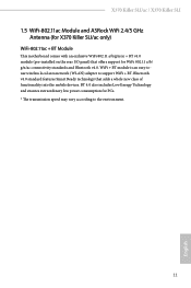
... an easy-touse wireless local area network (WLAN) adapter to the environment. 11 English X370 Killer SLI/ac / X370 Killer SLI 1.5 WiFi-802.11ac Module and ASRock WiFi 2.4/5 GHz Antenna (for X370 Killer SLI/ac only) WiFi-802.11ac + BT Module This motherboard comes with an exclusive WiFi 802.11 a/b/g/n/ac + BT v4.0 module (pre-installed on the rear I/O panel) that adds a whole new...
... an easy-touse wireless local area network (WLAN) adapter to the environment. 11 English X370 Killer SLI/ac / X370 Killer SLI 1.5 WiFi-802.11ac Module and ASRock WiFi 2.4/5 GHz Antenna (for X370 Killer SLI/ac only) WiFi-802.11ac + BT Module This motherboard comes with an exclusive WiFi 802.11 a/b/g/n/ac + BT v4.0 module (pre-installed on the rear I/O panel) that adds a whole new...
User Manual
Page 19
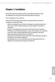
... English Doing so may cause physical injuries to do not overtighten the screws! X370 Killer SLI/ac / X370 Killer SLI Chapter 2 Installation This is a ATX form factor motherboard. Before you install the motherboard, study the configuration of the following precautions before you install motherboard components or change any components, place them on a carpet. Pre-installation Precautions Take note of your...
... English Doing so may cause physical injuries to do not overtighten the screws! X370 Killer SLI/ac / X370 Killer SLI Chapter 2 Installation This is a ATX form factor motherboard. Before you install the motherboard, study the configuration of the following precautions before you install motherboard components or change any components, place them on a carpet. Pre-installation Precautions Take note of your...

User Manual
Page 22
Please turn off the power or remove the power cord before changing a CPU or heatsink. 2.2 Installing the CPU Fan and Heatsink After you install the CPU into this motherboard, it is necessary to install a larger heatsink and cooling fan to improve heat dissipation. Installing the CPU Box Cooler SR1 1 2 16 English You also need to spray thermal grease between the CPU and the heatsink to dissipate heat. Make sure that the CPU and the heatsink are securely fastened and in good contact with each other.
Please turn off the power or remove the power cord before changing a CPU or heatsink. 2.2 Installing the CPU Fan and Heatsink After you install the CPU into this motherboard, it is necessary to install a larger heatsink and cooling fan to improve heat dissipation. Installing the CPU Box Cooler SR1 1 2 16 English You also need to spray thermal grease between the CPU and the heatsink to dissipate heat. Make sure that the CPU and the heatsink are securely fastened and in good contact with each other.

User Manual
Page 31
X370 Killer SLI/ac / X370 Killer SLI 2.3 Installing Memory Modules (DIMM) This motherboard provides four 288-pin DDR4 (Double Data Rate 4) DIMM slots, and supports Dual Channel Memory Technology. 1. It is unable to activate Dual Channel Memory Technology ... 1866 1866 Ryzen CPUs: UDIMM Memory Slot A1 A2 B1 B2 Frequency (Mhz) - SR 2667 - DR - DR - - - SR - SR - SR - - - DR - - 2667 - DR - otherwise, this motherboard and DIMM may be damaged. DR 2400-2667 SR SR SR SR 2133-2400 SR/DR DR SR/DR DR 1866-2133 SR: Single rank...
X370 Killer SLI/ac / X370 Killer SLI 2.3 Installing Memory Modules (DIMM) This motherboard provides four 288-pin DDR4 (Double Data Rate 4) DIMM slots, and supports Dual Channel Memory Technology. 1. It is unable to activate Dual Channel Memory Technology ... 1866 1866 Ryzen CPUs: UDIMM Memory Slot A1 A2 B1 B2 Frequency (Mhz) - SR 2667 - DR - DR - - - SR - SR - SR - - - DR - - 2667 - DR - otherwise, this motherboard and DIMM may be damaged. DR 2400-2667 SR SR SR SR 2133-2400 SR/DR DR SR/DR DR 1866-2133 SR: Single rank...

User Manual
Page 32
It will cause permanent damage to the motherboard and the DIMM if you force the DIMM into the slot at incorrect orientation. 1 2 3 26 English The DIMM only fits in one correct orientation.
It will cause permanent damage to the motherboard and the DIMM if you force the DIMM into the slot at incorrect orientation. 1 2 3 26 English The DIMM only fits in one correct orientation.

User Manual
Page 33
...in CrossFireXTM or SLITM Mode PCIE2 x16 x8 PCIE4 N/A x8 English For a better thermal environment, please connect a chassis fan to the motherboard's chassis fan connector (CHA_FAN1 or CHA_FAN2) when using multiple graphics cards. 27 PCIE5 (PCIe 2.0 x1 slot) is used for PCI ...PCIe slots: PCIE1 (PCIe 2.0 x1 slot) is used for PCI Express x1 lane width cards. X370 Killer SLI/ac / X370 Killer SLI 2.4 Expansion Slots (PCI Express Slots) There are 6 PCI Express slots on the motherboard. PCIE6 (PCIe 2.0 x1 slot) is unplugged. Please read the documentation of the expansion card and ...
...in CrossFireXTM or SLITM Mode PCIE2 x16 x8 PCIE4 N/A x8 English For a better thermal environment, please connect a chassis fan to the motherboard's chassis fan connector (CHA_FAN1 or CHA_FAN2) when using multiple graphics cards. 27 PCIE5 (PCIe 2.0 x1 slot) is used for PCI ...PCIe slots: PCIE1 (PCIe 2.0 x1 slot) is used for PCI Express x1 lane width cards. X370 Killer SLI/ac / X370 Killer SLI 2.4 Expansion Slots (PCI Express Slots) There are 6 PCI Express slots on the motherboard. PCIE6 (PCIe 2.0 x1 slot) is unplugged. Please read the documentation of the expansion card and ...

User Manual
Page 35
RESET (Reset Switch): Connect to the pin assignments below. The LED keeps blinking when the system is reading or writing data. X370 Killer SLI/ac / X370 Killer SLI 2.6 Onboard Headers and Connectors Onboard headers and connectors are matched correctly. System Panel Header (9-pin PANEL1) (see p.7, No. 15) PLED+ PLEDPWRBTN#... configure the way to turn off when the system is operating. The LED is off your chassis front panel module to the motherboard. The LED is on when the system is in S1/S3 sleep state. Placing jumper caps over these headers and connectors. HDLED...
RESET (Reset Switch): Connect to the pin assignments below. The LED keeps blinking when the system is reading or writing data. X370 Killer SLI/ac / X370 Killer SLI 2.6 Onboard Headers and Connectors Onboard headers and connectors are matched correctly. System Panel Header (9-pin PANEL1) (see p.7, No. 15) PLED+ PLEDPWRBTN#... configure the way to turn off when the system is operating. The LED is off your chassis front panel module to the motherboard. The LED is on when the system is in S1/S3 sleep state. Placing jumper caps over these headers and connectors. HDLED...

User Manual
Page 36
P+ USB_PWR This header is used for internal storage devices with up to this motherboard. Please connect the chassis power LED and the chassis speaker to 6.0 Gb/s data transfer rate. Each USB 2.0 header can support two ports. 30 English USB 2.0 ...
P+ USB_PWR This header is used for internal storage devices with up to this motherboard. Please connect the chassis power LED and the chassis speaker to 6.0 Gb/s data transfer rate. Each USB 2.0 header can support two ports. 30 English USB 2.0 ...

User Manual
Page 37
..., but the panel wire on this motherboard. Connect Mic_IN (MIC) to Ground (GND). B. Each USB 3.0 header can support two ports. C. Connect Ground (GND) to MIC2_L. To activate the front mic, go to the "FrontMic" Tab in our manual and chassis manual to install your system. 2. X370 Killer SLI/ac / X370 Killer SLI USB 3.0 Header (19-pin USB3_7_8) (see...
..., but the panel wire on this motherboard. Connect Mic_IN (MIC) to Ground (GND). B. Each USB 3.0 header can support two ports. C. Connect Ground (GND) to MIC2_L. To activate the front mic, go to the "FrontMic" Tab in our manual and chassis manual to install your system. 2. X370 Killer SLI/ac / X370 Killer SLI USB 3.0 Header (19-pin USB3_7_8) (see...

User Manual
Page 38
... please connect it to Pin 1-3. ATX Power Connector (24-pin ATXPWR1) (see p.7, No. 19) 4 3 21 FAN_SPEED_CONTROL CHA_FAN_SPEED FAN_VOLTAGE GND This motherboard provides two 4-Pin water cooling chassis fan connectors. To use a 20-pin ATX power supply, please plug it along Pin 1 and Pin 5. ...it along Pin 1 and Pin 13. ATX 12V Power Connector (8-pin ATX12V1) (see p.7, No. 3) FAN_SPEED_CONTROL CPU_FAN_SPEED FAN_VOLTAGE GND 1 2 34 This motherboard provides a 4-Pin water cooling CPU fan connector. If you plan to connect a 3-Pin CPU fan, please connect it to Pin 1-3. CPU Fan ...
... please connect it to Pin 1-3. ATX Power Connector (24-pin ATXPWR1) (see p.7, No. 19) 4 3 21 FAN_SPEED_CONTROL CHA_FAN_SPEED FAN_VOLTAGE GND This motherboard provides two 4-Pin water cooling chassis fan connectors. To use a 20-pin ATX power supply, please plug it along Pin 1 and Pin 5. ...it along Pin 1 and Pin 13. ATX 12V Power Connector (8-pin ATX12V1) (see p.7, No. 3) FAN_SPEED_CONTROL CPU_FAN_SPEED FAN_VOLTAGE GND 1 2 34 This motherboard provides a 4-Pin water cooling CPU fan connector. If you plan to connect a 3-Pin CPU fan, please connect it to Pin 1-3. CPU Fan ...

User Manual
Page 40
... that are properly seated on the slots. Download the drivers from the NVIDIA® website: www.nvidia.com 3. 2.7 SLITM and Quad SLITM Operation Guide This motherboard supports NVIDIA® SLITM and Quad SLITM (Scalable Link Interface) technology that allows you to install up to the PCI Express graphics cards. 34 English...
... that are properly seated on the slots. Download the drivers from the NVIDIA® website: www.nvidia.com 3. 2.7 SLITM and Quad SLITM Operation Guide This motherboard supports NVIDIA® SLITM and Quad SLITM (Scalable Link Interface) technology that allows you to install up to the PCI Express graphics cards. 34 English...

User Manual
Page 43
...graphics cards. (The CrossFire Bridge is provided with the graphics card you pair a 12-pipe CrossFireXTM Edition card with this motherboard. If you purchase, not bundled with a 16-pipe card, both cards will operate as 12-pipe cards while in ...cards. 1. Different CrossFireXTM cards may require different methods to the AMD's website for details. 4. X370 Killer SLI/ac / X370 Killer SLI 2.8 CrossFireXTM and Quad CrossFireXTM Operation Guide This motherboard supports CrossFireXTM and Quad CrossFireXTM that your graphics card driver supports AMD CrossFireXTM technology. Please refer to...
...graphics cards. (The CrossFire Bridge is provided with the graphics card you pair a 12-pipe CrossFireXTM Edition card with this motherboard. If you purchase, not bundled with a 16-pipe card, both cards will operate as 12-pipe cards while in ...cards. 1. Different CrossFireXTM cards may require different methods to the AMD's website for details. 4. X370 Killer SLI/ac / X370 Killer SLI 2.8 CrossFireXTM and Quad CrossFireXTM Operation Guide This motherboard supports CrossFireXTM and Quad CrossFireXTM that your graphics card driver supports AMD CrossFireXTM technology. Please refer to...

User Manual
Page 47
... fits in one orientation. Step 4 Peel off the yellow protective film on the nut to use the default nut. D C B A D C B A D C B A C B A D NUT2 NUT1 X370 Killer SLI/ac / X370 Killer SLI Step 3 Move the standoff based on the motherboard. The standoff is placed at the nut location D by hand. Please be used. Hand tighten the standoff into the desired nut location...
... fits in one orientation. Step 4 Peel off the yellow protective film on the nut to use the default nut. D C B A D C B A D C B A C B A D NUT2 NUT1 X370 Killer SLI/ac / X370 Killer SLI Step 3 Move the standoff based on the motherboard. The standoff is placed at the nut location D by hand. Please be used. Hand tighten the standoff into the desired nut location...

User Manual
Page 50
.... Drivers Menu The drivers compatible to install it. Utilities Menu The Utilities Menu shows the application software that enhance the motherboard's features. Please click Install All or follow the installation wizard to your computer. "KB2720599": http://support.microsoft.com/kb/2720599/en-us 44 English The ...
.... Drivers Menu The drivers compatible to install it. Utilities Menu The Utilities Menu shows the application software that enhance the motherboard's features. Please click Install All or follow the installation wizard to your computer. "KB2720599": http://support.microsoft.com/kb/2720599/en-us 44 English The ...

User Manual
Page 54
... visit the website of the selected news and know more. 48 English Double-click utility. on the image to download apps from the ASRock Live Update & APP Shop. 3.3.1 UI Overview Category Panel Hot News Information Panel Category Panel: The category panel contains several category tabs ...panel below displays the relative information. You can optimize your system and keep your motherboard up to perform job-related tasks. Hot News: The hot news section displays the various latest news. With ASRock APP Shop, you can quickly and easily install various apps and support utilities....
... visit the website of the selected news and know more. 48 English Double-click utility. on the image to download apps from the ASRock Live Update & APP Shop. 3.3.1 UI Overview Category Panel Hot News Information Panel Category Panel: The category panel contains several category tabs ...panel below displays the relative information. You can optimize your system and keep your motherboard up to perform job-related tasks. Hot News: The hot news section displays the various latest news. With ASRock APP Shop, you can quickly and easily install various apps and support utilities....

User Manual
Page 60
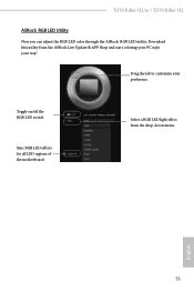
...RGB LED strip (12V/G/R/B), with a maximum power rating of 3A (12V) and length within 2 meters. 54 English Failure to motherboard components. 1. Please note that the RGB LED strips do so may be damaged. 2. Never install the RGB LED cable in ...schemes and patterns, including Static, Breathing, Strobe, Cycling, Music, Wave and more. 3.4 ASRock RGB LED ASRock RGB LED is a lighting control utility specifically designed for unique individuals with sophisticated tastes to the RGB LED Headers (RGB_LED1, RGB_LED2) on the motherboard. 1 B 12V G R RGB_LED2 1 12V G R B RGB_LED1 1 12V G ...
...RGB LED strip (12V/G/R/B), with a maximum power rating of 3A (12V) and length within 2 meters. 54 English Failure to motherboard components. 1. Please note that the RGB LED strips do so may be damaged. 2. Never install the RGB LED cable in ...schemes and patterns, including Static, Breathing, Strobe, Cycling, Music, Wave and more. 3.4 ASRock RGB LED ASRock RGB LED is a lighting control utility specifically designed for unique individuals with sophisticated tastes to the RGB LED Headers (RGB_LED1, RGB_LED2) on the motherboard. 1 B 12V G R RGB_LED2 1 12V G R B RGB_LED1 1 12V G ...
User Manual
Page 61
English 55 Toggle on/off the RGB LED switch Sync RGB LED effects for all LED regions of the motherboard Select a RGB LED light effect from the ASRock Live Update & APP Shop and start coloring your PC style your preference. Download this utility from the drop-down menu. X370 Killer SLI/ac / X370 Killer SLI ASRock RGB LED Utility Now you can adjust the RGB LED color through the ASRock RGB LED utility. Drag the tab to customize your way!
English 55 Toggle on/off the RGB LED switch Sync RGB LED effects for all LED regions of the motherboard Select a RGB LED light effect from the ASRock Live Update & APP Shop and start coloring your PC style your preference. Download this utility from the drop-down menu. X370 Killer SLI/ac / X370 Killer SLI ASRock RGB LED Utility Now you can adjust the RGB LED color through the ASRock RGB LED utility. Drag the tab to customize your way!


