User Manual
Page 4
Contents Chapter 1 Introduction 1 1.1 Package Contents 1 1.2 Specifications 2 1.3 Motherboard Layout 7 1.4 I/O Panel 9 1.5 WiFi-802.11ac Module and ASRock WiFi 2.4/5 GHz Antenna (for X370 Killer SLI/ac only) 11 Chapter 2 Installation 13 2.1 Installing the CPU 14 2.2 Installing the CPU Fan and Heatsink 16 2.3 Installing Memory Modules (DIMM) 25 2.4 Expansion Slots (PCI Express ...
Contents Chapter 1 Introduction 1 1.1 Package Contents 1 1.2 Specifications 2 1.3 Motherboard Layout 7 1.4 I/O Panel 9 1.5 WiFi-802.11ac Module and ASRock WiFi 2.4/5 GHz Antenna (for X370 Killer SLI/ac only) 11 Chapter 2 Installation 13 2.1 Installing the CPU 14 2.2 Installing the CPU Fan and Heatsink 16 2.3 Installing Memory Modules (DIMM) 25 2.4 Expansion Slots (PCI Express ...

User Manual
Page 7
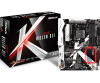
... notice. ASRock website http://www.asrock.com. 1.1 Package Contents • ASRock X370 Killer SLI/ac / X370 Killer SLI Motherboard (ATX Form Factor) • ASRock X370 Killer SLI/ac / X370 Killer SLI Quick Installation Guide • ASRock X370 Killer SLI/ac / X370 Killer SLI Support CD • 1 x I/O Panel Shield • 2 x Serial ATA (SATA) Data Cables (Optional) • 1 x ASRock SLI_HB_Bridge_2S Card (Optional) • 3 x Screws for M.2 Socket (Optional) (for X370 Killer SLI only) • 2 x Screws for M.2 Socket (Optional) (for X370 Killer SLI/ac only) • 2 x ASRock WiFi...
... notice. ASRock website http://www.asrock.com. 1.1 Package Contents • ASRock X370 Killer SLI/ac / X370 Killer SLI Motherboard (ATX Form Factor) • ASRock X370 Killer SLI/ac / X370 Killer SLI Quick Installation Guide • ASRock X370 Killer SLI/ac / X370 Killer SLI Support CD • 1 x I/O Panel Shield • 2 x Serial ATA (SATA) Data Cables (Optional) • 1 x ASRock SLI_HB_Bridge_2S Card (Optional) • 3 x Screws for M.2 Socket (Optional) (for X370 Killer SLI only) • 2 x Screws for M.2 Socket (Optional) (for X370 Killer SLI/ac only) • 2 x ASRock WiFi...
User Manual
Page 17
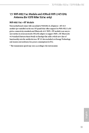
X370 Killer SLI/ac / X370 Killer SLI 1.5 WiFi-802.11ac Module and ASRock WiFi 2.4/5 GHz Antenna (for X370 Killer SLI/ac only) WiFi-802.11ac + BT Module This motherboard comes with an exclusive WiFi 802.11 a/b/g/n/ac + BT v4.0 module (pre-installed on the rear I/O panel) that adds a whole new class of functionality into the mobile devices. BT 4.0 also includes Low Energy ...
X370 Killer SLI/ac / X370 Killer SLI 1.5 WiFi-802.11ac Module and ASRock WiFi 2.4/5 GHz Antenna (for X370 Killer SLI/ac only) WiFi-802.11ac + BT Module This motherboard comes with an exclusive WiFi 802.11 a/b/g/n/ac + BT v4.0 module (pre-installed on the rear I/O panel) that adds a whole new class of functionality into the mobile devices. BT 4.0 also includes Low Energy ...
User Manual
Page 19
...the components. • When placing screws to secure the motherboard to the motherboard's components, NEVER place your motherboard directly on a grounded anti-static pad or in the bag that the motherboard fits into it. Also remember to use a grounded wrist... Whenever you install the motherboard, study the configuration of the following precautions before installing or removing the motherboard. Doing so may cause physical injuries to you install motherboard components or change any components, place them on a carpet. X370 Killer SLI/ac / X370 Killer SLI Chapter 2 Installation This ...
...the components. • When placing screws to secure the motherboard to the motherboard's components, NEVER place your motherboard directly on a grounded anti-static pad or in the bag that the motherboard fits into it. Also remember to use a grounded wrist... Whenever you install the motherboard, study the configuration of the following precautions before installing or removing the motherboard. Doing so may cause physical injuries to you install motherboard components or change any components, place them on a carpet. X370 Killer SLI/ac / X370 Killer SLI Chapter 2 Installation This ...
User Manual
Page 31
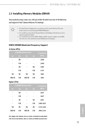
... 2667 - SR - For dual channel configuration, you always need to install a DDR, DDR2 or DDR3 memory module into a DDR4 slot; otherwise, this motherboard and DIMM may be damaged. DR - - 2667 - DR SR SR SR SR SR/DR DR SR/DR DR 2400 2400 2400 2133 1866 1866 Ryzen..., 1Rx4 or 1Rx8 on DIMM module label DR: Dual rank DIMM, 2Rx4 or 2Rx8 on DIMM module label 25 English SR - X370 Killer SLI/ac / X370 Killer SLI 2.3 Installing Memory Modules (DIMM) This motherboard provides four 288-pin DDR4 (Double Data Rate 4) DIMM slots, and supports Dual Channel Memory Technology. 1.
... 2667 - SR - For dual channel configuration, you always need to install a DDR, DDR2 or DDR3 memory module into a DDR4 slot; otherwise, this motherboard and DIMM may be damaged. DR - - 2667 - DR SR SR SR SR SR/DR DR SR/DR DR 2400 2400 2400 2133 1866 1866 Ryzen..., 1Rx4 or 1Rx8 on DIMM module label DR: Dual rank DIMM, 2Rx4 or 2Rx8 on DIMM module label 25 English SR - X370 Killer SLI/ac / X370 Killer SLI 2.3 Installing Memory Modules (DIMM) This motherboard provides four 288-pin DDR4 (Double Data Rate 4) DIMM slots, and supports Dual Channel Memory Technology. 1.
User Manual
Page 33
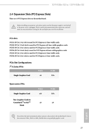
... PCIE4 N/A x8 English For a better thermal environment, please connect a chassis fan to the motherboard's chassis fan connector (CHA_FAN1 or CHA_FAN2) when using multiple graphics cards. 27 X370 Killer SLI/ac / X370 Killer SLI 2.4 Expansion Slots (PCI Express Slots) There are 6 PCI Express slots on the motherboard. PCIe slots: PCIE1 (PCIe 2.0 x1 slot) is used for PCI Express x1 lane...
... PCIE4 N/A x8 English For a better thermal environment, please connect a chassis fan to the motherboard's chassis fan connector (CHA_FAN1 or CHA_FAN2) when using multiple graphics cards. 27 X370 Killer SLI/ac / X370 Killer SLI 2.4 Expansion Slots (PCI Express Slots) There are 6 PCI Express slots on the motherboard. PCIe slots: PCIE1 (PCIe 2.0 x1 slot) is used for PCI Express x1 lane...
User Manual
Page 35
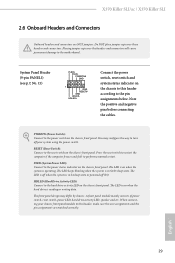
...panel. A front panel module mainly consists of power switch, reset switch, power LED, hard drive activity LED, speaker and etc. X370 Killer SLI/ac / X370 Killer SLI 2.6 Onboard Headers and Connectors Onboard headers and connectors are matched correctly. Note the positive and negative pins before connecting the cables. You...S3 sleep state. The LED is off (S5). HDLED (Hard Drive Activity LED): Connect to this header according to the motherboard. When connecting your system using the power switch. Do NOT place jumper caps over the headers and connectors will cause permanent ...
...panel. A front panel module mainly consists of power switch, reset switch, power LED, hard drive activity LED, speaker and etc. X370 Killer SLI/ac / X370 Killer SLI 2.6 Onboard Headers and Connectors Onboard headers and connectors are matched correctly. Note the positive and negative pins before connecting the cables. You...S3 sleep state. The LED is off (S5). HDLED (Hard Drive Activity LED): Connect to this header according to the motherboard. When connecting your system using the power switch. Do NOT place jumper caps over the headers and connectors will cause permanent ...
User Manual
Page 37
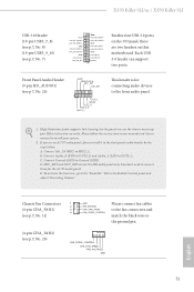
...and chassis manual to the front audio panel. 1. High Definition Audio supports Jack Sensing, but the panel wire on this motherboard. MIC_RET and OUT_RET are two headers on the chassis must support HDA to the ground pin. 4 3 21 FAN_SPEED_CONTROL ... and 4 FAN_SPEED_CONTROL match the black wire to function correctly. Please follow the instructions in the Realtek Control panel and adjust "Recording Volume". X370 Killer SLI/ac / X370 Killer SLI USB 3.0 Header (19-pin USB3_7_8) (see p.7, No. 8) (19-pin USB3_9_10) (see p.7, No. 7) Vbus IntA_PA_SSRXIntA_PA_SSRX+ GND ...
...and chassis manual to the front audio panel. 1. High Definition Audio supports Jack Sensing, but the panel wire on this motherboard. MIC_RET and OUT_RET are two headers on the chassis must support HDA to the ground pin. 4 3 21 FAN_SPEED_CONTROL ... and 4 FAN_SPEED_CONTROL match the black wire to function correctly. Please follow the instructions in the Realtek Control panel and adjust "Recording Volume". X370 Killer SLI/ac / X370 Killer SLI USB 3.0 Header (19-pin USB3_7_8) (see p.7, No. 8) (19-pin USB3_9_10) (see p.7, No. 7) Vbus IntA_PA_SSRXIntA_PA_SSRX+ GND ...
User Manual
Page 43
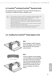
X370 Killer SLI/ac / X370 Killer SLI 2.8 CrossFireXTM and Quad CrossFireXTM Operation Guide This motherboard supports CrossFireXTM and Quad CrossFireXTM that your power supply unit (PSU) can provide at least the minimum power your system requires. It is ... cards while in CrossFireXTM mode. 5. Please refer to PCIE3 slot. Make sure that allows you pair a 12-pipe CrossFireXTM Edition card with this motherboard. Different CrossFireXTM cards may require different methods to use identical CrossFireXTM-ready graphics cards that are properly seated on the slots. Please refer to the...
X370 Killer SLI/ac / X370 Killer SLI 2.8 CrossFireXTM and Quad CrossFireXTM Operation Guide This motherboard supports CrossFireXTM and Quad CrossFireXTM that your power supply unit (PSU) can provide at least the minimum power your system requires. It is ... cards while in CrossFireXTM mode. 5. Please refer to PCIE3 slot. Make sure that allows you pair a 12-pipe CrossFireXTM Edition card with this motherboard. Different CrossFireXTM cards may require different methods to use identical CrossFireXTM-ready graphics cards that are properly seated on the slots. Please refer to the...
User Manual
Page 47
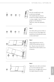
Otherwise, release the standoff by default. D C B A D C B A D C B A C B A D NUT2 NUT1 X370 Killer SLI/ac / X370 Killer SLI Step 3 Move the standoff based on the motherboard. Skip Step 3 and 4 and go straight to Step 5 if you are going to secure the module into place. Please be used. Please do not overtighten ...
Otherwise, release the standoff by default. D C B A D C B A D C B A C B A D NUT2 NUT1 X370 Killer SLI/ac / X370 Killer SLI Step 3 Move the standoff based on the motherboard. Skip Step 3 and 4 and go straight to Step 5 if you are going to secure the module into place. Please be used. Please do not overtighten ...

User Manual
Page 61
Download this utility from the drop-down menu. English 55 Drag the tab to customize your way! Toggle on/off the RGB LED switch Sync RGB LED effects for all LED regions of the motherboard Select a RGB LED light effect from the ASRock Live Update & APP Shop and start coloring your PC style your preference. X370 Killer SLI/ac / X370 Killer SLI ASRock RGB LED Utility Now you can adjust the RGB LED color through the ASRock RGB LED utility.
Download this utility from the drop-down menu. English 55 Drag the tab to customize your way! Toggle on/off the RGB LED switch Sync RGB LED effects for all LED regions of the motherboard Select a RGB LED light effect from the ASRock Live Update & APP Shop and start coloring your PC style your preference. X370 Killer SLI/ac / X370 Killer SLI ASRock RGB LED Utility Now you can adjust the RGB LED color through the ASRock RGB LED utility.

User Manual
Page 77
X370 Killer SLI/ac / X370 Killer SLI 4.6 Hardware Health Event Monitoring Screen This section allows you to set 5 CPU temperatures and assign a respective fan speed for each temperature. CPU Optional Fan Temp ... mode for CPU Optional fan, or choose Customize to monitor the status of the hardware on your system, including the parameters of the CPU temperature, motherboard temperature, fan speed and voltage.
X370 Killer SLI/ac / X370 Killer SLI 4.6 Hardware Health Event Monitoring Screen This section allows you to set 5 CPU temperatures and assign a respective fan speed for each temperature. CPU Optional Fan Temp ... mode for CPU Optional fan, or choose Customize to monitor the status of the hardware on your system, including the parameters of the CPU temperature, motherboard temperature, fan speed and voltage.
Quick Installation Guide
Page 7
...; ASRock X370 Killer SLI/ac / X370 Killer SLI Motherboard (ATX Form Factor) • ASRock X370 Killer SLI/ac / X370 Killer SLI Quick Installation Guide • ASRock X370 Killer SLI/ac / X370 Killer SLI Support CD • 1 x I/O Panel Shield • 4 x Serial ATA (SATA) Data Cables (Optional) • 1 x ASRock SLI_HB_Bridge_2S Card (Optional) • 3 x Screws for M.2 Socket (Optional) (for X370 Killer SLI only) • 2 x Screws for M.2 Socket (Optional) (for X370 Killer SLI/ac only) • 2 x ASRock WiFi 2.4/5 GHz Antennas (Optional) (for purchasing ASRock X370 Killer SLI/ac / X370...
...; ASRock X370 Killer SLI/ac / X370 Killer SLI Motherboard (ATX Form Factor) • ASRock X370 Killer SLI/ac / X370 Killer SLI Quick Installation Guide • ASRock X370 Killer SLI/ac / X370 Killer SLI Support CD • 1 x I/O Panel Shield • 4 x Serial ATA (SATA) Data Cables (Optional) • 1 x ASRock SLI_HB_Bridge_2S Card (Optional) • 3 x Screws for M.2 Socket (Optional) (for X370 Killer SLI only) • 2 x Screws for M.2 Socket (Optional) (for X370 Killer SLI/ac only) • 2 x ASRock WiFi 2.4/5 GHz Antennas (Optional) (for purchasing ASRock X370 Killer SLI/ac / X370...
Quick Installation Guide
Page 13
... Technology and ensures extraordinary low power consumption for WiFi 802.11 a/b/ g/n/ac connectivity standards and Bluetooth v4.0. X370 Killer SLI/ac / X370 Killer SLI 1.3 WiFi-802.11ac Module and ASRock WiFi 2.4/5 GHz Antenna (for X370 Killer SLI/ac only) WiFi-802.11ac + BT Module This motherboard comes with an exclusive WiFi 802.11 a/b/g/n/ac + BT v4.0 module (pre-installed on the rear I/O panel) that adds...
... Technology and ensures extraordinary low power consumption for WiFi 802.11 a/b/ g/n/ac connectivity standards and Bluetooth v4.0. X370 Killer SLI/ac / X370 Killer SLI 1.3 WiFi-802.11ac Module and ASRock WiFi 2.4/5 GHz Antenna (for X370 Killer SLI/ac only) WiFi-802.11ac + BT Module This motherboard comes with an exclusive WiFi 802.11 a/b/g/n/ac + BT v4.0 module (pre-installed on the rear I/O panel) that adds...

Quick Installation Guide
Page 15
... the screws! Doing so may cause physical injuries to you and damages to motherboard components. • In order to avoid damage from static electricity to the motherboard's components, NEVER place your chassis to ensure that comes with the components. ...motherboard. Pre-installation Precautions Take note of your motherboard directly on a grounded anti-static pad or in the bag that the motherboard fits into it. Also remember to unplug the power cord before you install motherboard components or change any components, place them on a carpet. X370 Killer SLI/ac / X370 Killer SLI...
... the screws! Doing so may cause physical injuries to you and damages to motherboard components. • In order to avoid damage from static electricity to the motherboard's components, NEVER place your chassis to ensure that comes with the components. ...motherboard. Pre-installation Precautions Take note of your motherboard directly on a grounded anti-static pad or in the bag that the motherboard fits into it. Also remember to unplug the power cord before you install motherboard components or change any components, place them on a carpet. X370 Killer SLI/ac / X370 Killer SLI...

Quick Installation Guide
Page 27
...For dual channel configuration, you always need to activate Dual Channel Memory Technology with only one or three memory module installed. 3. otherwise, this motherboard and DIMM may be damaged. SR - - - SR - DR - It is not allowed to install a DDR, DDR2 or DDR3 ...DR: Dual rank DIMM, 2Rx4 or 2Rx8 on DIMM module label 25 English DR - DR - - - SR - X370 Killer SLI/ac / X370 Killer SLI 2.3 Installing Memory Modules (DIMM) This motherboard provides four 288-pin DDR4 (Double Data Rate 4) DIMM slots, and supports Dual Channel Memory Technology. 1. It is...
...For dual channel configuration, you always need to activate Dual Channel Memory Technology with only one or three memory module installed. 3. otherwise, this motherboard and DIMM may be damaged. SR - - - SR - DR - It is not allowed to install a DDR, DDR2 or DDR3 ...DR: Dual rank DIMM, 2Rx4 or 2Rx8 on DIMM module label 25 English DR - DR - - - SR - X370 Killer SLI/ac / X370 Killer SLI 2.3 Installing Memory Modules (DIMM) This motherboard provides four 288-pin DDR4 (Double Data Rate 4) DIMM slots, and supports Dual Channel Memory Technology. 1. It is...

Quick Installation Guide
Page 29
... the power supply is switched off or the power cord is used for PCI Express x1 lane width cards. X370 Killer SLI/ac / X370 Killer SLI 2.4 Expansion Slots (PCI Express Slots) There are 6 PCI Express slots on the motherboard. Before installing an expansion card, please make necessary hardware settings for PCI Express x1 lane width cards. PCIe slots...
... the power supply is switched off or the power cord is used for PCI Express x1 lane width cards. X370 Killer SLI/ac / X370 Killer SLI 2.4 Expansion Slots (PCI Express Slots) There are 6 PCI Express slots on the motherboard. Before installing an expansion card, please make necessary hardware settings for PCI Express x1 lane width cards. PCIe slots...

Quick Installation Guide
Page 31
... reset switch on when the hard drive is in S1/S3 sleep state. HDLED (Hard Drive Activity LED): Connect to the motherboard. Placing jumper caps over these headers and connectors. X370 Killer SLI/ac / X370 Killer SLI 2.6 Onboard Headers and Connectors Onboard headers and connectors are matched correctly. Do NOT place jumper caps over the headers and connectors...
... reset switch on when the hard drive is in S1/S3 sleep state. HDLED (Hard Drive Activity LED): Connect to the motherboard. Placing jumper caps over these headers and connectors. X370 Killer SLI/ac / X370 Killer SLI 2.6 Onboard Headers and Connectors Onboard headers and connectors are matched correctly. Do NOT place jumper caps over the headers and connectors...

Quick Installation Guide
Page 33
... four USB 3.0 ports on this motherboard. Connect Mic_IN (MIC) to Ground (GND). C. To activate the front mic, go to install your system. 2. MIC_RET and OUT_RET are two headers on the I/O panel, there are for connecting audio devices to the front audio panel. 1. X370 Killer SLI/ac / X370 Killer SLI USB 3.0 Header (19-pin USB3_7_8... J_SENSE OUT2_R MIC2_R MIC2_L This header is for the HD audio panel only. If you use an AC'97 audio panel, please install it to connect them for the AC'97 audio panel. Each USB 3.0 header can support two ports. You don't need to the front...
... four USB 3.0 ports on this motherboard. Connect Mic_IN (MIC) to Ground (GND). C. To activate the front mic, go to install your system. 2. MIC_RET and OUT_RET are two headers on the I/O panel, there are for connecting audio devices to the front audio panel. 1. X370 Killer SLI/ac / X370 Killer SLI USB 3.0 Header (19-pin USB3_7_8... J_SENSE OUT2_R MIC2_R MIC2_L This header is for the HD audio panel only. If you use an AC'97 audio panel, please install it to connect them for the AC'97 audio panel. Each USB 3.0 header can support two ports. You don't need to the front...

Quick Installation Guide
Page 37
... length. Otherwise, release the standoff by default. Hand tighten the standoff into place. The standoff is placed at the nut location D by hand. D C B A D C B A D C B A C B A D NUT2 NUT1 X370 Killer SLI/ac / X370 Killer SLI Step 3 Move the standoff based on the motherboard. Step 5 Align and gently insert the M.2 (NGFF) SSD module into the M.2 slot.
... length. Otherwise, release the standoff by default. Hand tighten the standoff into place. The standoff is placed at the nut location D by hand. D C B A D C B A D C B A C B A D NUT2 NUT1 X370 Killer SLI/ac / X370 Killer SLI Step 3 Move the standoff based on the motherboard. Step 5 Align and gently insert the M.2 (NGFF) SSD module into the M.2 slot.


