User Manual
Page 6
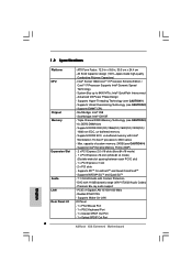
...; X58 - Supports DDR3 2000(OC)/1866(OC)/1600(OC)/1333(OC)/1066 non-ECC, un-buffered memory - capacity of system memory: 24GB (see CAUTION 3) - 6 x DDR3 DIMM slots - PCIE x1 Gigabit LAN 10/100/1000 Mb/s - System Bus up to 6400 MT/s; Max. Supports ATITM CrossFireXTM and Quad CrossFireXTM - Intel® Socket 1366 CoreTM...
...; X58 - Supports DDR3 2000(OC)/1866(OC)/1600(OC)/1333(OC)/1066 non-ECC, un-buffered memory - capacity of system memory: 24GB (see CAUTION 3) - 6 x DDR3 DIMM slots - PCIE x1 Gigabit LAN 10/100/1000 Mb/s - System Bus up to 6400 MT/s; Max. Supports ATITM CrossFireXTM and Quad CrossFireXTM - Intel® Socket 1366 CoreTM...

User Manual
Page 13
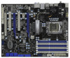
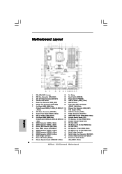
...CODEC Super I/O CI1 1 IR1 1 HDMI_SPDIF1 1 FLOPPY1 NEC USB 3.0 SATA3 6Gb/s IDE1 PCIE1 QPI 6.4GT/s PCIE2 PCI Express 2.0 PCI1 X58 Extreme3 8Mb BIOS 1394a CMOS Battery CLRCMOS1 1 PCIE3 ErP/EuP Ready PCI2 VIA VT6308S Intel ICH10R RoHS PCIE4 COM1 1 1 TPM1 FRONT_1394 CHA_FAN1 1 USB6_7...22 Dr. Debug 2 CPU Fan Connector (CPU_FAN1) 23 Reset Switch (RSTBTN) 3 ATX 12V Power Connector (ATX12V1) 24 Power Switch (PWRBTN) 4 1366-Pin CPU Socket 25 USB 2.0 Header (USB6_7, Blue) 5 Power Fan Connector (PWR_FAN1) 26 8Mb SPI Flash 6 Chassis Fan Connector (CHA_FAN2) 27 Front Panel IEEE...
...CODEC Super I/O CI1 1 IR1 1 HDMI_SPDIF1 1 FLOPPY1 NEC USB 3.0 SATA3 6Gb/s IDE1 PCIE1 QPI 6.4GT/s PCIE2 PCI Express 2.0 PCI1 X58 Extreme3 8Mb BIOS 1394a CMOS Battery CLRCMOS1 1 PCIE3 ErP/EuP Ready PCI2 VIA VT6308S Intel ICH10R RoHS PCIE4 COM1 1 1 TPM1 FRONT_1394 CHA_FAN1 1 USB6_7...22 Dr. Debug 2 CPU Fan Connector (CPU_FAN1) 23 Reset Switch (RSTBTN) 3 ATX 12V Power Connector (ATX12V1) 24 Power Switch (PWRBTN) 4 1366-Pin CPU Socket 25 USB 2.0 Header (USB6_7, Blue) 5 Power Fan Connector (PWR_FAN1) 26 8Mb SPI Flash 6 Chassis Fan Connector (CHA_FAN2) 27 Front Panel IEEE...
User Manual
Page 17
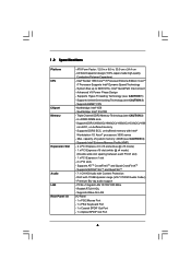
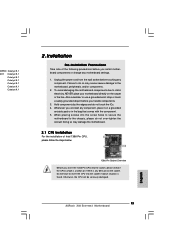
...to fully open position at approximately 135 degrees. Step 1-3. It is recommended to use the cap tab to insert the CPU into the socket, please check if the CPU surface is unclean or if there is found. Rotate the load plate to clear retention tab. This ... and Place Cap). 1. Open the socket: Step 1-1. Step 1-2. Step 2. 2.3 CPU Installation For the installation of Intel 1366-Pin CPU, please follow the steps below. Load Plate Contact Array Socket Body Load Lever 1366-Pin Socket Overview Before you insert the 1366-Pin CPU into the socket if above situation is any bent pin...
...to fully open position at approximately 135 degrees. Step 1-3. It is recommended to use the cap tab to insert the CPU into the socket, please check if the CPU surface is unclean or if there is found. Rotate the load plate to clear retention tab. This ... and Place Cap). 1. Open the socket: Step 1-1. Step 1-2. Step 2. 2.3 CPU Installation For the installation of Intel 1366-Pin CPU, please follow the steps below. Load Plate Contact Array Socket Body Load Lever 1366-Pin Socket Overview Before you insert the 1366-Pin CPU into the socket if above situation is any bent pin...
User Manual
Page 18
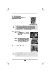
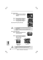
...two alignment keys of the socket. orientation key notch Pin1 Pin1 alignment key orientation key notch 1366-Pin CPU alignment key 1366-Pin Socket For proper inserting, please ensure to the orient keys. Step 3-3. Step 4. Carefully place the CPU into the socket by the edges where are... lever. Secure load lever with black lines. Step 4-2. Insert the 1366-Pin CPU: Step 3-1. Step 3-4. black line black line Step 3. Close the socket: Step 4-1. Step 4-3. Verify that the CPU is within the socket and properly mated to match the two orientation key notches of load lever...
...two alignment keys of the socket. orientation key notch Pin1 Pin1 alignment key orientation key notch 1366-Pin CPU alignment key 1366-Pin Socket For proper inserting, please ensure to the orient keys. Step 3-3. Step 4. Carefully place the CPU into the socket by the edges where are... lever. Secure load lever with black lines. Step 4-2. Insert the 1366-Pin CPU: Step 3-1. Step 3-4. black line black line Step 3. Close the socket: Step 4-1. Step 4-3. Verify that the CPU is within the socket and properly mated to match the two orientation key notches of load lever...
User Manual
Page 19
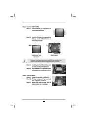
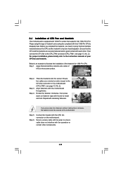
Ensure that supports Intel 1366-Pin CPU. Step 4. Align fasteners with remaining fasteners. Repeat with the motherboard throughholes. Step 5. Secure excess cable with tie-wrap to ensure cable does not interfere with the CPU fan connector on the socket surface. Please adopt the type of IHS ...page 13, No. 2). Below is equipped with each other components. 19 Ensure fan cables are securely fastened and in good contact with 1366-Pin socket that the CPU and the heatsink are oriented on side closest to the CPU fan connector on the motherboard. Step 1. Step 3. Place...
Ensure that supports Intel 1366-Pin CPU. Step 4. Align fasteners with remaining fasteners. Repeat with the motherboard throughholes. Step 5. Secure excess cable with tie-wrap to ensure cable does not interfere with the CPU fan connector on the socket surface. Please adopt the type of IHS ...page 13, No. 2). Below is equipped with each other components. 19 Ensure fan cables are securely fastened and in good contact with 1366-Pin socket that the CPU and the heatsink are oriented on side closest to the CPU fan connector on the motherboard. Step 1. Step 3. Place...
Quick Installation Guide
Page 2
...22 Dr. Debug 2 CPU Fan Connector (CPU_FAN1) 23 Reset Switch (RSTBTN) 3 ATX 12V Power Connector (ATX12V1) 24 Power Switch (PWRBTN) 4 1366-Pin CPU Socket 25 USB 2.0 Header (USB6_7, Blue) 5 Power Fan Connector (PWR_FAN1) 26 8Mb SPI Flash 6 Chassis Fan Connector (CHA_FAN2) 27 Front Panel IEEE...CD1 (Black) 20 Power LED Header (PLED1) 44 Front Panel Audio Header 21 Chassis Speaker Header (SPEAKER 1, White) (HD_AUDIO1, White) 2 ASRock X58 Extreme3 Motherboard English White) 29 TPM Header (TPM1) 8 ATX Power Connector (ATXPWR1) 30 COM Port Header (COM1) 9 System Panel Header (PANEL1, ...
...22 Dr. Debug 2 CPU Fan Connector (CPU_FAN1) 23 Reset Switch (RSTBTN) 3 ATX 12V Power Connector (ATX12V1) 24 Power Switch (PWRBTN) 4 1366-Pin CPU Socket 25 USB 2.0 Header (USB6_7, Blue) 5 Power Fan Connector (PWR_FAN1) 26 8Mb SPI Flash 6 Chassis Fan Connector (CHA_FAN2) 27 Front Panel IEEE...CD1 (Black) 20 Power LED Header (PLED1) 44 Front Panel Audio Header 21 Chassis Speaker Header (SPEAKER 1, White) (HD_AUDIO1, White) 2 ASRock X58 Extreme3 Motherboard English White) 29 TPM Header (TPM1) 8 ATX Power Connector (ATXPWR1) 30 COM Port Header (COM1) 9 System Panel Header (PANEL1, ...
Quick Installation Guide
Page 6
... Panel - 1 x PS/2 Mouse Port - 1 x PS/2 Keyboard Port - 1 x Coaxial SPDIF Out Port - 1 x Optical SPDIF Out Port 6 ASRock X58 Extreme3 Motherboard English ATX Form Factor: 12.0-in x 9.6-in, 30.5 cm x 24.4 cm - System Bus up to 6400 MT/s; Southbridge: Intel® ICH10R - Supports...1066 non-ECC, un-buffered memory - All Solid Capacitor design (100% Japan-made high-quality Conductive Polymer Capacitors) - Intel® Socket 1366 CoreTM i7 Processor Extreme Edition / CoreTM i7 Processor Supports Intel® Dynamic Speed Technology - Supports Hyper-Threading Technology (see CAUTION 3) ...
... Panel - 1 x PS/2 Mouse Port - 1 x PS/2 Keyboard Port - 1 x Coaxial SPDIF Out Port - 1 x Optical SPDIF Out Port 6 ASRock X58 Extreme3 Motherboard English ATX Form Factor: 12.0-in x 9.6-in, 30.5 cm x 24.4 cm - System Bus up to 6400 MT/s; Southbridge: Intel® ICH10R - Supports...1066 non-ECC, un-buffered memory - All Solid Capacitor design (100% Japan-made high-quality Conductive Polymer Capacitors) - Intel® Socket 1366 CoreTM i7 Processor Extreme Edition / CoreTM i7 Processor Supports Intel® Dynamic Speed Technology - Supports Hyper-Threading Technology (see CAUTION 3) ...
Quick Installation Guide
Page 13
... if there is found. English 13 ASRock X58 Extreme3 Motherboard Hold components by the edges and do not over-tighten the screws! 00PRO Catalyst 9.1 00XT Catalyst 9.1 Catalyst 9.1 Catalyst 9.1 Catalyst 9.1 Catalyst 9.1 Catalyst 9.1 2. Installation Pre-installation Precautions Take note of Intel 1366-Pin CPU, please follow the steps below. 1366-Pin Socket Overview Before you uninstall any bent...
... if there is found. English 13 ASRock X58 Extreme3 Motherboard Hold components by the edges and do not over-tighten the screws! 00PRO Catalyst 9.1 00XT Catalyst 9.1 Catalyst 9.1 Catalyst 9.1 Catalyst 9.1 Catalyst 9.1 Catalyst 9.1 2. Installation Pre-installation Precautions Take note of Intel 1366-Pin CPU, please follow the steps below. 1366-Pin Socket Overview Before you uninstall any bent...
Quick Installation Guide
Page 14
... at approximately 135 degrees. black line black line English 1. Step 3. Orient the CPU with the two alignment keys of the socket. 14 ASRock X58 Extreme3 Motherboard Locate Pin1 and the two orientation key notches. Step 1. Rotate the load plate to clear retention tab. This cap must...on the hook to fully open position at approximately 100 degrees. orientation key notch Pin1 Pin1 alignment key orientation key notch 1366-Pin CPU alignment key 1366-Pin Socket For proper inserting, please ensure to handle and avoid kicking off the PnP cap. 2. Step 1-2. Step 1-3. Remove...
... at approximately 135 degrees. black line black line English 1. Step 3. Orient the CPU with the two alignment keys of the socket. 14 ASRock X58 Extreme3 Motherboard Locate Pin1 and the two orientation key notches. Step 1. Rotate the load plate to clear retention tab. This cap must...on the hook to fully open position at approximately 100 degrees. orientation key notch Pin1 Pin1 alignment key orientation key notch 1366-Pin CPU alignment key 1366-Pin Socket For proper inserting, please ensure to handle and avoid kicking off the PnP cap. 2. Step 1-2. Step 1-3. Remove...
Quick Installation Guide
Page 15
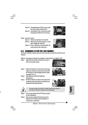
... heatsink. Connect fan header with fan operation or contact other components. 15 ASRock X58 Extreme3 Motherboard English Rotate the load plate onto the IHS. Step 4-2. Step 1. Place the heatsink onto the socket. If you press down the fasteners without rotating them clockwise, the heatsink... on the motherboard (CPU_FAN1, see page 2, No. 2). Step 4. While pressing down on the socket surface. Step 4-3. Apply thermal interface material onto center of the heatsink for 1366-Pin CPU. Step 4. Step 6. Step 3. Align fasteners with thumb to the CPU fan connector on...
... heatsink. Connect fan header with fan operation or contact other components. 15 ASRock X58 Extreme3 Motherboard English Rotate the load plate onto the IHS. Step 4-2. Step 1. Place the heatsink onto the socket. If you press down the fasteners without rotating them clockwise, the heatsink... on the motherboard (CPU_FAN1, see page 2, No. 2). Step 4. While pressing down on the socket surface. Step 4-3. Apply thermal interface material onto center of the heatsink for 1366-Pin CPU. Step 4. Step 6. Step 3. Align fasteners with thumb to the CPU fan connector on...