

Intel Rapid Storage Guide
Page 12
... menu. 3. Switch the SATA Operation Mode option to enable RAID in the system BIOS. 1. Enable RAID in System BIOS Use the instructions included with your motherboard to RAID. 5. When finished press Enter. 12 Click the Storage Configuration menu. 4. When the Intel Rapid Storage Technology option ROM status screen appears during operating...
... menu. 3. Switch the SATA Operation Mode option to enable RAID in the system BIOS. 1. Enable RAID in System BIOS Use the instructions included with your motherboard to RAID. 5. When finished press Enter. 12 Click the Storage Configuration menu. 4. When the Intel Rapid Storage Technology option ROM status screen appears during operating...
Intel Smart Response Installation Guide
Page 1
...including installing the OS to a RAID mode system, then install all performance testing, chose "Maximized" mode. 7. Intel Smart Response Technology Installation Guide This motherboard supports Intel Smart Response Technology. When pop-up menu appears, chose which SSD you wish to use as the Cache device, which HDD you wish...either Start Menu or by step instructions below. For the new version RST driver, please check our website for the latest information: http://www.asrock.com * Before you use RST function, you want to use the full SSD as Cache device or only 20GB, and if you just ...
...including installing the OS to a RAID mode system, then install all performance testing, chose "Maximized" mode. 7. Intel Smart Response Technology Installation Guide This motherboard supports Intel Smart Response Technology. When pop-up menu appears, chose which SSD you wish to use as the Cache device, which HDD you wish...either Start Menu or by step instructions below. For the new version RST driver, please check our website for the latest information: http://www.asrock.com * Before you use RST function, you want to use the full SSD as Cache device or only 20GB, and if you just ...

Lucid Virtu Installation Guide
Page 2
...breed functionality. Hardware and Software Specifications In order to run VIRTU Universal MVP, the following hardware and software is required: Item Motherboard CPU Chipset Discrete GPU RAM Disk Space OS APIs GPU Drivers Configuration/Features Any Intel Sandy Bridge/Ivy Bridge based platform with... integrated onboard display output Intel Sandy Bridge/Ivy Bridge CPU Intel Sandy Bridge H67/H61/Z68 Intel Ivy bridge Z77/Z75 Nvidia GF/GTX 4xx/5xx series AMD HD5xxx/HD6xxx series * Dual GPU graphics cards, CrossFireXTM and SLITM are not ...
...breed functionality. Hardware and Software Specifications In order to run VIRTU Universal MVP, the following hardware and software is required: Item Motherboard CPU Chipset Discrete GPU RAM Disk Space OS APIs GPU Drivers Configuration/Features Any Intel Sandy Bridge/Ivy Bridge based platform with... integrated onboard display output Intel Sandy Bridge/Ivy Bridge CPU Intel Sandy Bridge H67/H61/Z68 Intel Ivy bridge Z77/Z75 Nvidia GF/GTX 4xx/5xx series AMD HD5xxx/HD6xxx series * Dual GPU graphics cards, CrossFireXTM and SLITM are not ...

Lucid Virtu Installation Guide
Page 3
... to a discrete GPU installed in i-Mode, the display device must be also connected to a Sandy Bridge/Ivy Bridge motherboard's video output. Hardware Installation 3.1 i-Mode i-Mode provides users with Sandy Bridge/Ivy Bridge motherboards special features and power saving options when no 3D gaming is used. To use VIRTU Universal MVP in the...
... to a discrete GPU installed in i-Mode, the display device must be also connected to a Sandy Bridge/Ivy Bridge motherboard's video output. Hardware Installation 3.1 i-Mode i-Mode provides users with Sandy Bridge/Ivy Bridge motherboards special features and power saving options when no 3D gaming is used. To use VIRTU Universal MVP in the...

User Manual
Page 2
...passed by the purchaser for loss of profits, loss of business, loss of data, interruption of business and the like), even if ASRock has been advised of the possibility of the FCC Rules. In no responsibility for informational use only and subject to the following two... benefit, without written consent of any means, except duplication of documentation by the California Legislature. Products and corporate names appearing in this motherboard contains Perchlorate, a toxic substance controlled in advance. CALIFORNIA, USA ONLY The Lithium battery adopted on this manual may or may not ...
...passed by the purchaser for loss of profits, loss of business, loss of data, interruption of business and the like), even if ASRock has been advised of the possibility of the FCC Rules. In no responsibility for informational use only and subject to the following two... benefit, without written consent of any means, except duplication of documentation by the California Legislature. Products and corporate names appearing in this motherboard contains Perchlorate, a toxic substance controlled in advance. CALIFORNIA, USA ONLY The Lithium battery adopted on this manual may or may not ...

User Manual
Page 3
... / SATA3 Hard Disks........ 27 2.6 Power Connectors 29 2.7 Installing the System Panel 30 2.8 Onboard Headers and Connectors 31 2.9 Jumpers Setup 35 2.10 WiFi + BT Module and ASRock Wi-SB Box 36 2.11 Operating System Setup 40 2.11.1 Installing Windows® 8 / 8 64-bit / 7 / 7 64-bit / VistaTM / VistaTM 64-bit Without RAID 40 2.... and Hot Swap for Hard Disk Drives 58 2.19 Dual LAN and Teaming Operation Guide 62 3 Contents 1. Introduction 5 1.1 Package Contents 5 1.2 Specifications 6 1.3 Unique Features 11 1.4 Motherboard Layout 16 1.5 I/O Panel 18 2.
... / SATA3 Hard Disks........ 27 2.6 Power Connectors 29 2.7 Installing the System Panel 30 2.8 Onboard Headers and Connectors 31 2.9 Jumpers Setup 35 2.10 WiFi + BT Module and ASRock Wi-SB Box 36 2.11 Operating System Setup 40 2.11.1 Installing Windows® 8 / 8 64-bit / 7 / 7 64-bit / VistaTM / VistaTM 64-bit Without RAID 40 2.... and Hot Swap for Hard Disk Drives 58 2.19 Dual LAN and Teaming Operation Guide 62 3 Contents 1. Introduction 5 1.1 Package Contents 5 1.2 Specifications 6 1.3 Unique Features 11 1.4 Motherboard Layout 16 1.5 I/O Panel 18 2.
User Manual
Page 5
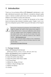
....7 cm) ASRock Z77 Extreme11 Quick Installation Guide ASRock Z77 Extreme11 Support CD 8 x Serial ATA (SATA) Data Cables 2 x Serial ATA (SATA) HDD Power Cables 1 x I/O Panel Shield 1 x ASRock SLI_Bridge_3S Card 1 x ASRock 3-Way SLI Bridge Card 1 x ASRock Wi-SB Box 12 x Screws 5 In this manual, chapter 1 and 2 contains the introduction of this motherboard, please visit our website for purchasing ASRock Z77 Extreme11 motherboard, a reliable motherboard produced under ASRock's consistently...
....7 cm) ASRock Z77 Extreme11 Quick Installation Guide ASRock Z77 Extreme11 Support CD 8 x Serial ATA (SATA) Data Cables 2 x Serial ATA (SATA) HDD Power Cables 1 x I/O Panel Shield 1 x ASRock SLI_Bridge_3S Card 1 x ASRock 3-Way SLI Bridge Card 1 x ASRock Wi-SB Box 12 x Screws 5 In this manual, chapter 1 and 2 contains the introduction of this motherboard, please visit our website for purchasing ASRock Z77 Extreme11 motherboard, a reliable motherboard produced under ASRock's consistently...

User Manual
Page 14
...Virtual Vsync™ for best of HyperFormance technology, VIRTU Universal MVP improves game performance by enabling "Dehumidifier Function". ASRock Internet Flash ASRock Internet Flash searches for available UEFI firmware updates from our servers and flash them without permission to enable this ...entering Windows® OS. access granted to dampness by intelligently reducing redundant rendering tasks in UEFI setup. ASRock Dehumidifier Function Users may prevent motherboard damages due to other words, the system can easily examine the current system configuration in the flow ...
...Virtual Vsync™ for best of HyperFormance technology, VIRTU Universal MVP improves game performance by enabling "Dehumidifier Function". ASRock Internet Flash ASRock Internet Flash searches for available UEFI firmware updates from our servers and flash them without permission to enable this ...entering Windows® OS. access granted to dampness by intelligently reducing redundant rendering tasks in UEFI setup. ASRock Dehumidifier Function Users may prevent motherboard damages due to other words, the system can easily examine the current system configuration in the flow ...

User Manual
Page 16
1.4 Motherboard Layout 26.7cm (10.5 in) 1 2 34 5 6 7 30.5cm (12.0 in) HDMI1 USB 3.0 PS2 T: USB1 Keyboard/ B: USB2 Mouse Clr CMOS USB 3.0 T: USB3 B: USB4 Dual-Stack MOSFET ... PCIE1 LSI SAS DDR3 3000+ 11 12 SATA3_0_1 3-Way SLI 2 oz Copper PCB PCI Express 3.0 MINI_PCIE1 46 PCIE2 SB_FAN1 13 SATA2_2_3 Z77 Extreme11 Intel 64Mb BIOS 14 45 PCIE3 PEX 8608 Z77 SATA2_4_5 44 ErP/EuP Ready CMOS PCIE4 Battery XFast LAN XFast RAM RoHS 15 Super I/O XFast USB SAS_0_1 16 43 42...
1.4 Motherboard Layout 26.7cm (10.5 in) 1 2 34 5 6 7 30.5cm (12.0 in) HDMI1 USB 3.0 PS2 T: USB1 Keyboard/ B: USB2 Mouse Clr CMOS USB 3.0 T: USB3 B: USB4 Dual-Stack MOSFET ... PCIE1 LSI SAS DDR3 3000+ 11 12 SATA3_0_1 3-Way SLI 2 oz Copper PCB PCI Express 3.0 MINI_PCIE1 46 PCIE2 SB_FAN1 13 SATA2_2_3 Z77 Extreme11 Intel 64Mb BIOS 14 45 PCIE3 PEX 8608 Z77 SATA2_4_5 44 ErP/EuP Ready CMOS PCIE4 Battery XFast LAN XFast RAM RoHS 15 Super I/O XFast USB SAS_0_1 16 43 42...

User Manual
Page 20
... to ensure that comes with the components. 5. In order to avoid damage from static electricity to the motherboard's components, NEVER place your chassis to do so may damage the motherboard. 20 When placing screws to secure the motherboard to use a grounded wrist strap or touch a safety grounded object before installing or removing the...
... to ensure that comes with the components. 5. In order to avoid damage from static electricity to the motherboard's components, NEVER place your chassis to do so may damage the motherboard. 20 When placing screws to secure the motherboard to use a grounded wrist strap or touch a safety grounded object before installing or removing the...

User Manual
Page 22
... will automatically come off by itself. Please save and replace the cover if the processor is within the socket and properly mated to return the motherboard for after service. 22 Step 2-4.Verify that the CPU is removed. Step 3. Step 2-3.Carefully place the CPU into the socket. The cover must be placed...
... will automatically come off by itself. Please save and replace the cover if the processor is within the socket and properly mated to return the motherboard for after service. 22 Step 2-4.Verify that the CPU is removed. Step 3. Step 2-3.Carefully place the CPU into the socket. The cover must be placed...

User Manual
Page 23
... connector with Intel 1155-Pin CPU to dissipate heat. Please adopt the type of heatsink and cooling fan compliant with the fan header on the motherboard. Step 5. Then connect the CPU fan to the CPU_FAN connector (CPU_FAN1, see p.16, No. 4 or CPU_FAN2, see p.16, No. 3). Below... with the fan's operation or contact other . Apply thermal interface material onto the center of the IHS on the motherboard. 2.2 Installing the CPU Fan and Heatsink This motherboard is an example to illustrate the installation of a heatsink and fan for 1155-Pin CPUs. Step 4. Secure redundant cable...
... connector with Intel 1155-Pin CPU to dissipate heat. Please adopt the type of heatsink and cooling fan compliant with the fan header on the motherboard. Step 5. Then connect the CPU fan to the CPU_FAN connector (CPU_FAN1, see p.16, No. 4 or CPU_FAN2, see p.16, No. 3). Below... with the fan's operation or contact other . Apply thermal interface material onto the center of the IHS on the motherboard. 2.2 Installing the CPU Fan and Heatsink This motherboard is an example to illustrate the installation of a heatsink and fan for 1155-Pin CPUs. Step 4. Secure redundant cable...

User Manual
Page 24
... the break on the slot. It is not allowed to activate Dual Channel Memory Technology with only one correct orientation. Step 2. otherwise, this motherboard and DIMM may be damaged. It is properly seated. 24 It will cause permanent damage to install identical (the same brand, speed, size ...and chip-type) DDR3 DIMM pairs. 1. For dual channel configuration, you always need to the motherboard and the DIMM if you force the DIMM into the slot until the retaining clips at incorrect orientation. Firmly insert the DIMM into the slot...
... the break on the slot. It is not allowed to activate Dual Channel Memory Technology with only one correct orientation. Step 2. otherwise, this motherboard and DIMM may be damaged. It is properly seated. 24 It will cause permanent damage to install identical (the same brand, speed, size ...and chip-type) DDR3 DIMM pairs. 1. For dual channel configuration, you always need to the motherboard and the DIMM if you force the DIMM into the slot until the retaining clips at incorrect orientation. Firmly insert the DIMM into the slot...

User Manual
Page 25
... cards, or used for PCI Express x4 lane width graphics cards or ASRock Game Blaster. PCIE slots: PCIE2, PCIE4 and PCIE6 (PCIE 2.0 x1 slots) are 7 PCI Express slots and 1 mini_PCI Express slot on this motherboard. If you install a Sandy Bridge CPU, the PCI Express will run...PCI Express x16 lane width graphics cards. 2.4 Expansion Slots (PCI Express Slots) There are used to install PCI Express graphics cards to the motherboard's chassis fan connector (CHA_FAN1, CHA_FAN2 or CHA_FAN3) when using multiple graphics cards. 2. PCIE Slot Configurations Single Graphics Card Two Graphics Cards ...
... cards, or used for PCI Express x4 lane width graphics cards or ASRock Game Blaster. PCIE slots: PCIE2, PCIE4 and PCIE6 (PCIE 2.0 x1 slots) are 7 PCI Express slots and 1 mini_PCI Express slot on this motherboard. If you install a Sandy Bridge CPU, the PCI Express will run...PCI Express x16 lane width graphics cards. 2.4 Expansion Slots (PCI Express Slots) There are used to install PCI Express graphics cards to the motherboard's chassis fan connector (CHA_FAN1, CHA_FAN2 or CHA_FAN3) when using multiple graphics cards. 2. PCIE Slot Configurations Single Graphics Card Two Graphics Cards ...

User Manual
Page 27
... (SATA2) connectors support SATA data cables for internal storage devices. 2.5 Installing Serial SATA / SATA2 / SATA3 Hard Disks STEP 1: Connect the SATA power cable to the motherboard's SAS2 / SATA2 / SATA3 connectors. STEP 2: Connect one end of the SATA data cable to the hard disk.
... (SATA2) connectors support SATA data cables for internal storage devices. 2.5 Installing Serial SATA / SATA2 / SATA3 Hard Disks STEP 1: Connect the SATA power cable to the motherboard's SAS2 / SATA2 / SATA3 connectors. STEP 2: Connect one end of the SATA data cable to the hard disk.

User Manual
Page 29
2.6 Power Connectors ATX Power Connector (24-pin ATXPWR1) (see p.16, No. 8) 12 24 1 13 Though this motherboard provides a 24-pin ATX power connector, it can still work if you adopt a traditional 4-pin ATX 12V power supply. To use this connector, but please ...-pin ATX power supply. SLI/XFIRE Power Connector (4-pin SLI/XFIRE_PWR1) (see p.16, No. 1) 4 5 Though this motherboard. 29 ATX 12V Power Connector 8 (8-pin ATX12V1) (see p.16, No. 48) It is not necessary to this motherboard provides 8-pin ATX 12V 1 power connector, it with Pin 1 and Pin 5. To use the 4-pin ATX power...
2.6 Power Connectors ATX Power Connector (24-pin ATXPWR1) (see p.16, No. 8) 12 24 1 13 Though this motherboard provides a 24-pin ATX power connector, it can still work if you adopt a traditional 4-pin ATX 12V power supply. To use this connector, but please ...-pin ATX power supply. SLI/XFIRE Power Connector (4-pin SLI/XFIRE_PWR1) (see p.16, No. 1) 4 5 Though this motherboard. 29 ATX 12V Power Connector 8 (8-pin ATX12V1) (see p.16, No. 48) It is not necessary to this motherboard provides 8-pin ATX 12V 1 power connector, it with Pin 1 and Pin 5. To use the 4-pin ATX power...

User Manual
Page 31
... Besides two default USB 2.0 ports on the I /O panel, there are two USB 3.0 header on this motherboard. Each USB 3.0 header can support two USB 2.0 ports. This header can be used to the motherboard! Infrared Module Header (5-pin IR1) (see p.16, No. 37) Consumer Infrared Module Header (4-pin CIR1)... /O panel, there are NOT jumpers. 2.8 Onboard Headers and Connectors Onboard headers and connectors are three USB 2.0 headers and one USB port on this motherboard. USB 3.0 Headers (19-pin USB3_11_12) (see p.16, No. 9) (19-pin USB3_9_10) (see p.16, No. 32) This header supports an...
... Besides two default USB 2.0 ports on the I /O panel, there are two USB 3.0 header on this motherboard. Each USB 3.0 header can support two USB 2.0 ports. This header can be used to the motherboard! Infrared Module Header (5-pin IR1) (see p.16, No. 37) Consumer Infrared Module Header (4-pin CIR1)... /O panel, there are NOT jumpers. 2.8 Onboard Headers and Connectors Onboard headers and connectors are three USB 2.0 headers and one USB port on this motherboard. USB 3.0 Headers (19-pin USB3_11_12) (see p.16, No. 9) (19-pin USB3_9_10) (see p.16, No. 32) This header supports an...

User Manual
Page 33
..., No. 7) (3-pin SB_FAN1) (see p.16, No. 3) FAN_SPEED_CONTROL FAN_SPEED +12V GND 1 234 FAN_SPEED +12V GND Though this motherboard. IEEE 1394 Header (9-pin FRONT_1394) (see p.16, No. 35) Besides one default IEEE 1394 port on this motherboard provides a 4-Pin CPU fan (Quiet Fan) connector, 3-Pin CPU fans can still work successfully even without fan...
..., No. 7) (3-pin SB_FAN1) (see p.16, No. 3) FAN_SPEED_CONTROL FAN_SPEED +12V GND 1 234 FAN_SPEED +12V GND Though this motherboard. IEEE 1394 Header (9-pin FRONT_1394) (see p.16, No. 35) Besides one default IEEE 1394 port on this motherboard provides a 4-Pin CPU fan (Quiet Fan) connector, 3-Pin CPU fans can still work successfully even without fan...

User Manual
Page 36
...easy-to-use wireless local area network (WLAN) adapter to 300Mbps. 2.10 WiFi + BT Module and ASRock Wi-SB Box WiFi + BT Module This motherboard comes with 150Mbps, ASRock's 2T2R WiFi solution drives up to support WiFi + BT. Bluetooth v4.0 standard features Smart Ready technology that... Energy Technology and ensures extraordinary low power consumption for WiFi 802.11 a/b/g/n connectivity standards and Bluetooth v4.0. Compared to other 1T1R WiFi motherboards with an exclusive WiFi 802.11 a/b/g/n + BT v4.0 module that adds a whole new class of functionality into the mobile devices ...
...easy-to-use wireless local area network (WLAN) adapter to 300Mbps. 2.10 WiFi + BT Module and ASRock Wi-SB Box WiFi + BT Module This motherboard comes with 150Mbps, ASRock's 2T2R WiFi solution drives up to support WiFi + BT. Bluetooth v4.0 standard features Smart Ready technology that... Energy Technology and ensures extraordinary low power consumption for WiFi 802.11 a/b/g/n connectivity standards and Bluetooth v4.0. Compared to other 1T1R WiFi motherboards with an exclusive WiFi 802.11 a/b/g/n + BT v4.0 module that adds a whole new class of functionality into the mobile devices ...

User Manual
Page 39
Step 5. Step 6. Plug the Front USB 3.0 cable into the USB 3.0 header on your motherboard. Screw ASRock Wi-SB Box to the WiFi + BT module on the mother- Step 4. Attach the cords to the drive bay with screws. board. 39
Step 5. Step 6. Plug the Front USB 3.0 cable into the USB 3.0 header on your motherboard. Screw ASRock Wi-SB Box to the WiFi + BT module on the mother- Step 4. Attach the cords to the drive bay with screws. board. 39

