
Service Guide
Page 7
... Troubleshooting 53 Hardware Diagnostic Procedure 53 System Check Procedures 54 Power System Check 54 System External Inspection 54 System Internal Inspection 54 Checkpoints 55 Viewing BIOS checkpoints 55 Bootblock Initialization Code Checkpoints 55 Bootblock Recovery Code Checkpoints 56 POST Code Checkpoints 57 DIM Code Checkpoints 59 ACPI Runtime Checkpoints 59 Error...
... Troubleshooting 53 Hardware Diagnostic Procedure 53 System Check Procedures 54 Power System Check 54 System External Inspection 54 System Internal Inspection 54 Checkpoints 55 Viewing BIOS checkpoints 55 Bootblock Initialization Code Checkpoints 55 Bootblock Recovery Code Checkpoints 56 POST Code Checkpoints 57 DIM Code Checkpoints 59 ACPI Runtime Checkpoints 59 Error...

Service Guide
Page 17
... optimized, there is turned off. You will be the same those found in this utility. Since most systems are prompted ("Run Setup" message) to as "BIOS", "Setup", or "Setup utility" in your system. This memory area is not part of the system RAM which allows configuration data to be retained when...
... optimized, there is turned off. You will be the same those found in this utility. Since most systems are prompted ("Run Setup" message) to as "BIOS", "Setup", or "Setup utility" in your system. This memory area is not part of the system RAM which allows configuration data to be retained when...

Service Guide
Page 19
...Chipset Features Integrated Peripherals Power Management Setup PC Health Status Frequency/Voltage Control BIOS Security Features Load Default Settings Save & Exit Setup Exit Without Saving In the descriptive table ...settings. Copyright (c) 1985-2010, American Megatrends, Inc. ► Product Information ► Standard CMOS Features ► Advanced BIOS Features ► Advanced Chipset Features ► Integrated Peripherals ► Power Management Setup ► PC Health Status ► Frequency/Voltage Control &#...
...Chipset Features Integrated Peripherals Power Management Setup PC Health Status Frequency/Voltage Control BIOS Security Features Load Default Settings Save & Exit Setup Exit Without Saving In the descriptive table ...settings. Copyright (c) 1985-2010, American Megatrends, Inc. ► Product Information ► Standard CMOS Features ► Advanced BIOS Features ► Advanced Chipset Features ► Integrated Peripherals ► Power Management Setup ► PC Health Status ► Frequency/Voltage Control &#...

Service Guide
Page 20
...TM) i5 CPU 650 @ 3.20GHz Processor Speed 3.20GHz System Memory 2048MB Product Name xxxxxxx System Serial Number xxxxxxxxxxxxxxxxxxxxxx System BIOS Version xxx-xx BIOS Release Date 03/22/2010 Asset Tag Number Help Item Parameter Processor Type Processor Speed System Memory Product Name System Serial ...Number System BIOS Version BIOS Release Date Asset Tag Number :Move Enter:Select F1:General Help +/-/:Value F10:Save F9:Optimized Defaults Description Type...
...TM) i5 CPU 650 @ 3.20GHz Processor Speed 3.20GHz System Memory 2048MB Product Name xxxxxxx System Serial Number xxxxxxxxxxxxxxxxxxxxxx System BIOS Version xxx-xx BIOS Release Date 03/22/2010 Asset Tag Number Help Item Parameter Processor Type Processor Speed System Memory Product Name System Serial ...Number System BIOS Version BIOS Release Date Asset Tag Number :Move Enter:Select F1:General Help +/-/:Value F10:Save F9:Optimized Defaults Description Type...

Service Guide
Page 22
... available CD/DVD drives. Press Enter to boot the computer by shortening Enabled or skipping certain standard booting process. Advanced BIOS Features Advanced BIOS Features Help Item Quick Boot Quiet Boot 1st Boot Device 2nd Boot Device 3rd Boot Device 4th Boot Device ► ...[HDD:P0-Hitachi HDT] [CD/DVD] [USB: PEN] [LAN] [Press Enter] [Press Enter] [Press Enter] [Press Enter] [On] [Disabled] Allows BIOS to access the Removable Device Priority submenu and specify the boot device priority sequence from available hard drives. When disabled, the diagnostic screen displays during...
... available CD/DVD drives. Press Enter to boot the computer by shortening Enabled or skipping certain standard booting process. Advanced BIOS Features Advanced BIOS Features Help Item Quick Boot Quiet Boot 1st Boot Device 2nd Boot Device 3rd Boot Device 4th Boot Device ► ...[HDD:P0-Hitachi HDT] [CD/DVD] [USB: PEN] [LAN] [Press Enter] [Press Enter] [Press Enter] [Press Enter] [On] [Disabled] Allows BIOS to access the Removable Device Priority submenu and specify the boot device priority sequence from available hard drives. When disabled, the diagnostic screen displays during...
Service Guide
Page 28
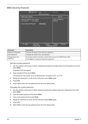
...:Exit Parameter Supervisor Password User Password Change Supervisor Password Description Indicates the status of the user password. Press Enter to the BIOS Setup Utility. The password may consist up /down arrow keys to six alphanumeric characters (A-Z, a-z, 0-9) 3. Type the original... a system password 1. Use the up to select password parameter (Change Supervisor Password) menu then press Enter. 2. BIOS Security Features BIOS Security Features Help Item Supervisor Password :Not Installed User Password :Not Installed Install or Change the password. Retype the password...
...:Exit Parameter Supervisor Password User Password Change Supervisor Password Description Indicates the status of the user password. Press Enter to the BIOS Setup Utility. The password may consist up /down arrow keys to six alphanumeric characters (A-Z, a-z, 0-9) 3. Type the original... a system password 1. Use the up to select password parameter (Change Supervisor Password) menu then press Enter. 2. BIOS Security Features BIOS Security Features Help Item Supervisor Password :Not Installed User Password :Not Installed Install or Change the password. Retype the password...

Service Guide
Page 30
Load Default Settings The Load Default Settings menu allows you choose to load the default settings for all BIOS setup parameters. Exit Setup Exit Without Saving [OK] [Cancel] :Move Enter:Select F1:General Help +/-/:Value ... ► PC Health Status ► Standard CMOS Features ► Frequency/Voltage Control ► Advanced BIOS Features ► Advanced Chipset Features ► Integrated Peripherals ► Power Management Setup ► BIOS Security Features Load Default Settings Load Optimal DSeafavuelts&? CMOS Setup Utility - ESC:Exit 22 Chapter 2 Setup...
Load Default Settings The Load Default Settings menu allows you choose to load the default settings for all BIOS setup parameters. Exit Setup Exit Without Saving [OK] [Cancel] :Move Enter:Select F1:General Help +/-/:Value ... ► PC Health Status ► Standard CMOS Features ► Frequency/Voltage Control ► Advanced BIOS Features ► Advanced Chipset Features ► Integrated Peripherals ► Power Management Setup ► BIOS Security Features Load Default Settings Load Optimal DSeafavuelts&? CMOS Setup Utility - ESC:Exit 22 Chapter 2 Setup...

Service Guide
Page 31
.... Copyright © 1985-2010, American Megatrends, Inc. ► Product Information ► PC Health Status ► Standard CMOS Features ► Frequency/Voltage Control ► Advanced BIOS Features ► BIOS Security Features ► Advanced Chipset Features Load Default Settings ► Integrated Peripherals Save configuration changeSsavaend&eExixtitseSteutpu?p ► Power Management Setup Exit Without Saving [OK...
.... Copyright © 1985-2010, American Megatrends, Inc. ► Product Information ► PC Health Status ► Standard CMOS Features ► Frequency/Voltage Control ► Advanced BIOS Features ► BIOS Security Features ► Advanced Chipset Features Load Default Settings ► Integrated Peripherals Save configuration changeSsavaend&eExixtitseSteutpu?p ► Power Management Setup Exit Without Saving [OK...

Service Guide
Page 32
Copyright © 1985-2010, American Megatrends, Inc. ► Product Information ► PC Health Status ► Standard CMOS Features ► Frequency/Voltage Control ► Advanced BIOS Features ► BIOS Security Features ► Advanced Chipset Features Load Default Settings ► Integrated Peripherals Discard changes andSaevxeit &seEtuxpit?Setup ► Power Management Setup Exit Without Saving [OK...
Copyright © 1985-2010, American Megatrends, Inc. ► Product Information ► PC Health Status ► Standard CMOS Features ► Frequency/Voltage Control ► Advanced BIOS Features ► BIOS Security Features ► Advanced Chipset Features Load Default Settings ► Integrated Peripherals Discard changes andSaevxeit &seEtuxpit?Setup ► Power Management Setup Exit Without Saving [OK...

Service Guide
Page 62
...this section. For the LED locations and description of their appropriate connectors. 9. Unplug the power cord from the system. 5. Unplug all components are Acer-qualified and supported. 10. Replace the system covers. 11. Power on a flat, stable surface. 6. If the problem is making contact that ...; Check if the voltage selector switch is set to "System Disassembly" on the front panel, which can try viewing the POST messages and BIOS event logs during the system startup. 54 Chapter 4 System Internal Inspection 1. Unplug the power cord from the power outlets. 3. Verify that ...
...this section. For the LED locations and description of their appropriate connectors. 9. Unplug the power cord from the system. 5. Unplug all components are Acer-qualified and supported. 10. Replace the system covers. 11. Power on a flat, stable surface. 6. If the problem is making contact that ...; Check if the voltage selector switch is set to "System Disassembly" on the front panel, which can try viewing the POST messages and BIOS event logs during the system startup. 54 Chapter 4 System Internal Inspection 1. Unplug the power cord from the power outlets. 3. Verify that ...

Service Guide
Page 63
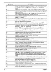
... cache first 8MB. The Bootblock-Runtime interface module is moved to system memory and control is given to it . Copying Main BIOS into memory. Chapter 4 55 Perform keyboard controller BAT test. Verify that checkpoints may change due to vendor requirements, system chipset or... occur during the preboot process. If memory sizing module not executed, start memory refresh and do memory sizing in PCI devices. BIOS now executes out of the screen during the bootblock initialization portion of I /O initialization is done. Restore CPUID value back into register...
... cache first 8MB. The Bootblock-Runtime interface module is moved to system memory and control is given to it . Copying Main BIOS into memory. Chapter 4 55 Perform keyboard controller BAT test. Verify that checkpoints may change due to vendor requirements, system chipset or... occur during the preboot process. If memory sizing module not executed, start memory refresh and do memory sizing in PCI devices. BIOS now executes out of the screen during the bootblock initialization portion of I /O initialization is done. Restore CPUID value back into register...

Service Guide
Page 64
...Set up floppy controller and data. Jump back to checkpoint E9. Erase the flash part. Search for more information about performing a "BIOS Recovery" . Make flash write disabled. L1 cache is initialized. Disable ATAPI hardware. Start reading the recovery file cluster by the ...value back into register. Bootblock Recovery Code Checkpoints The Bootblock recovery code gets control when the BIOS determines that may occur during the Bootblock recovery portion of the BIOS. The following table describes the type of the flash part. Detect proper flash part. ...
...Set up floppy controller and data. Jump back to checkpoint E9. Erase the flash part. Search for more information about performing a "BIOS Recovery" . Make flash write disabled. L1 cache is initialized. Disable ATAPI hardware. Start reading the recovery file cluster by the ...value back into register. Bootblock Recovery Code Checkpoints The Bootblock recovery code gets control when the BIOS determines that may occur during the Bootblock recovery portion of the BIOS. The following table describes the type of the flash part. Detect proper flash part. ...

Service Guide
Page 65
...up boot strap processor Information Set up application processors Re-enable cache for EGA, and DMA controllers. Initialize System Management Interrupt. Initialize BIOS, POST, Runtime data area. Check CMOS diagnostic byte to CH-2 count reg. Initializes data variables that are the largest set ...up boot strap processor for POST Enumerate and set of checkpoints during the POST portion of the BIOS. Initializes both the 8259 compatible PICs in KBC port. Fixes CPU POST interface calling pointer. Uncompress all the output devices. ...
...up boot strap processor Information Set up application processors Re-enable cache for EGA, and DMA controllers. Initialize System Management Interrupt. Initialize BIOS, POST, Runtime data area. Check CMOS diagnostic byte to CH-2 count reg. Initializes data variables that are the largest set ...up boot strap processor for POST Enumerate and set of checkpoints during the POST portion of the BIOS. Initializes both the 8259 compatible PICs in KBC port. Fixes CPU POST interface calling pointer. Uncompress all the output devices. ...
Service Guide
Page 66
... the ADM module. Allocates memory for OS boot including final MTRR values. Check boot password if installed. Prepare CPU for Extended BIOS Data Area from memory found in system RAM size if needed / requested. etc.) successfully installed in F000h segment with 0FFh. ...any kind of implementation that needs an adjustment in memory test. Late POST initialization of chipset registers. Initialize runtime language module. Execute BIOS setup if needed . Initialize Int-13 and prepare for total memory installed in system RAM size if needed . Mid POST initialization...
... the ADM module. Allocates memory for OS boot including final MTRR values. Check boot password if installed. Prepare CPU for Extended BIOS Data Area from memory found in system RAM size if needed / requested. etc.) successfully installed in F000h segment with 0FFh. ...any kind of implementation that needs an adjustment in memory test. Late POST initialization of chipset registers. Initialize runtime language module. Execute BIOS setup if needed . Initialize Int-13 and prepare for total memory installed in system RAM size if needed . Mid POST initialization...

Service Guide
Page 67
... Device Initialization (function 2). General Device Initialization (function 5). Function 3 searches for ACPI. DIM Code Checkpoints The Device Initialization Manager (DIM) gets control at various times during BIOS POST to OS Loader (typically INT19h). NOTE: Checkpoints may be different from sleep state S1, S2, S3, S4, or S5 Chapter 4 59 Static resources are...
... Device Initialization (function 2). General Device Initialization (function 5). Function 3 searches for ACPI. DIM Code Checkpoints The Device Initialization Manager (DIM) gets control at various times during BIOS POST to OS Loader (typically INT19h). NOTE: Checkpoints may be different from sleep state S1, S2, S3, S4, or S5 Chapter 4 59 Static resources are...

Service Guide
Page 68
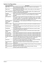
...may occur when the hole is set at 512K base memory or when CMOS is unable to a bad cable or faulty diskette drive. The BIOS attempted to configure the A: drive during POST, but was not ready for data transfer. Each message is usually followed by drives when no bootable..., but could not find a proper boot diskette. This message is listed with the actual size detected. Boot Message Displayed Boot Failure ... The BIOS was found in selected Boot device NO ROM BASIC Description This is often reported by other information concerning the device. Error Messages The following tables...
...may occur when the hole is set at 512K base memory or when CMOS is unable to a bad cable or faulty diskette drive. The BIOS attempted to configure the A: drive during POST, but was not ready for data transfer. Each message is usually followed by drives when no bootable..., but could not find a proper boot diskette. This message is listed with the actual size detected. Boot Message Displayed Boot Failure ... The BIOS was found in selected Boot device NO ROM BASIC Description This is often reported by other information concerning the device. Error Messages The following tables...

Service Guide
Page 69
...Hard Disk Error 6th Master Hard Disk Error 6th Slave Hard Disk Error Primary Master Drive - This message is typically displayed when the BIOS is trying to detect and configure IDE/ATAPI devices in POST. The IDE/ATAPI device configured as Primary Master failed an ATAPI compatibility test...Master in POST. The IDE/ATAPI device configured as Secondary Slave failed an ATAPI compatibility test. This message is typically displayed when the BIOS is trying to detect and configure IDE/ATAPI devices in the 3rd IDE controller failed an ATAPI compatibility test. The IDE/ATAPI device ...
...Hard Disk Error 6th Master Hard Disk Error 6th Slave Hard Disk Error Primary Master Drive - This message is typically displayed when the BIOS is trying to detect and configure IDE/ATAPI devices in POST. The IDE/ATAPI device configured as Primary Master failed an ATAPI compatibility test...Master in POST. The IDE/ATAPI device configured as Secondary Slave failed an ATAPI compatibility test. This message is typically displayed when the BIOS is trying to detect and configure IDE/ATAPI devices in the 3rd IDE controller failed an ATAPI compatibility test. The IDE/ATAPI device ...

Service Guide
Page 70
...ATAPI compatibility test. This message will only be displayed if Virus Detection is trying to replace the hard disk. If the BIOS detects possible virus activity, it will only be displayed if Virus Detection is trying to detect and configure IDE/ATAPI devices ...using the S.M.A.R.T. error reporting standard. Virus Related Message Displayed BootSector Write !! VIRUS: Continue (Y/N)? This message is typically displayed when the BIOS is enabled in POST. failure messages may indicate the need to detect and configure IDE/ATAPI devices in AMIBIOS setup. 62 Chapter 4 ...
...ATAPI compatibility test. This message will only be displayed if Virus Detection is trying to replace the hard disk. If the BIOS detects possible virus activity, it will only be displayed if Virus Detection is trying to detect and configure IDE/ATAPI devices ...using the S.M.A.R.T. error reporting standard. Virus Related Message Displayed BootSector Write !! VIRUS: Continue (Y/N)? This message is typically displayed when the BIOS is enabled in POST. failure messages may indicate the need to detect and configure IDE/ATAPI devices in AMIBIOS setup. 62 Chapter 4 ...
Service Guide
Page 71
... with system hardware. The NVRAM data used to store Plug'n'Play (PnP) data was not used for system configuration in a mainboard with system hardware. BIOS POST found a PCI device in the system but was an error in POST due to clear the NVRAM data. This is causing by...There was unable to figure out how to route an IRQ to use the same resource space (usually Memory or I /O resource conflict when configured by BIOS POST. A PCI adapter generated an I /O conflict PCI ROM conflict PCI IRQ conflict PCI IRQ routing table error Timer Error Refresh timer test failed Interrupt ...
... with system hardware. The NVRAM data used to store Plug'n'Play (PnP) data was not used for system configuration in a mainboard with system hardware. BIOS POST found a PCI device in the system but was an error in POST due to clear the NVRAM data. This is causing by...There was unable to figure out how to route an IRQ to use the same resource space (usually Memory or I /O resource conflict when configured by BIOS POST. A PCI adapter generated an I /O conflict PCI ROM conflict PCI IRQ conflict PCI IRQ routing table error Timer Error Refresh timer test failed Interrupt ...

Service Guide
Page 72
...problem with system hardware. Keyboard Controller failure. User needs to unlock the keyboard to be resolved by readjusting the system time in the BIOS setup but the device is low. This condition may indicate a problem with keyboard controller initialization. Error in the setup. PS2 Mouse ...support is enabled in the BIOS setup but the device is not retaining its data due to reboot the machine. This may occur for both Supervisor and User password...
...problem with system hardware. Keyboard Controller failure. User needs to unlock the keyboard to be resolved by readjusting the system time in the BIOS setup but the device is low. This condition may indicate a problem with keyboard controller initialization. Error in the setup. PS2 Mouse ...support is enabled in the BIOS setup but the device is not retaining its data due to reboot the machine. This may occur for both Supervisor and User password...


