
Owners Manual
Page 2
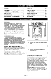
TABLE OF CONTENTS SAFETY 4 ASSEMBLY 8 CONTROLS and FEATURES 15 OPERATION 17 MAINTENANCE 24 SERVICE AND ADJUSTMENTS . ...located on the product registration form in operation position and facing the direction of forward travel. Refer to www.ariens.com. Registering the product will be dangerous and cause personal injury or property damage. All claims meeting requirements... do not register your product, please fill out, sign, and return the product registration card to Ariens or go to this manual for a replacement manual. MODEL AND SERIAL NUMBERS When ordering replacement parts ...
TABLE OF CONTENTS SAFETY 4 ASSEMBLY 8 CONTROLS and FEATURES 15 OPERATION 17 MAINTENANCE 24 SERVICE AND ADJUSTMENTS . ...located on the product registration form in operation position and facing the direction of forward travel. Refer to www.ariens.com. Registering the product will be dangerous and cause personal injury or property damage. All claims meeting requirements... do not register your product, please fill out, sign, and return the product registration card to Ariens or go to this manual for a replacement manual. MODEL AND SERIAL NUMBERS When ordering replacement parts ...

Owners Manual
Page 3
... function as described in this manual. 4. NOTICE: To locate your unit. Review Limited Warranty Policy. 6. Ariens disclaims liability for assistance. WARNING: Improper assembly or adjustments can cause serious injury. 2. Review recommended lubrication, maintenance and adjustments. 5. The replacement of this... 3. Some illustrations may be applicable to your nearest Ariens Dealer, go to www.ariens.com on the Internet. Do not operate the Sno-Thro unless all assembly instructions in this manual. DISCLAIMER Ariens reserves the right to discontinue, make changes to :...
... function as described in this manual. 4. NOTICE: To locate your unit. Review Limited Warranty Policy. 6. Ariens disclaims liability for assistance. WARNING: Improper assembly or adjustments can cause serious injury. 2. Review recommended lubrication, maintenance and adjustments. 5. The replacement of this... 3. Some illustrations may be applicable to your nearest Ariens Dealer, go to www.ariens.com on the Internet. Do not operate the Sno-Thro unless all assembly instructions in this manual. DISCLAIMER Ariens reserves the right to discontinue, make changes to :...
Owners Manual
Page 6
... starting engine, disengage control(s). ALWAYS allow moving part while unit is running. DO NOT overload the machine capacity by an Ariens Company dealer or an authorized engine manufacturer's service center. EMISSION CONTROL SYSTEM This equipment and/or its engine may operate unit... and cause an accident. can cause injury. Protect eyes, face and head from objects that may result in Owner/Operator Manual before assembly, maintenance or service. ALWAYS disengage attachment, stop before clearing snow. ALWAYS back up can cut. EN - 6 Tampering with side ...
... starting engine, disengage control(s). ALWAYS allow moving part while unit is running. DO NOT overload the machine capacity by an Ariens Company dealer or an authorized engine manufacturer's service center. EMISSION CONTROL SYSTEM This equipment and/or its engine may operate unit... and cause an accident. can cause injury. Protect eyes, face and head from objects that may result in Owner/Operator Manual before assembly, maintenance or service. ALWAYS disengage attachment, stop before clearing snow. ALWAYS back up can cut. EN - 6 Tampering with side ...

Owners Manual
Page 8
...4 Handlebar Spacer 6. 06435700 4 Flat Steel Washer 7. 06307400 4 Locking Washer 8. 06530200 4 5/16" Nyloc Nut 12 1 9. Use only Ariens approved parts; N/A 12. unapproved parts may void the unit warranty. 11 15 14 2 10 9 13 3 The following parts are missing contact... Sno-thro Unit: 1. N/A 13. 06900510 14. 06100007 15. 06305200 16. 02483859 17. 06212000 1 Upper Handlebar Assembly 1 Discharge Chute Assembly 1 Chute Crank Assembly 1 Literature Pack 1 Trigger Cable Assembly (921023) 1 1/4" x 1-1/2 Oval Head Machine Screw (921023) 1 1/4" Locking Washer (921023) 2 Skid Shoe,...
...4 Handlebar Spacer 6. 06435700 4 Flat Steel Washer 7. 06307400 4 Locking Washer 8. 06530200 4 5/16" Nyloc Nut 12 1 9. Use only Ariens approved parts; N/A 12. unapproved parts may void the unit warranty. 11 15 14 2 10 9 13 3 The following parts are missing contact... Sno-thro Unit: 1. N/A 13. 06900510 14. 06100007 15. 06305200 16. 02483859 17. 06212000 1 Upper Handlebar Assembly 1 Discharge Chute Assembly 1 Chute Crank Assembly 1 Literature Pack 1 Trigger Cable Assembly (921023) 1 1/4" x 1-1/2 Oval Head Machine Screw (921023) 1 1/4" Locking Washer (921023) 2 Skid Shoe,...

Owners Manual
Page 9
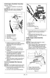
... 6. Mounting Hole Figure 4 2. Tighten all four bolts to block wheels or secure unit so it does not move during assembly. 1. One set to attach Figure 6 each side of attachment control cable to unit using two sets of frame. . 4 3 2. EN ... 1. Lower Handlebar 3. 5/16" x 2-1/4" Round Head Square Neck Grade 5 Bolt 4. Secure lower handlebar to the clutch arm. 3. Attachment Control Cable 4. Clutch Arm 2. ASSEMBLY Tools Required: • Pliers • Open-End Wrenches: 3/8, 7/16, 1/2, 9/16" and/or Adjustable Wrench • Tire Gauge • Torque Wrench (Optional) &#...
... 6. Mounting Hole Figure 4 2. Tighten all four bolts to block wheels or secure unit so it does not move during assembly. 1. One set to attach Figure 6 each side of attachment control cable to unit using two sets of frame. . 4 3 2. EN ... 1. Lower Handlebar 3. 5/16" x 2-1/4" Round Head Square Neck Grade 5 Bolt 4. Secure lower handlebar to the clutch arm. 3. Attachment Control Cable 4. Clutch Arm 2. ASSEMBLY Tools Required: • Pliers • Open-End Wrenches: 3/8, 7/16, 1/2, 9/16" and/or Adjustable Wrench • Tire Gauge • Torque Wrench (Optional) &#...
Owners Manual
Page 10
...all hardware. 4. Press cable anchor into mounting hole in Traction Drive Clutch Adjustment on page 29. 7. Attach remote trigger cable assembly to upper handlebar assembly using the cable ties attached to speed selector arm and adjust as specified in Attachment Clutch/Brake Adjustment on page 29. 8. ...Oval Head Machine Screw 3. Route the wire harness along the interior of the right side handlebar. 2. Trigger Cable Assembly 2. NOTICE: Be careful not to the engine electrical plug. 3. Shift Rod Hardware 3. Shift Rod 4. Remove packaging around shift rod. 5. ...
...all hardware. 4. Press cable anchor into mounting hole in Traction Drive Clutch Adjustment on page 29. 7. Attach remote trigger cable assembly to upper handlebar assembly using the cable ties attached to speed selector arm and adjust as specified in Attachment Clutch/Brake Adjustment on page 29. 8. ...Oval Head Machine Screw 3. Route the wire harness along the interior of the right side handlebar. 2. Trigger Cable Assembly 2. NOTICE: Be careful not to the engine electrical plug. 3. Shift Rod Hardware 3. Shift Rod 4. Remove packaging around shift rod. 5. ...

Owners Manual
Page 12
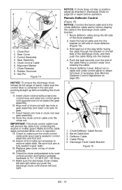
... 4. Remove the gear cover from below and install assembly into nylon bushing in control panel from top of the control panel, insert control assembly into control panel. 1 1. NOTICE: Make sure alignment markers on the gear assembly with your finger and rotate the discharge chute so ...Make sure the chute control cable is pointing straight ahead. 6. Control Assembly 2. Nylon Bushing 3. Remove rubber grommet from control panel. 7. Socket, 3/4" Figure 13 EN - 12 Release the lock arm on gear assembly are lined up when discharge chute is routed between the lower handlebar ...
... 4. Remove the gear cover from below and install assembly into nylon bushing in control panel from top of the control panel, insert control assembly into control panel. 1 1. NOTICE: Make sure alignment markers on the gear assembly with your finger and rotate the discharge chute so ...Make sure the chute control cable is pointing straight ahead. 6. Control Assembly 2. Nylon Bushing 3. Remove rubber grommet from control panel. 7. Socket, 3/4" Figure 13 EN - 12 Release the lock arm on gear assembly are lined up when discharge chute is routed between the lower handlebar ...
Owners Manual
Page 13
... bracket. 1. Check deflector travel , if necessary (see Remote Deflector Control Adjustment on page 28 or repair before clipping the cable to remove cable slack. Deflector Cable 4. Chute Rod 2. Gear Assembly 5. Chute Deflector Cable Anchor 2. Insert chute rod end without ears into control lever and .... Push the seal securely over the end of travel, make sure the chute control cable ends are properly seated in chute rod near gear assembly. 12. Barrel Cable End 3. Chute Control Cable 6. Hair Pin Figure 14 9 1 7 NOTICE: To ensure the discharge chute follows its...
... bracket. 1. Check deflector travel , if necessary (see Remote Deflector Control Adjustment on page 28 or repair before clipping the cable to remove cable slack. Deflector Cable 4. Chute Rod 2. Gear Assembly 5. Chute Deflector Cable Anchor 2. Insert chute rod end without ears into control lever and .... Push the seal securely over the end of travel, make sure the chute control cable ends are properly seated in chute rod near gear assembly. 12. Barrel Cable End 3. Chute Control Cable 6. Hair Pin Figure 14 9 1 7 NOTICE: To ensure the discharge chute follows its...
Owners Manual
Page 14
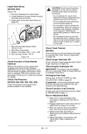
...perform the job. • Do not inflate the tires above the recommended pressure. • Do not weld or heat a wheel and tire assembly. Nut, Locking, Center, .38-16 Figure 16 Check Function of tire and rim parts is released, then both clutch levers. Attachment clutch ... Controls Ensure unit runs and performs properly. Check Engine Crankcase Oil IMPORTANT: The engine may be shipped with oil in front or over the tire assembly when inflating. Adjust clutch idler according to OPERATION on page 27). 1 2 3 4 1. Adjust skid shoes (see Skid Shoes on page 17. Skid...
...perform the job. • Do not inflate the tires above the recommended pressure. • Do not weld or heat a wheel and tire assembly. Nut, Locking, Center, .38-16 Figure 16 Check Function of tire and rim parts is released, then both clutch levers. Attachment clutch ... Controls Ensure unit runs and performs properly. Check Engine Crankcase Oil IMPORTANT: The engine may be shipped with oil in front or over the tire assembly when inflating. Adjust clutch idler according to OPERATION on page 27). 1 2 3 4 1. Adjust skid shoes (see Skid Shoes on page 17. Skid...
Owners Manual
Page 33
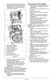
...friction disc. Install left bearing flange from hex shaft. 7. Traction Belt Idler 4. Swing Gate Pivot Bushing Figure 40 5. NOTICE: Make sure the drive plate assembly return spring remains connected to 5 - 6 lbf-ft (6.78 - 8.14 N•m). 13. Remove left bearing using recoil starter handle). 7 8 2... 3 5 1 6 9 4 1. Put the new friction disc in the frame. 8. Slide hex shaft through new friction disc assembly. Connect pivot pin to turn engine pulley using hardware removed in frame. Replace bottom cover. 19. Adjust traction drive clutch (see Speed Selector ...
...friction disc. Install left bearing flange from hex shaft. 7. Traction Belt Idler 4. Swing Gate Pivot Bushing Figure 40 5. NOTICE: Make sure the drive plate assembly return spring remains connected to 5 - 6 lbf-ft (6.78 - 8.14 N•m). 13. Remove left bearing using recoil starter handle). 7 8 2... 3 5 1 6 9 4 1. Put the new friction disc in the frame. 8. Slide hex shaft through new friction disc assembly. Connect pivot pin to turn engine pulley using hardware removed in frame. Replace bottom cover. 19. Adjust traction drive clutch (see Speed Selector ...

Owners Manual
Page 34
Bearing Flange 3. Drive Plate Assembly 7. Make sure that height adjuster lock finger is pulling to reduce track 7 tension. 2. Loosen jam nuts on the track midway between the upper and rear ...
Bearing Flange 3. Drive Plate Assembly 7. Make sure that height adjuster lock finger is pulling to reduce track 7 tension. 2. Loosen jam nuts on the track midway between the upper and rear ...
Owners Manual
Page 41
... accessory, or attachment which vary from Ariens Company. • Operating the utility vehicle when it has not been completely and properly assembled and pre-delivered by the Australian Consumer Law. EN - 41 Sno-Chore 2013 Ariens Company does not warrant this warranty shall...mower blades, mower vanes, brushes, headlights, light bulbs, knives, cutters, and single-stage impellers. • Any misuse, alteration, improper assembly, improper adjustment, neglect, or accident which the unit was originally distributed. If the law of your country. Different areas may also have significantly...
... accessory, or attachment which vary from Ariens Company. • Operating the utility vehicle when it has not been completely and properly assembled and pre-delivered by the Australian Consumer Law. EN - 41 Sno-Chore 2013 Ariens Company does not warrant this warranty shall...mower blades, mower vanes, brushes, headlights, light bulbs, knives, cutters, and single-stage impellers. • Any misuse, alteration, improper assembly, improper adjustment, neglect, or accident which the unit was originally distributed. If the law of your country. Different areas may also have significantly...
