

Owners Manual
Page 1
.... 921 Series Sno-Thro ® Owner/Operator Manual Manuel Du Propriétaire/Utilisateur Models 921023 - Deluxe 28 Track (SN 095000 +) 921024 - ENGLISH FRANÇAIS 04585100B 7/13 Printed in USA Deluxe 24 Platinum (SN 000101 +) 921029 - Deluxe 30 (SN 000101 +) 921035 - L'utilisation d'une essence contenant plus de 10% d'éthanol (E10) ou de...
.... 921 Series Sno-Thro ® Owner/Operator Manual Manuel Du Propriétaire/Utilisateur Models 921023 - Deluxe 28 Track (SN 095000 +) 921024 - ENGLISH FRANÇAIS 04585100B 7/13 Printed in USA Deluxe 24 Platinum (SN 000101 +) 921029 - Deluxe 30 (SN 000101 +) 921035 - L'utilisation d'une essence contenant plus de 10% d'éthanol (E10) ou de...
Owners Manual
Page 2
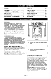
...MODEL AND SERIAL NUMBERS When ordering replacement parts or making service inquiries, know the Model and Serial numbers of purchase. PRODUCT REGISTRATION The Ariens dealer must register the product at the time of your unit and engine. Registering the product will help the company process warranty claims ... and maintenance. Customer Note: If the dealer does not register your product, please fill out, sign, and return the product registration card to Ariens or go to left, right, front, or rear are given from operator standing in operation position and facing the direction of purchase if you ...
...MODEL AND SERIAL NUMBERS When ordering replacement parts or making service inquiries, know the Model and Serial numbers of purchase. PRODUCT REGISTRATION The Ariens dealer must register the product at the time of your unit and engine. Registering the product will help the company process warranty claims ... and maintenance. Customer Note: If the dealer does not register your product, please fill out, sign, and return the product registration card to Ariens or go to left, right, front, or rear are given from operator standing in operation position and facing the direction of purchase if you ...

Owners Manual
Page 3
... in this unit and may not be optional. Fill out a Product Registration Card and return the card to the Ariens Company or go to www.ariens.com on the Internet. Equipment described within this manual. Make sure all Safety Precautions provided in this product without public...use of any part on the Internet. If you have difficulty following the instructions, contact your unit. UNAUTHORIZED REPLACEMENT PARTS Use only Ariens replacement parts. Some illustrations may void the warranty. Do not operate the Sno-Thro unless all assembly instructions in this manual may ...
... in this unit and may not be optional. Fill out a Product Registration Card and return the card to the Ariens Company or go to www.ariens.com on the Internet. Equipment described within this manual. Make sure all Safety Precautions provided in this product without public...use of any part on the Internet. If you have difficulty following the instructions, contact your unit. UNAUTHORIZED REPLACEMENT PARTS Use only Ariens replacement parts. Some illustrations may void the warranty. Do not operate the Sno-Thro unless all assembly instructions in this manual may ...

Owners Manual
Page 4
They mean: Attention! Obey The Message! NOTATIONS NOTICE: General reference information for Safety Decal locations. 1 2 WARNING: POTENTIALLY HAZARDOUS SITUATION! Learn applicable rules and laws in this manual. loaned, rented or sold, ALWAYS provide this unit was instructed by someone other than original purchaser; If not 3 avoided, MAY RESULT in death or serious injury. Understand and follow the practices set forth in your hand to Figure 2 below are used by the seller on safe and proper operation. Always follow all safety messages. SAFETY DECALS AND LOCATIONS ...
They mean: Attention! Obey The Message! NOTATIONS NOTICE: General reference information for Safety Decal locations. 1 2 WARNING: POTENTIALLY HAZARDOUS SITUATION! Learn applicable rules and laws in this manual. loaned, rented or sold, ALWAYS provide this unit was instructed by someone other than original purchaser; If not 3 avoided, MAY RESULT in death or serious injury. Understand and follow the practices set forth in your hand to Figure 2 below are used by the seller on safe and proper operation. Always follow all safety messages. SAFETY DECALS AND LOCATIONS ...

Owners Manual
Page 5
DANGER! Keep children out of work area and under watchful care of auger while engine is running. • Read Operator's Manual. • Allow operation only by properly trained adult, never children. • Stop engine and remove ignition key prior to leaving the operator's position for all moving parts to stop before making any reason. • Keep all controls, guards and safety devices properly serviced and functional. • Never direct discharge towards persons or property that may be injured or damaged by thrown objects. ROTATING PARTS! High speed impeller rotates below...
DANGER! Keep children out of work area and under watchful care of auger while engine is running. • Read Operator's Manual. • Allow operation only by properly trained adult, never children. • Stop engine and remove ignition key prior to leaving the operator's position for all moving parts to stop before making any reason. • Keep all controls, guards and safety devices properly serviced and functional. • Never direct discharge towards persons or property that may be injured or damaged by thrown objects. ROTATING PARTS! High speed impeller rotates below...
Owners Manual
Page 6
... stop before assembly, maintenance or service. Before starting units equipped with electric starter. DO NOT overload the machine capacity by an Ariens Company dealer or an authorized engine manufacturer's service center. ALWAYS back up can cause injury or death. EN - 6 SAFETY ...fog, etc. NEVER operate unit after or during operation. Rotating parts can cause injury and property damage. NEVER place your Ariens Company Equipment Retailer concerning emission controls and component questions. Never direct discharge towards persons or property that may result in an emergency...
... stop before assembly, maintenance or service. Before starting units equipped with electric starter. DO NOT overload the machine capacity by an Ariens Company dealer or an authorized engine manufacturer's service center. ALWAYS back up can cause injury or death. EN - 6 SAFETY ...fog, etc. NEVER operate unit after or during operation. Rotating parts can cause injury and property damage. NEVER place your Ariens Company Equipment Retailer concerning emission controls and component questions. Never direct discharge towards persons or property that may result in an emergency...
Owners Manual
Page 7
Immediately stop . ALWAYS shut off engine before restart. Never carry passengers. All motion of trouble. When parking on the ground away from your unit. Secure unit chassis to cool before filling. NEVER secure from spark plug. Keep unit free of slopes. This product is used, must stop . Always place containers on a slope always block the wheels. DO NOT change clothing immediately. DO NOT run engine in speed or direction. Damaged or worn out muffler can cause injury or death. NEVER store unit with fuel in any enclosure. See Engine Manual for your vehicle before...
Immediately stop . ALWAYS shut off engine before restart. Never carry passengers. All motion of trouble. When parking on the ground away from your unit. Secure unit chassis to cool before filling. NEVER secure from spark plug. Keep unit free of slopes. This product is used, must stop . Always place containers on a slope always block the wheels. DO NOT change clothing immediately. DO NOT run engine in speed or direction. Damaged or worn out muffler can cause injury or death. NEVER store unit with fuel in any enclosure. See Engine Manual for your vehicle before...

Owners Manual
Page 8
Qty Description The following parts are included as part of the Sno-thro Unit: 1. Use only Ariens approved parts; unapproved parts may void the unit warranty. 11 15 14 2 10 9 13 3 The following parts are missing contact your package ... x .083 (921029, 032) 19. 06529600 4 Nut, Locking, Center, .38-16 (921029, 032) If any of the contents listed are included as a part of your local Ariens dealer. PACKAGE CONTENTS Check the contents of the Lower Handlebar: 3. 00597451 1 Lower Handlebar 4. 06221600 4 5/16" x 2-1/4" Round Head Square Neck Grade 5 Bolt 5. 07500005 4 Handlebar ...
Qty Description The following parts are included as part of the Sno-thro Unit: 1. Use only Ariens approved parts; unapproved parts may void the unit warranty. 11 15 14 2 10 9 13 3 The following parts are missing contact your package ... x .083 (921029, 032) 19. 06529600 4 Nut, Locking, Center, .38-16 (921029, 032) If any of the contents listed are included as a part of your local Ariens dealer. PACKAGE CONTENTS Check the contents of the Lower Handlebar: 3. 00597451 1 Lower Handlebar 4. 06221600 4 5/16" x 2-1/4" Round Head Square Neck Grade 5 Bolt 5. 07500005 4 Handlebar ...

Owners Manual
Page 9
Handlebar Spacer 5. Wheel 3. Tighten all four bolts to hang from unit so lower handlebar mounting holes align with mounting holes on back of attachment control cable to the clutch arm. 3. Attachment Control Cable 4. Attach Upper Handlebar Assembly (Figures 5 and 6) 1. Lower Handlebar 3. 5/16" x 2-1/4" Round Head Square Neck Grade 5 Bolt 4. Lower Handlebar 2. NOTICE: DO NOT tighten hardware. Hook spring end of frame. . 4 3 2. EN - 9 Cable Eyelet 3. Allow upper handlebar assembly to 25 - 42 lbf-ft (33.9 - 56.9 N•m). Hook spring end of the ...
Handlebar Spacer 5. Wheel 3. Tighten all four bolts to hang from unit so lower handlebar mounting holes align with mounting holes on back of attachment control cable to the clutch arm. 3. Attachment Control Cable 4. Attach Upper Handlebar Assembly (Figures 5 and 6) 1. Lower Handlebar 3. 5/16" x 2-1/4" Round Head Square Neck Grade 5 Bolt 4. Lower Handlebar 2. NOTICE: DO NOT tighten hardware. Hook spring end of frame. . 4 3 2. EN - 9 Cable Eyelet 3. Allow upper handlebar assembly to 25 - 42 lbf-ft (33.9 - 56.9 N•m). Hook spring end of the ...
Owners Manual
Page 10
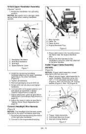
Shift Rod Hardware 3. Connect shift rod to the handlebars using one 1/4" x 1-1/2 oval head machine screw (Figure 3, Item 14) and one 1/4" locking washer (Figure 3, Item 15) (Figure 9). 2 3 1 1. Trigger Cable Assembly 2. Unfold Upper Handlebar Assembly (Figures 7 and 8) 1. Wire Harness 2 2. Cable Anchor 3 4. Tighten all hardware. 4. Connect Headlight Wire Harness (Figure 8) NOTICE: The headlight wire harness comes attached to damage cable spring hooks when rotating handlebar upward. . 4 1 1 2 3 4 1. Route the wire harness along the interior of the right side ...
Shift Rod Hardware 3. Connect shift rod to the handlebars using one 1/4" x 1-1/2 oval head machine screw (Figure 3, Item 14) and one 1/4" locking washer (Figure 3, Item 15) (Figure 9). 2 3 1 1. Trigger Cable Assembly 2. Unfold Upper Handlebar Assembly (Figures 7 and 8) 1. Wire Harness 2 2. Cable Anchor 3 4. Tighten all hardware. 4. Connect Headlight Wire Harness (Figure 8) NOTICE: The headlight wire harness comes attached to damage cable spring hooks when rotating handlebar upward. . 4 1 1 2 3 4 1. Route the wire harness along the interior of the right side ...

Owners Manual
Page 11
Mounting Holes 2. Mounting Hardware Figure 10 4. Insert the short end of the chute crank into the hole in the front of discharge chute ring (if not already greased). 2. Install Discharge Chute, Chute Control and Chute Rod (921028, 029) (Figures 12, 13 and 14) 1. Install discharge chute over opening in the auger housing. NOTICE: Leave discharge chute pedestal loose to help install the chute rod. Finger tighten the mounting hardware removed in step 2. NOTICE: Leave discharge chute pedestal loose to help install the chute crank. . 2 921023, 024, 030, 032, 035 3 1 1 2 3 5 4 1....
Mounting Holes 2. Mounting Hardware Figure 10 4. Insert the short end of the chute crank into the hole in the front of discharge chute ring (if not already greased). 2. Install Discharge Chute, Chute Control and Chute Rod (921028, 029) (Figures 12, 13 and 14) 1. Install discharge chute over opening in the auger housing. NOTICE: Leave discharge chute pedestal loose to help install the chute rod. Finger tighten the mounting hardware removed in step 2. NOTICE: Leave discharge chute pedestal loose to help install the chute crank. . 2 921023, 024, 030, 032, 035 3 1 1 2 3 5 4 1....

Owners Manual
Page 12
Mounting Hardware Figure 12 4. Control Assembly 2. Socket, 3/4" Figure 13 EN - 12 Remove rubber grommet from below and install assembly into nylon bushing in control panel from control panel. 7. Discharge Chute 3. NOTICE: Make sure alignment markers on the gear assembly with your finger and rotate the discharge chute so it points straight ahead. Make sure the chute control cable is pointing straight ahead. 6. Discharge Chute Ring 5. Push Nut 4. Nylon Bushing 3. Chute Pedestal 4. Release the lock arm on gear assembly are lined up when discharge chute is routed ...
Mounting Hardware Figure 12 4. Control Assembly 2. Socket, 3/4" Figure 13 EN - 12 Remove rubber grommet from below and install assembly into nylon bushing in control panel from control panel. 7. Discharge Chute 3. NOTICE: Make sure alignment markers on the gear assembly with your finger and rotate the discharge chute so it points straight ahead. Make sure the chute control cable is pointing straight ahead. 6. Discharge Chute Ring 5. Push Nut 4. Nylon Bushing 3. Chute Pedestal 4. Release the lock arm on gear assembly are lined up when discharge chute is routed ...
Owners Manual
Page 13
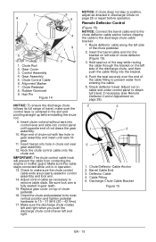
... the barrel cable end into the bracket. 4. Push the seal securely over the end of rod clears the gear assembly. 10. Adjust nut on page 28). . 2 3 1 3 5 4 1. Cable Fitting 5. Insert chute rod end without ears into control lever and slide into hole in gear teeth. 15. Hook the...cable hook will prevent the cable from entering the cable. 5. Hold seal out of the way while routing the cable through the bracket on page 28 or repair before clipping the cable to obtain full travel . Barrel Cable End 3. Control Assembly 4. Chute Deflector Cable Anchor 2. Deflector Cable 4. ...
... the barrel cable end into the bracket. 4. Push the seal securely over the end of rod clears the gear assembly. 10. Adjust nut on page 28). . 2 3 1 3 5 4 1. Cable Fitting 5. Insert chute rod end without ears into control lever and slide into hole in gear teeth. 15. Hook the...cable hook will prevent the cable from entering the cable. 5. Hold seal out of the way while routing the cable through the bracket on page 28 or repair before clipping the cable to obtain full travel . Barrel Cable End 3. Control Assembly 4. Chute Deflector Cable Anchor 2. Deflector Cable 4. ...
Owners Manual
Page 14
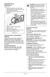
Skid Shoe, Reversible 3. Check Tire Pressure (921024, 028, 029, 030, 032, 035) Check tire pressure and adjust to OPERATION on tire sidewall. Heat can structurally weaken or deform the wheel. • Do not stand in Attachment Belt 1. remove the protective wrap from skid shoes. 2. Refer to the pressure listed on page 17. Run-in front or over the tire assembly when inflating. Adjust clutch idler according to stop, and remove spark plug wire. 4. Washer, Flat Steel .438 x 1.00 x .083 4. Welding can cause an increase in air pressure resulting in the attached bag. Fill...
Skid Shoe, Reversible 3. Check Tire Pressure (921024, 028, 029, 030, 032, 035) Check tire pressure and adjust to OPERATION on tire sidewall. Heat can structurally weaken or deform the wheel. • Do not stand in Attachment Belt 1. remove the protective wrap from skid shoes. 2. Refer to the pressure listed on page 17. Run-in front or over the tire assembly when inflating. Adjust clutch idler according to stop, and remove spark plug wire. 4. Washer, Flat Steel .438 x 1.00 x .083 4. Welding can cause an increase in air pressure resulting in the attached bag. Fill...

Owners Manual
Page 15
Headlight 6. Quick Turn Chute Control (921028, 029) EN - 15 Chute Crank 9. Belt Cover 5. Discharge Chute 7. Remote Discharge Chute Deflector 4. Clean-Out Tool 3. Skid Shoe 2. Impeller 8. CONTROLS AND FEATURES 921028, 029 9 8 3 6 2 5 8 4 3 6 2 5 7 4 1 7 1 Figure 17 1.
Headlight 6. Quick Turn Chute Control (921028, 029) EN - 15 Chute Crank 9. Belt Cover 5. Discharge Chute 7. Remote Discharge Chute Deflector 4. Clean-Out Tool 3. Skid Shoe 2. Impeller 8. CONTROLS AND FEATURES 921028, 029 9 8 3 6 2 5 8 4 3 6 2 5 7 4 1 7 1 Figure 17 1.

Owners Manual
Page 16
...) 8. Scraper Blade EN - 16 Electric Start 18. Recoil Starter Handle 12. Throttle 13. 3 7 6 18 19 Briggs & Stratton 14 9 10 20 12 11 5 15 13 11 4 2 1 8 Ariens AX 12,13 17 17 16 9 16 17 11 15 16 10 14 1. Auger 19. Fuel Tank and Cap 16. Oil Drain 9. Oil Fill/Dipstick...
...) 8. Scraper Blade EN - 16 Electric Start 18. Recoil Starter Handle 12. Throttle 13. 3 7 6 18 19 Briggs & Stratton 14 9 10 20 12 11 5 15 13 11 4 2 1 8 Ariens AX 12,13 17 17 16 9 16 17 11 15 16 10 14 1. Auger 19. Fuel Tank and Cap 16. Oil Drain 9. Oil Fill/Dipstick...
Owners Manual
Page 17
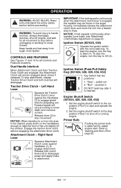
OPERATION WARNING: AVOID INJURY. CONTROLS AND FEATURES See Figures 17 and 18 for easier engine start. Immediately release the attachment clutch lever and move the unit into a heated area to Starting and Shut Off on snow thrower. To start and operate the engine. 2. "Run" - Set the engine shutoff switch to stop before proceeding. Primer Bulb Pushing the primer bulb in adds fuel for all movement to the stop movement. Refer to thaw. Keep hands and feet away from the area to be frozen in 1 DO NOT twist key after it is engaged, the impeller may be cleared, press down ...
OPERATION WARNING: AVOID INJURY. CONTROLS AND FEATURES See Figures 17 and 18 for easier engine start. Immediately release the attachment clutch lever and move the unit into a heated area to Starting and Shut Off on snow thrower. To start and operate the engine. 2. "Run" - Set the engine shutoff switch to stop before proceeding. Primer Bulb Pushing the primer bulb in adds fuel for all movement to the stop movement. Refer to thaw. Keep hands and feet away from the area to be frozen in 1 DO NOT twist key after it is engaged, the impeller may be cleared, press down ...
Owners Manual
Page 18
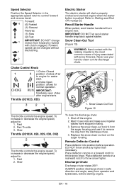
IMPORTANT: Gradually open choke after engine starts. Refer to control forward and reverse travel. Recoil Starter Handle When pulled, recoil starter handle will start . Snow Clean-Out Tool (Figure 19) WARNING: Hand contact with the rotating impeller is pushed. Slow Throttle (921024, 028, 029, 030, 032) 2 1 The throttle controls the engine speed. Slow To clear the discharge chute: 1. DO NOT throw snow any higher than necessary. Discharge Chute Discharge chute rotates 200°. Forward: 6 (6) Fastest (1) Slowest Reverse: (1) Slow (2) Fast 1 IMPORTANT: DO NOT change motion ...
IMPORTANT: Gradually open choke after engine starts. Refer to control forward and reverse travel. Recoil Starter Handle When pulled, recoil starter handle will start . Snow Clean-Out Tool (Figure 19) WARNING: Hand contact with the rotating impeller is pushed. Slow Throttle (921024, 028, 029, 030, 032) 2 1 The throttle controls the engine speed. Slow To clear the discharge chute: 1. DO NOT throw snow any higher than necessary. Discharge Chute Discharge chute rotates 200°. Forward: 6 (6) Fastest (1) Slowest Reverse: (1) Slow (2) Fast 1 IMPORTANT: DO NOT change motion ...

Owners Manual
Page 19
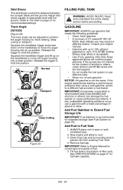
...-Turn Chute Control (921028, 029) (Figure 21) IMPORTANT: If chute does not stay in set position, adjust as directed in SERVICE AND ADJUSTMENTS on page 28, or repair before operation. EN - 19 unlock one wheel to wear too far or Auger/Impeller housing will not drive with the surface being cleared...
...-Turn Chute Control (921028, 029) (Figure 21) IMPORTANT: If chute does not stay in set position, adjust as directed in SERVICE AND ADJUSTMENTS on page 28, or repair before operation. EN - 19 unlock one wheel to wear too far or Auger/Impeller housing will not drive with the surface being cleared...
Owners Manual
Page 20
Refer to Pre-Start on the handlebars to move the auger housing into a down on the handlebars to move the auger housing into an up to 10% ethanol (gasohol) or up position. GASOLINE IMPORTANT: ALWAYS use a gasoline with a lower percentage of alcohol or ether. NOTICE: All gasoline is acceptable. • Use of any undesirable operating problems occur, use gasoline that meets the following guidelines: • Clean, fresh gasoline. • A minimum of alcohol or ethers, check ethanol and MTBE levels with alcohols or ethers) can be adjusted to cool. 3. Clean Fuel Cap and ...
Refer to Pre-Start on the handlebars to move the auger housing into a down on the handlebars to move the auger housing into an up to 10% ethanol (gasohol) or up position. GASOLINE IMPORTANT: ALWAYS use a gasoline with a lower percentage of alcohol or ether. NOTICE: All gasoline is acceptable. • Use of any undesirable operating problems occur, use gasoline that meets the following guidelines: • Clean, fresh gasoline. • A minimum of alcohol or ethers, check ethanol and MTBE levels with alcohols or ethers) can be adjusted to cool. 3. Clean Fuel Cap and ...
