
User Manual
Page 3
Contents Notices...vi Safety information vii About this guide viii M4A785-M specifications summary x Chapter 1: Product introduction 1.1 Welcome 1-1 1.2 Package contents 1-1 1.3 Special features 1-1 1.3.1 Product highlights 1-1 1.3.2 Innovative ASUS features 1-3 1.4 Before you proceed 1-5 1.5 Motherboard overview 1-6 1.5.1 Placement direction 1-6 1.5.2 Screw holes 1-6 1.5.3 Motherboard layout 1-7 1.5.4 Layout contents 1-7 1.6 Central Processing Unit ...x1 slot 1-18 1.8.5 PCI Express x16 slot 1-18 1.9 Jumpers 1-19 1.10 Connectors 1-20 1.10.1 Rear panel ports 1-20 1.10.2 Internal...
Contents Notices...vi Safety information vii About this guide viii M4A785-M specifications summary x Chapter 1: Product introduction 1.1 Welcome 1-1 1.2 Package contents 1-1 1.3 Special features 1-1 1.3.1 Product highlights 1-1 1.3.2 Innovative ASUS features 1-3 1.4 Before you proceed 1-5 1.5 Motherboard overview 1-6 1.5.1 Placement direction 1-6 1.5.2 Screw holes 1-6 1.5.3 Motherboard layout 1-7 1.5.4 Layout contents 1-7 1.6 Central Processing Unit ...x1 slot 1-18 1.8.5 PCI Express x16 slot 1-18 1.9 Jumpers 1-19 1.10 Connectors 1-20 1.10.1 Rear panel ports 1-20 1.10.2 Internal...

User Manual
Page 11
GPU NOS * GPU NOS is not supported in Hybrid CrossFireX™ mode. M4A785-M specifications summary Storage Audio USB LAN ASUS unique features ASUS overclocking features Back panel I/O ports 1 x Ultra DMA 133/100/66 connector for up to 12 USB 2.0/1.1 ports (6 ports at mid-board, 6 ports at 1MHz increment - SFS (Stepless Frequency Selection): - Turbo Key - PCIe frequency...
GPU NOS * GPU NOS is not supported in Hybrid CrossFireX™ mode. M4A785-M specifications summary Storage Audio USB LAN ASUS unique features ASUS overclocking features Back panel I/O ports 1 x Ultra DMA 133/100/66 connector for up to 12 USB 2.0/1.1 ports (6 ports at mid-board, 6 ports at 1MHz increment - SFS (Stepless Frequency Selection): - Turbo Key - PCIe frequency...
User Manual
Page 12
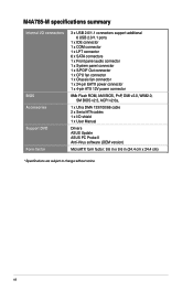
M4A785-M specifications summary Internal I/O connectors BIOS Accessories Support DVD Form factor 3 x USB 2.0/1.1 connectors support additional 6 USB 2.0/1.1 ports 1 x IDE connector 1 x COM connector 1 x LPT connector 6 x SATA connectors 1 x Front panel audio connector 1 x System panel connector 1 x S/PDIF Out connector 1 x CPU fan connector 1 x Chassis fan connector 1 x 24-pin EATX power connector 1 x 4-pin ATX 12V power connector 8Mb Flash ROM, AMI BIOS, PnP, DMI v2.0, WfM2.0, SM BIOS v2.5, ACPI v2.0a, 1 x Ultra DMA...
M4A785-M specifications summary Internal I/O connectors BIOS Accessories Support DVD Form factor 3 x USB 2.0/1.1 connectors support additional 6 USB 2.0/1.1 ports 1 x IDE connector 1 x COM connector 1 x LPT connector 6 x SATA connectors 1 x Front panel audio connector 1 x System panel connector 1 x S/PDIF Out connector 1 x CPU fan connector 1 x Chassis fan connector 1 x 24-pin EATX power connector 1 x 4-pin ATX 12V power connector 8Mb Flash ROM, AMI BIOS, PnP, DMI v2.0, WfM2.0, SM BIOS v2.5, ACPI v2.0a, 1 x Ultra DMA...

User Manual
Page 19
ATX power connectors (24-pin EATXPWR, 4-pin ATX12V) 3. LPT connector (26-1 pin LPT) 7. IDE connector (40-1 pin PRI_IDE) Page Connectors/Jumpers/Slots/LED 1-29 8. System panel connector (20-8 pin PANEL) 1-26 1-11 11. Onboard power LED (SB_PWR) 1-27 12. 1.5.3 Motherboard layout 1.5.4 Layout contents Connectors/Jumpers/Slots/LED 1. USB connectors (10-1 pin USB78, USB910, 1-27 USB1112) 1-29 13. DDR2 DIMM slots 5. Clear RTC...
ATX power connectors (24-pin EATXPWR, 4-pin ATX12V) 3. LPT connector (26-1 pin LPT) 7. IDE connector (40-1 pin PRI_IDE) Page Connectors/Jumpers/Slots/LED 1-29 8. System panel connector (20-8 pin PANEL) 1-26 1-11 11. Onboard power LED (SB_PWR) 1-27 12. 1.5.3 Motherboard layout 1.5.4 Layout contents Connectors/Jumpers/Slots/LED 1. USB connectors (10-1 pin USB78, USB910, 1-27 USB1112) 1-29 13. DDR2 DIMM slots 5. Clear RTC...
User Manual
Page 32
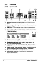
... port is for a PS/2 keyboard or mouse. 2. VGA port. In the 4, 6 and 8-channel configurations, the function of this port becomes Front Speaker Out. 9. 1.10 1.10.1 Connectors Rear panel ports 1. This port connects to the rear speakers in the 8-channel audio configuration. 1-20 Chapter 1: Product introduction
... port is for a PS/2 keyboard or mouse. 2. VGA port. In the 4, 6 and 8-channel configurations, the function of this port becomes Front Speaker Out. 9. 1.10 1.10.1 Connectors Rear panel ports 1. This port connects to the rear speakers in the 8-channel audio configuration. 1-20 Chapter 1: Product introduction

User Manual
Page 33
...Start > Control Panel > Sounds and Audio Devices > Sound Playback to configure the settings. 11. USB 2.0 ports 1 and 2. USB 2.0 ports 3 and 4. HDMI port. This port is for USB 2.0 devices. 12. The dual display function works only under Windows. DVI-D port. ASUS M4A785-M 1-21 Dual... display output support • This table indicates that whether the following dual display outputs are for a High-Definition Multimedia Interface (HDMI) connector, and is VIA High Definition Audio (the name may be different based on your motherboard: Dual display...
...Start > Control Panel > Sounds and Audio Devices > Sound Playback to configure the settings. 11. USB 2.0 ports 1 and 2. USB 2.0 ports 3 and 4. HDMI port. This port is for USB 2.0 devices. 12. The dual display function works only under Windows. DVI-D port. ASUS M4A785-M 1-21 Dual... display output support • This table indicates that whether the following dual display outputs are for a High-Definition Multimedia Interface (HDMI) connector, and is VIA High Definition Audio (the name may be different based on your motherboard: Dual display...

User Manual
Page 38
... is for the chassis-mounted reset button for the HDD Activity LED. System panel connector (20-8 pin PANEL) This connector supports several chassis-mounted functions. • System power LED (2-pin PLED) This 2-pin connector is for the system power button. Connect the chassis power LED cable to this...lights up when you to the HDD. • System warning speaker (4-pin SPEAKER) This 4-pin connector is read from or written to hear system beeps and warnings. • ATX power button/soft-off the system power. 1-26 Chapter 1: Product introduction The speaker allows you turn...
... is for the chassis-mounted reset button for the HDD Activity LED. System panel connector (20-8 pin PANEL) This connector supports several chassis-mounted functions. • System power LED (2-pin PLED) This 2-pin connector is for the system power button. Connect the chassis power LED cable to this...lights up when you to the HDD. • System warning speaker (4-pin SPEAKER) This 4-pin connector is read from or written to hear system beeps and warnings. • ATX power button/soft-off the system power. 1-26 Chapter 1: Product introduction The speaker allows you turn...

User Manual
Page 40
... section 2.4.4 Onboard Device Configuration for details. • The front panel audio I/O module is purchased separately. 8. Ensure that the audio device of the motherboard high-definition audio capability. • If you want to connect a high definition front panel audio module to this connector, set the Front Panel Select item in the BIOS to configure the setting...
... section 2.4.4 Onboard Device Configuration for details. • The front panel audio I/O module is purchased separately. 8. Ensure that the audio device of the motherboard high-definition audio capability. • If you want to connect a high definition front panel audio module to this connector, set the Front Panel Select item in the BIOS to configure the setting...


