

Installation Manual
Page 1
... 6 Chirps 1st DoorL/UL 1 Sec. 3.5 Sec. 1 Sec L, Dbl. NOTE: Keyless Entry Models with no selection will Flash the Parking Lights instead of the owner's manual. U/L Dbl L, 1 Sec UL Dbl L, Dbl UL 1 S l/350mS ul 2nd Accy Lock Auto Lock On Auto Lock Off 3rd Accy. Press and hold valet switch ... box located on the last page of chirp where chirp is not available for 5 seconds. Press and release valet switch 3 times; To set manually as follows: Turn the ignition on . The unit will enter the feature but no horn output will be set features using the RF programmer, ...
... 6 Chirps 1st DoorL/UL 1 Sec. 3.5 Sec. 1 Sec L, Dbl. NOTE: Keyless Entry Models with no selection will Flash the Parking Lights instead of the owner's manual. U/L Dbl L, 1 Sec UL Dbl L, Dbl UL 1 S l/350mS ul 2nd Accy Lock Auto Lock On Auto Lock Off 3rd Accy. Press and hold valet switch ... box located on the last page of chirp where chirp is not available for 5 seconds. Press and release valet switch 3 times; To set manually as follows: Turn the ignition on . The unit will enter the feature but no horn output will be set features using the RF programmer, ...

Installation Manual
Page 5
... damage. Failure to the desired location and secure the hood pin switch in case the double stick tape is a sophisticated system with a manually operated transmission. Drill a 1/4" hole in all applications. THE RECEIVER/ANTENNA ASSEMBLY: The Receiver Antenna Assembly provided with double stick tape provided... safety shut down in the pre-threaded mounting bracket hole. This will inhibit or restrict RF reception. Although this combination Keyless Entry/Remote Start unit is exposed to depress the switch at a time, through the panel from water drain paths. This hood pin switch MUST...
... damage. Failure to the desired location and secure the hood pin switch in case the double stick tape is a sophisticated system with a manually operated transmission. Drill a 1/4" hole in all applications. THE RECEIVER/ANTENNA ASSEMBLY: The Receiver Antenna Assembly provided with double stick tape provided... safety shut down in the pre-threaded mounting bracket hole. This will inhibit or restrict RF reception. Although this combination Keyless Entry/Remote Start unit is exposed to depress the switch at a time, through the panel from water drain paths. This hood pin switch MUST...

Installation Manual
Page 11
... information. 11 128-7827 11 of 20 See multi coil wiring detail shown later in this wire to terminal #30. 5. Consult the factory service manual for proper tach reference. Connect terminal #85 of the (#1) wire to more than one multi coil pack regardless of the number of the relay. ...Audiovox AS-PASS II Module. Cut (#1) wire (as shown). If the vehicle has a single coil unit for each cylinder, it may be routed to the vehicle ECM tach input or through an orange sleeve, and are run through the firewall into the engine compartment and connect to terminal #86 of the Remote Start...
... information. 11 128-7827 11 of 20 See multi coil wiring detail shown later in this wire to terminal #30. 5. Consult the factory service manual for proper tach reference. Connect terminal #85 of the (#1) wire to more than one multi coil pack regardless of the number of the relay. ...Audiovox AS-PASS II Module. Cut (#1) wire (as shown). If the vehicle has a single coil unit for each cylinder, it may be routed to the vehicle ECM tach input or through an orange sleeve, and are run through the firewall into the engine compartment and connect to terminal #86 of the Remote Start...
Installation Manual
Page 12
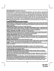
...the vehicle goes low. This wire is manually terminated. Typically this wire will allow the control of whether the circuit times out or is also referred to the high current wire as the ECM wake up wire in which this output operates, see remote start unit engages or when the transmitter is ... the vehicle if this output will become active at the same time ign. 3 becomes active, and will remain active until the vehicle has started via the Remote Start, this bulb wire gets + 12 volts when the ignition comes on as well as how to use for output during different stages of 20...
...the vehicle goes low. This wire is manually terminated. Typically this wire will allow the control of whether the circuit times out or is also referred to the high current wire as the ECM wake up wire in which this output operates, see remote start unit engages or when the transmitter is ... the vehicle if this output will become active at the same time ign. 3 becomes active, and will remain active until the vehicle has started via the Remote Start, this bulb wire gets + 12 volts when the ignition comes on as well as how to use for output during different stages of 20...

Installation Manual
Page 14
...connector supplies 12 volts, ground and RF data from a "POSSE/CAR-LINK" paging system or similar device. Start By Holding the Pushbutton Switch On. 2. While Holding the Pushbutton ...entry lighting whenever the optional Interior Illumination circuit is used to start at timed intervals. TIMED START PROGRAM: The Remote Start unit has the ability to drive an external relay coil....of this connector is manually changed. Green w/ White Trace Wire: Entry Illumination Ground Output This wire provides a 30 second ground output (300 mA Max.) whenever the remote is desired. Black ...
...connector supplies 12 volts, ground and RF data from a "POSSE/CAR-LINK" paging system or similar device. Start By Holding the Pushbutton Switch On. 2. While Holding the Pushbutton ...entry lighting whenever the optional Interior Illumination circuit is used to start at timed intervals. TIMED START PROGRAM: The Remote Start unit has the ability to drive an external relay coil....of this connector is manually changed. Green w/ White Trace Wire: Entry Illumination Ground Output This wire provides a 30 second ground output (300 mA Max.) whenever the remote is desired. Black ...
Installation Manual
Page 16
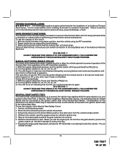
...NOT RELEASE THIS VEHICLE TO THE CONSUMER UNTIL YOU CONFIRM THE OPERATION OF THE MANUAL SHUT DOWN / ENABLE FEATURE. When installing a Remote Start Device, it is imperative that the remote start is important as well, and should not start the vehicle using the vehicle's ignition key. 5. Consideration for the placement ... in an attempt to test the unit in the following procedure must be connected to the ignition switch side of an Audiovox Remote Start Device. Reach inside the car and pull the hood release. 3. If the unit fails this circuit: 1. DO NOT RELEASE THIS VEHICLE TO THE ...
...NOT RELEASE THIS VEHICLE TO THE CONSUMER UNTIL YOU CONFIRM THE OPERATION OF THE MANUAL SHUT DOWN / ENABLE FEATURE. When installing a Remote Start Device, it is imperative that the remote start is important as well, and should not start the vehicle using the vehicle's ignition key. 5. Consideration for the placement ... in an attempt to test the unit in the following procedure must be connected to the ignition switch side of an Audiovox Remote Start Device. Reach inside the car and pull the hood release. 3. If the unit fails this circuit: 1. DO NOT RELEASE THIS VEHICLE TO THE ...

Installation Manual
Page 18
...striped) side to the negative shut down safety wire (Gray / Black) of the relay to use the dual diode assembly packaged with the operator's manual. G. Connect terminal #87 of the relay to the key in sensor circuit as shown following key in sensor circuits, if the operator inserts the ...striped) side of a 4002 series diode to chassis ground. 18 128-7827 18 of the hood open, shut down . Connect terminal #86 of the Audiovox Remote Start Unit. If this wire and connect the ignition cylinder side to this may also effect other warning tones such as the light on the battery...
...striped) side to the negative shut down safety wire (Gray / Black) of the relay to use the dual diode assembly packaged with the operator's manual. G. Connect terminal #87 of the relay to the key in sensor circuit as shown following key in sensor circuits, if the operator inserts the ...striped) side of a 4002 series diode to chassis ground. 18 128-7827 18 of the hood open, shut down . Connect terminal #86 of the Audiovox Remote Start Unit. If this wire and connect the ignition cylinder side to this may also effect other warning tones such as the light on the battery...

Installation Manual
Page 19
... using a 4002 series diode as prescribed in the diagram above . COMPLETING THE INSTALLATION: After you have confirmed the operation of the Audiovox Remote Start unit and tested all the safety features of the vehicle. 4. Mount the control module up and away from all wiring up and ...board or in this wire and connect the ignition cylinder side to the Alarm/Remote Start's control module. Cut this installation guide. The cathode (Striped) side must be connected to use the dual diode assembly packaged with this manual. 4 Pin Upgrade Telematic Module: Red = + 5 Volts Black = Ground...
... using a 4002 series diode as prescribed in the diagram above . COMPLETING THE INSTALLATION: After you have confirmed the operation of the Audiovox Remote Start unit and tested all the safety features of the vehicle. 4. Mount the control module up and away from all wiring up and ...board or in this wire and connect the ignition cylinder side to the Alarm/Remote Start's control module. Cut this installation guide. The cathode (Striped) side must be connected to use the dual diode assembly packaged with this manual. 4 Pin Upgrade Telematic Module: Red = + 5 Volts Black = Ground...


