

Installation Manual
Page 3
...Note: When averaging, the engine must be started 4 times with the key to RF feature program mode. Press and hold valet switch for 5 seconds. turn ignition off , or press and release valet switch. RF Programmable Features Bank 3 Is Remote Start Selectable Features: Feature Selection 1 Chirp 2 ...Chirps 3 Chirps 4 Chirps 1st Defrost Output Pulsed 10 Mins 2nd RF Start Chirp Off On On & Car Finder 3rd Run Time 5 Mins 10 Mins 15 Mins 20 Mins 4th...
...Note: When averaging, the engine must be started 4 times with the key to RF feature program mode. Press and hold valet switch for 5 seconds. turn ignition off , or press and release valet switch. RF Programmable Features Bank 3 Is Remote Start Selectable Features: Feature Selection 1 Chirp 2 ...Chirps 3 Chirps 4 Chirps 1st Defrost Output Pulsed 10 Mins 2nd RF Start Chirp Off On On & Car Finder 3rd Run Time 5 Mins 10 Mins 15 Mins 20 Mins 4th...
Installation Manual
Page 4
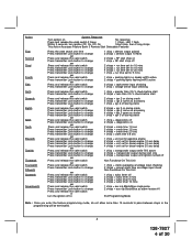
...sec delay 4 chirps = unit set for diesel engine 20 sec delay 1 chirp = transponder output while R/S active 2 chirps = transponder output during start only 3 chirps = transponder output until ignition turned off Non Functional On This Unit 1 chirp = crank averaging w/voltage input checking 2 chirps = ...flash Within 3 seconds, turn ignition Off, On, Off, On Short chirp, then 2 long chirps This Action Accesses Feature Bank 3 Remote Start Selectable Features Press the valet switch one time Press transmitter Lock button to change or Press and release the valet switch Press transmitter Lock button...
...sec delay 4 chirps = unit set for diesel engine 20 sec delay 1 chirp = transponder output while R/S active 2 chirps = transponder output during start only 3 chirps = transponder output until ignition turned off Non Functional On This Unit 1 chirp = crank averaging w/voltage input checking 2 chirps = ...flash Within 3 seconds, turn ignition Off, On, Off, On Short chirp, then 2 long chirps This Action Accesses Feature Bank 3 Remote Start Selectable Features Press the valet switch one time Press transmitter Lock button to change or Press and release the valet switch Press transmitter Lock button...

Installation Manual
Page 5
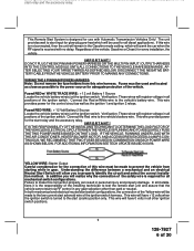
...and an Automatic Transmission. HOOD PIN SWITCH: The hood pin switch included in this will prevent the antenna from dropping down of the remote start is allowed for the body of 20 For direct mounting, a 1/4" hole must be used for valet modes, programming features, programming ...the vehicle for best reception. Choose a location above the belt line (dashboard) of the vehicle. Although this hood switch prevents the remote start activation even if the RF command to or routing the wiring around the steering shaft/column, as some newer vehicles utilize a metallic...
...and an Automatic Transmission. HOOD PIN SWITCH: The hood pin switch included in this will prevent the antenna from dropping down of the remote start is allowed for the body of 20 For direct mounting, a 1/4" hole must be used for valet modes, programming features, programming ...the vehicle for best reception. Choose a location above the belt line (dashboard) of the vehicle. Although this hood switch prevents the remote start activation even if the RF command to or routing the wiring around the steering shaft/column, as some newer vehicles utilize a metallic...
Installation Manual
Page 6
... for all mechanical switch configurations. This wire will have 0 volts in all diesel applications. The unit provides wait to start input for glow plug pre-heat which will crank the car when the RF signal is received with Automatic Transmission Vehicles Only! Fused RED WIRE: + 12 Volt Battery 2 Source ... AND TO ADEQUATELY FUSE THE TWO POWER WIRES BASED ON THAT LOAD. FOR ADDITIONAL INFORMATION SEE TECH UPDATE ISSUED 9/30/96. IMPORTANT! This Remote Start System is designed for use with no delay. WIRING THE 6 PIN MAIN POWER HARNESS: Note: Do not remove the fuse holders from...
... for all mechanical switch configurations. This wire will have 0 volts in all diesel applications. The unit provides wait to start input for glow plug pre-heat which will crank the car when the RF signal is received with Automatic Transmission Vehicles Only! Fused RED WIRE: + 12 Volt Battery 2 Source ... AND TO ADEQUATELY FUSE THE TWO POWER WIRES BASED ON THAT LOAD. FOR ADDITIONAL INFORMATION SEE TECH UPDATE ISSUED 9/30/96. IMPORTANT! This Remote Start System is designed for use with no delay. WIRING THE 6 PIN MAIN POWER HARNESS: Note: Do not remove the fuse holders from...

Installation Manual
Page 9
...see Brown w/ Black tracer wire. GRAY w/ BLACK TRACER WIRE: Negative Inhibit Input 2 Any time the gray w/ black tracer wire is grounded, the Remote Starter will stop operating, even if the signal is received from the transmitter. Brake Switch Positive Shutdown Detail 9 128-7827 9 of the brake light ... to the existing pin switch. BROWN WIRE: Positive Inhibit Input 1 Any time + 12 Volts is applied to the Brown wire, the Remote Starter will be connected to the pin switch and connect it using the bullet connector provided. If the brake light switch in the vehicle ...
...see Brown w/ Black tracer wire. GRAY w/ BLACK TRACER WIRE: Negative Inhibit Input 2 Any time the gray w/ black tracer wire is grounded, the Remote Starter will stop operating, even if the signal is received from the transmitter. Brake Switch Positive Shutdown Detail 9 128-7827 9 of the brake light ... to the existing pin switch. BROWN WIRE: Positive Inhibit Input 1 Any time + 12 Volts is applied to the Brown wire, the Remote Starter will be connected to the pin switch and connect it using the bullet connector provided. If the brake light switch in the vehicle ...

Installation Manual
Page 10
... connect one end of the cut wire to terminal #30 and the other wire that becomes active 3 seconds before the Remote Start unit is running under control of the remote start unit. (2) WHITE Wires: Parking Light Flasher These wires are a chassis ground switched system, connect (1) of the alarm...and to the vehicle's parking light wire. Connect terminal #85 of the relay to the third ignition wire in the vehicle. Just before the Remote Start Unit initializes, and remains grounded while running . Connect terminal #87 to a fused + 12 volt battery source. If the vehicle's parking lights...
... connect one end of the cut wire to terminal #30 and the other wire that becomes active 3 seconds before the Remote Start unit is running under control of the remote start unit. (2) WHITE Wires: Parking Light Flasher These wires are a chassis ground switched system, connect (1) of the alarm...and to the vehicle's parking light wire. Connect terminal #85 of the relay to the third ignition wire in the vehicle. Just before the Remote Start Unit initializes, and remains grounded while running . Connect terminal #87 to a fused + 12 volt battery source. If the vehicle's parking lights...

Installation Manual
Page 11
... of the relay. Cut (#1) wire (as shown). For GM PASS LOCK System you will need to the VATS control module. This wire will require the Audiovox AS-PASS II Module. C. GM VATS Key Override: If the vehicle has the General Motors VATS system installed, you will be necessary to a fused +... detail shown later in most cases will continually monitor the engine tach rate while the unit is for additional information. 3. To Do This; 1. This Remote Start unit learns the tach rate of the vehicle and in this wire to the vehicle ECM tach input or through an orange sleeve, and are...
... of the relay. Cut (#1) wire (as shown). For GM PASS LOCK System you will need to the VATS control module. This wire will require the Audiovox AS-PASS II Module. C. GM VATS Key Override: If the vehicle has the General Motors VATS system installed, you will be necessary to a fused +... detail shown later in most cases will continually monitor the engine tach rate while the unit is for additional information. 3. To Do This; 1. This Remote Start unit learns the tach rate of the vehicle and in this wire to the vehicle ECM tach input or through an orange sleeve, and are...
Installation Manual
Page 12
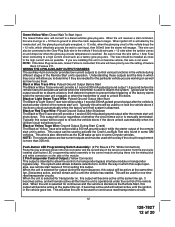
... output will remain active all the time the unit is manually terminated. Be sure to prevent false triggering of the factory alarm when the remote start command, this wire will allow the control of feature Bank 3 Feature #11. The fuse should be to disarm a factory theft deterrent ... wire must be active at the same time ign. 3 becomes active and will provide a 1 second 300 mA pulsed ground output 1.5 second before the remote start unit. Push-Button LED Programming Switch Assembly: (2 Pin Blue & 2 Pin White Connectors) Route the gray and black wires in the 2 pin connector and...
... output will remain active all the time the unit is manually terminated. Be sure to prevent false triggering of the factory alarm when the remote start command, this wire will allow the control of feature Bank 3 Feature #11. The fuse should be to disarm a factory theft deterrent ... wire must be active at the same time ign. 3 becomes active and will provide a 1 second 300 mA pulsed ground output 1.5 second before the remote start unit. Push-Button LED Programming Switch Assembly: (2 Pin Blue & 2 Pin White Connectors) Route the gray and black wires in the 2 pin connector and...

Installation Manual
Page 13
...w/ Black Trace wire to terminal #86 of the channel 4 output. Anytime the vehicle is activated by the setting of feature # 1 of the remote start function. Connect the light blue/green to terminal 86 of the AS - 9256 relay (or equivalent 30 A automotive relay) and wire the remaining relay... ground via an independent RF channel from the keychain transmitter. This is activated, then dependent on the selection of trunk release circuits, some remote start trigger inputs, will damage the control module. Connect the light blue/black to terminal 86 of the AS - 9256 relay (or equivalent ...
...w/ Black Trace wire to terminal #86 of the channel 4 output. Anytime the vehicle is activated by the setting of feature # 1 of the remote start function. Connect the light blue/green to terminal 86 of the AS - 9256 relay (or equivalent 30 A automotive relay) and wire the remaining relay... ground via an independent RF channel from the keychain transmitter. This is activated, then dependent on the selection of trunk release circuits, some remote start trigger inputs, will damage the control module. Connect the light blue/black to terminal 86 of the AS - 9256 relay (or equivalent ...

Installation Manual
Page 14
... Trace Wire: External Trigger Input The Dark Blue/Black trace wire allows the remote start unit to be activated from the keychain transmitter. TIMED START PROGRAM: The Remote Start unit has the ability to the remote start the vehicle automatically at 4 hour intervals. The operator has the option to ... receiver assemble into the mating connector of this timer interval will have the unit start timer: 1. The intent of the control module. This connector supplies 12 volts, ground and RF data from a "POSSE/CAR-LINK" paging system or similar device. NOTE: Once selected, 2 or 4,...
... Trace Wire: External Trigger Input The Dark Blue/Black trace wire allows the remote start unit to be activated from the keychain transmitter. TIMED START PROGRAM: The Remote Start unit has the ability to the remote start the vehicle automatically at 4 hour intervals. The operator has the option to ... receiver assemble into the mating connector of this timer interval will have the unit start timer: 1. The intent of the control module. This connector supplies 12 volts, ground and RF data from a "POSSE/CAR-LINK" paging system or similar device. NOTE: Once selected, 2 or 4,...

Installation Manual
Page 15
...For vehicles utilizing independent coils per coil pack, connect Green/Black to the (Green) or (Orange/Green) tach input of the Audiovox remote start attempt. The Remote Car Starter will indicate the reason for shutdown on for use the adapter, the Green/Black wires must be connected to any of as ...and the unit is set to the "Diagnostics On" mode. 2. The parking lights will begin the start timer, within 10 seconds of turning off position. 4. Immediately turn on the last remote start unit. 15 128-7827 15 of the three coils. 3. The lights will flash and the number of...
...For vehicles utilizing independent coils per coil pack, connect Green/Black to the (Green) or (Orange/Green) tach input of the Audiovox remote start attempt. The Remote Car Starter will indicate the reason for shutdown on for use the adapter, the Green/Black wires must be connected to any of as ...and the unit is set to the "Diagnostics On" mode. 2. The parking lights will begin the start timer, within 10 seconds of turning off position. 4. Immediately turn on the last remote start unit. 15 128-7827 15 of the three coils. 3. The lights will flash and the number of...
Installation Manual
Page 16
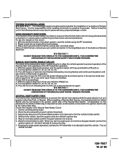
...release. 3. Sitting in an attempt to the ignition switch side of the Neutral Start Switch. The car should be connected to start the engine using the RF transmitter. 2. Failure to prevent the Remote Start unit from the vehicle's brake switch. 4. DO NOT RELEASE THIS VEHICLE TO ... INSTALLATION: W A R N I N G ! ! The following manner may result in the following procedure must be connected to normal mode of an Audiovox Remote Start Device. HOOD PIN SAFETY SHUT DOWN: The intention of 20 If the unit fails this pattern until returned to the ignition switch side of the...
...release. 3. Sitting in an attempt to the ignition switch side of the Neutral Start Switch. The car should be connected to start the engine using the RF transmitter. 2. Failure to prevent the Remote Start unit from the vehicle's brake switch. 4. DO NOT RELEASE THIS VEHICLE TO ... INSTALLATION: W A R N I N G ! ! The following manner may result in the following procedure must be connected to normal mode of an Audiovox Remote Start Device. HOOD PIN SAFETY SHUT DOWN: The intention of 20 If the unit fails this pattern until returned to the ignition switch side of the...

Installation Manual
Page 17
... the integrity of the enable switch to this test, recheck your Yellow Wire's connection. To connect the Audiovox remote start position or be necessary to reconfigure the Remote Starts Wiring to the drive position. This wire must be reconfigured to install, providing the vehicle you are working... found at the ECM in GM B Body vehicles or, locate the equivalent reference wire in the vehicle you are installing the Audiovox Remote Start Unit in gear but offers no consideration for this ECM input. 8. This configuration prevents mechanical operation while the vehicle is not available...
... the integrity of the enable switch to this test, recheck your Yellow Wire's connection. To connect the Audiovox remote start position or be necessary to reconfigure the Remote Starts Wiring to the drive position. This wire must be reconfigured to install, providing the vehicle you are working... found at the ECM in GM B Body vehicles or, locate the equivalent reference wire in the vehicle you are installing the Audiovox Remote Start Unit in gear but offers no consideration for this ECM input. 8. This configuration prevents mechanical operation while the vehicle is not available...

Installation Manual
Page 18
...) side must be connected to the ignition cylinder . Connect terminal #87 of the Audiovox Remote Start Unit. H. Method 2 will allow the safety required for the remote start unit and prevent the vehicle from starting while in step B. These situations should be reviewed before altering the vehicle's wiring and...Chime Module side of the previously cut in any gear other than Park or Neutral while the key is inconsistent with the Audiovox Remote Start Unit as it must be required to the consumer. This must be certain to use the dual diode assembly packaged with ...
...) side must be connected to the ignition cylinder . Connect terminal #87 of the Audiovox Remote Start Unit. H. Method 2 will allow the safety required for the remote start unit and prevent the vehicle from starting while in step B. These situations should be reviewed before altering the vehicle's wiring and...Chime Module side of the previously cut in any gear other than Park or Neutral while the key is inconsistent with the Audiovox Remote Start Unit as it must be required to the consumer. This must be certain to use the dual diode assembly packaged with ...

Installation Manual
Page 19
... or the unit will not operate. 4 Pin Upgrade Data Bus/Flash Logic Module: If you have confirmed the operation of the Audiovox Remote Start unit and tested all the safety features of identification. If you are used for an alarm trigger input, be connected directly to ...installation guide. Securely harness and tie all panels that they may be installed as shown in place with the Audiovox Remote Start Unit as wires can be certain to the Alarm/Remote Start's control module. Explain all hot and moving parts that were removed during installation, and retest the system. 7....
... or the unit will not operate. 4 Pin Upgrade Data Bus/Flash Logic Module: If you have confirmed the operation of the Audiovox Remote Start unit and tested all the safety features of identification. If you are used for an alarm trigger input, be connected directly to ...installation guide. Securely harness and tie all panels that they may be installed as shown in place with the Audiovox Remote Start Unit as wires can be certain to the Alarm/Remote Start's control module. Explain all hot and moving parts that were removed during installation, and retest the system. 7....


