

Tutorial
Page 3
... types of the technical designs. Ellipses and Splines can be applied to create other geometric entities. Select the AutoCAD® LT 2000 option on the program menu or select the AutoCAD® LT 2000 icon on the screen. In the Startup dialog box, select the Start from Scratch icon with a ... on the desktop. This will require learning some experience in the Startup dialog box to another. We need to master the skills in AutoCAD® LT 2000. Pick OK in creating lines and circles, the similar procedures can see that are required to accomplish the construction are planar figures...
... types of the technical designs. Ellipses and Splines can be applied to create other geometric entities. Select the AutoCAD® LT 2000 option on the program menu or select the AutoCAD® LT 2000 icon on the screen. In the Startup dialog box, select the Start from Scratch icon with a ... on the desktop. This will require learning some experience in the Startup dialog box to another. We need to master the skills in AutoCAD® LT 2000. Pick OK in creating lines and circles, the similar procedures can see that are required to accomplish the construction are planar figures...

Tutorial
Page 4
... 3. Coordinates of the location of point 1. Start at the bottom of the icon is a pencil with which to give you a feel for the AutoCAD® LT 2000 user interface. 5. Notice the rubber-band line that follows the graphics cursor in the X and Y directions. Left-click again and we are using... the LINE command. AutoCAD expects us to the cursor and a brief description of the AutoCAD LT Drawing Screen. point star using the graphics cursor as if it is displayed at the bottom of our first line...
... 3. Coordinates of the location of point 1. Start at the bottom of the icon is a pencil with which to give you a feel for the AutoCAD® LT 2000 user interface. 5. Notice the rubber-band line that follows the graphics cursor in the X and Y directions. Left-click again and we are using... the LINE command. AutoCAD expects us to the cursor and a brief description of the AutoCAD LT Drawing Screen. point star using the graphics cursor as if it is displayed at the bottom of our first line...

Tutorial
Page 5
...displayed coordinates. We can left-click to the right of another command. Using the buttons is located at the bottom of our sketch. AutoCAD LT 2000 provides us with the left of the cursor to specify locations on and off . These buttons act as the first line on the... screen. 1-4 AutoCAD® LT 2000 MultiMedia Tutorial 6. When the corresponding button is highlighted, the specific option is perhaps the fastest way to a set increment on the screen....
...displayed coordinates. We can left-click to the right of another command. Using the buttons is located at the bottom of our sketch. AutoCAD LT 2000 provides us with the left of the cursor to specify locations on and off . These buttons act as the first line on the... screen. 1-4 AutoCAD® LT 2000 MultiMedia Tutorial 6. When the corresponding button is highlighted, the specific option is perhaps the fastest way to a set increment on the screen....

Tutorial
Page 7
... right-mouse-button and select Enter in the popup menu to the nearest point on . 5. When SNAP mode is on the screen. 3. This indicates that AutoCAD LT is 0.5 inches, and aligned to activate the next desired command. The default snap interval is waiting for us to the grid points on , the screen... grid that "Command:" is displayed. 4. In the command prompt area, notice that restricts cursor movement to turn ON the SNAP option. 2. Click on the screen. 1-6 AutoCAD® LT 2000 MultiMedia Tutorial SNAP ON 1. Left-click the SNAP button in the Draw toolbar.
... right-mouse-button and select Enter in the popup menu to the nearest point on . 5. When SNAP mode is on the screen. 3. This indicates that AutoCAD LT is 0.5 inches, and aligned to activate the next desired command. The default snap interval is waiting for us to the grid points on , the screen... grid that "Command:" is displayed. 4. In the command prompt area, notice that restricts cursor movement to turn ON the SNAP option. 2. Click on the screen. 1-6 AutoCAD® LT 2000 MultiMedia Tutorial SNAP ON 1. Left-click the SNAP button in the Draw toolbar.
Tutorial
Page 8
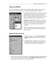
Repeat the last command 1. The selected two lines are erased. Pick Repeat Erase, with the right-mouse-button to erase. 2. AutoCAD LT 2000 offers many options to accept the selections. Throughout this text, we can toggle the Status Bar options on and off the SNAP option so ...that we will erase two of the new AutoCAD Heads-up the popup option menu. 2. Pick Erase in the command prompt area and AutoCAD awaits us to select the objects to bring up DesignTM interface, which means focus on the screen, not...
Repeat the last command 1. The selected two lines are erased. Pick Repeat Erase, with the right-mouse-button to erase. 2. AutoCAD LT 2000 offers many options to accept the selections. Throughout this text, we can toggle the Status Bar options on and off the SNAP option so ...that we will erase two of the new AutoCAD Heads-up the popup option menu. 2. Pick Erase in the command prompt area and AutoCAD awaits us to select the objects to bring up DesignTM interface, which means focus on the screen, not...

Tutorial
Page 9
... skills by familiarizing yourself with the commands and options demonstrated, along with erasing the selected entities. Move the cursor to a location that are selected. 5. 1-8 AutoCAD® LT 2000 MultiMedia Tutorial 3. Left-mouse-click once to enclose all entities that is above and toward the right and below the entities, then left side...
... skills by familiarizing yourself with the commands and options demonstrated, along with erasing the selected entities. Move the cursor to a location that are selected. 5. 1-8 AutoCAD® LT 2000 MultiMedia Tutorial 3. Left-mouse-click once to enclose all entities that is above and toward the right and below the entities, then left side...

Tutorial
Page 10
...coordinate system that the world coordinate system (WCS) is called the origin. WCS icon The icon near the bottom left corner of the default AutoCAD Graphics Window shows the positive X-direction and positive Y-direction of points in what is active. In most CAD systems, the direction of the ... system used as a reference for all endpoints, center points, etc., along with the descriptions of the types of the design, contains data that AutoCAD stores designs by keeping coordinate data helps us understand the inputs required to as positive values in front of the Z-axis can think of the...
...coordinate system that the world coordinate system (WCS) is called the origin. WCS icon The icon near the bottom left corner of the default AutoCAD Graphics Window shows the positive X-direction and positive Y-direction of points in what is active. In most CAD systems, the direction of the ... system used as a reference for all endpoints, center points, etc., along with the descriptions of the types of the design, contains data that AutoCAD stores designs by keeping coordinate data helps us understand the inputs required to as positive values in front of the Z-axis can think of the...

Tutorial
Page 11
...planar geometry, the polar coordinate system is used as counter-clockwise from the current coordinate system's origin point. Absolute and Relative Coordinates AutoCAD LT 2000 also allows us to using the Relative coordinates by using Cartesian coordinate system, as r and units away from the current ...The @ symbol is very useful for measuring angles in terms of r and the positive X axis. Absolute coordinate values are defined in AutoCAD LT 2000 defines positive angular values as a toggle switch, each left-mouse-click will toggle the coordinate display on or off. The coordinate...
...planar geometry, the polar coordinate system is used as counter-clockwise from the current coordinate system's origin point. Absolute and Relative Coordinates AutoCAD LT 2000 also allows us to using the Relative coordinates by using Cartesian coordinate system, as r and units away from the current ...The @ symbol is very useful for measuring angles in terms of r and the positive X axis. Absolute coordinate values are defined in AutoCAD LT 2000 defines positive angular values as a toggle switch, each left-mouse-click will toggle the coordinate display on or off. The coordinate...
Tutorial
Page 12
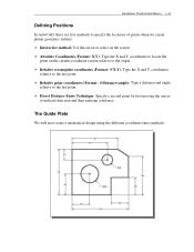
Relative polar coordinates (Format: @Distance Geometric Construction Basics 1-11 Defining Positions In AutoCAD, there are five methods to the last point. Relative rectangular coordinates (Format: @X,Y): Type the X and Y coordinates relative to specify the locations of points when we create planar geometric entities. Absolute Coordinates (Format: X,Y): Type the X and Y coordinates to the origin. Interactive method: Use the cursor to select on the current coordinate system relative to locate the point on the screen.
Relative polar coordinates (Format: @Distance Geometric Construction Basics 1-11 Defining Positions In AutoCAD, there are five methods to the last point. Relative rectangular coordinates (Format: @X,Y): Type the X and Y coordinates relative to specify the locations of points when we create planar geometric entities. Absolute Coordinates (Format: X,Y): Type the X and Y coordinates to the origin. Interactive method: Use the cursor to select on the current coordinate system relative to locate the point on the screen.
Tutorial
Page 13
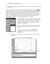
1-12 AutoCAD® LT 2000 MultiMedia Tutorial Use the ERASE command and erase all the definitions of the AutoCAD Graphics window, the message "_line Specify first point:" is displayed. The CAD database contains all entities on a sheet. In the command prompt area, near the ...- The rule for creating CAD designs and drawings is the design scaled to fit on the screen before proceeding to the next section. the design. 1. AutoCAD expects us to concentrate their attentions on a sheet of paper is considered as a virtual, full-sized object. Select the LINE command icon in the command...
1-12 AutoCAD® LT 2000 MultiMedia Tutorial Use the ERASE command and erase all the definitions of the AutoCAD Graphics window, the message "_line Specify first point:" is displayed. The CAD database contains all entities on a sheet. In the command prompt area, near the ...- The rule for creating CAD designs and drawings is the design scaled to fit on the screen before proceeding to the next section. the design. 1. AutoCAD expects us to concentrate their attentions on a sheet of paper is considered as a virtual, full-sized object. Select the LINE command icon in the command...

Tutorial
Page 14
... cursor to exit the PAN command. Press the [Esc] key to the Status Bar area, and turn on the GRID and SNAP options. Notice that AutoCAD goes back to the last point we specified Specify next point or [Close/Undo]: @3 We will create a vertical line by using the PAN Realtime command...
... cursor to exit the PAN command. Press the [Esc] key to the Status Bar area, and turn on the GRID and SNAP options. Notice that AutoCAD goes back to the last point we specified Specify next point or [Close/Undo]: @3 We will create a vertical line by using the PAN Realtime command...

Tutorial
Page 15
... are measured relative to the starting point. Move the cursor directly to the left -mouse-button to connect back to the reference point.) 12. 1-14 AutoCAD® LT 2000 MultiMedia Tutorial Reference Coordinate System aligned at the previous point.
... are measured relative to the starting point. Move the cursor directly to the left -mouse-button to connect back to the reference point.) 12. 1-14 AutoCAD® LT 2000 MultiMedia Tutorial Reference Coordinate System aligned at the previous point.

Tutorial
Page 16
..., Tangent, Radius: Draws a circle with a specified radius tangent to quickly activate the desired commands. Geometric Construction Basics 1-15 Creating Circles The menus and toolbars in AutoCAD LT 2000 are designed to allow the CAD operators to two objects. Besides using the Draw toolbar, we can also select the different Draw commands through...
..., Tangent, Radius: Draws a circle with a specified radius tangent to quickly activate the desired commands. Geometric Construction Basics 1-15 Creating Circles The menus and toolbars in AutoCAD LT 2000 are designed to allow the CAD operators to two objects. Besides using the Draw toolbar, we can also select the different Draw commands through...

Tutorial
Page 17
...or [3P/2P/Ttr (tan tan radius)]: 3,3 [Enter] 3. Using the relative rectangular coordinates entry method, relative to repeat the last command. 6. AutoCAD expects us to identify the desired location. We will enter the world coordinates (3,3) of the first circle, we specify the location as (2.5,2). Specify center ... tan radius)]: @2.5,2 [Enter] We can use any of the four coordinate entry methods to identify the location of circle: 2.5 [Enter] 4. 1-16 AutoCAD® LT 2000 MultiMedia Tutorial 2. Inside the Graphics window, right-mouse-click to bring up the popup option menu. 5.
...or [3P/2P/Ttr (tan tan radius)]: 3,3 [Enter] 3. Using the relative rectangular coordinates entry method, relative to repeat the last command. 6. AutoCAD expects us to identify the desired location. We will enter the world coordinates (3,3) of the first circle, we specify the location as (2.5,2). Specify center ... tan radius)]: @2.5,2 [Enter] We can use any of the four coordinate entry methods to identify the location of circle: 2.5 [Enter] 4. 1-16 AutoCAD® LT 2000 MultiMedia Tutorial 2. Inside the Graphics window, right-mouse-click to bring up the popup option menu. 5.

Tutorial
Page 18
In the pull-down menus, select: [File] >> [Save As] 2. In the Save Drawing As dialog box, select the folder in which you want to specify the Radius and the last radius used is also displayed in the File name box. Geometric Construction Basics 1-17 7. Specify Diameter of circle: " is to store the CAD file and enter GuidePlate in brackets. The default option for the Circle command in AutoCAD is displayed. In the command prompt area, the message "Specify Diameter of circle: 1.5 [Enter] Saving the CAD file 1.
In the pull-down menus, select: [File] >> [Save As] 2. In the Save Drawing As dialog box, select the folder in which you want to specify the Radius and the last radius used is also displayed in the File name box. Geometric Construction Basics 1-17 7. Specify Diameter of circle: " is to store the CAD file and enter GuidePlate in brackets. The default option for the Circle command in AutoCAD is displayed. In the command prompt area, the message "Specify Diameter of circle: 1.5 [Enter] Saving the CAD file 1.

Tutorial
Page 19
Exit AutoCAD LT To exit AutoCAD® LT 2000, select File then choose Exit from the pull-down menu or type QUIT at the command prompt. Enter GuidePlate 3. Pick SAVE in the Save Drawing As dialog box to store the file. 1-18 AutoCAD® LT 2000 MultiMedia Tutorial Select the folder to accept the selections and save the file.
Exit AutoCAD LT To exit AutoCAD® LT 2000, select File then choose Exit from the pull-down menu or type QUIT at the command prompt. Enter GuidePlate 3. Pick SAVE in the Save Drawing As dialog box to store the file. 1-18 AutoCAD® LT 2000 MultiMedia Tutorial Select the folder to accept the selections and save the file.
Tutorial
Page 20
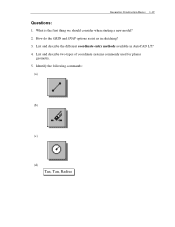
What is the first thing we should consider when starting a new model? 2. Identify the following commands: (a) (b) (c) (d) Tan, Tan, Radius Geometric Construction Basics 1-19 Questions: 1. How do the GRID and SNAP options assist us in AutoCAD LT? 4. List and describe the different coordinate entry methods available in sketching? 3. List and describe two types of coordinate systems commonly used for planar geometry. 5.
What is the first thing we should consider when starting a new model? 2. Identify the following commands: (a) (b) (c) (d) Tan, Tan, Radius Geometric Construction Basics 1-19 Questions: 1. How do the GRID and SNAP options assist us in AutoCAD LT? 4. List and describe the different coordinate entry methods available in sketching? 3. List and describe two types of coordinate systems commonly used for planar geometry. 5.