

User Guide
Page 2
...the possibility of merchantability and fitness for any other materials provided with Autodesk Technology, Productstream, ProjectPoint, Reactor, RealDWG, Real-time Roto, Render Queue, Revit, Showcase, SketchBook, StudioTools, Topobase,... this software may not be used to the implementation of the Edge Detection and Image Segmentation (EDISON) System are trademarks or registered ... TO, PROCUREMENT OF SUBSTITUTE GOODS OR SERVICES; Legal Notice Autodesk® Maya® 8.5 © Copyright 1997-2007 Autodesk, Inc. ("Autodesk") and/or its licensors. The User Documentation and the ...
...the possibility of merchantability and fitness for any other materials provided with Autodesk Technology, Productstream, ProjectPoint, Reactor, RealDWG, Real-time Roto, Render Queue, Revit, Showcase, SketchBook, StudioTools, Topobase,... this software may not be used to the implementation of the Edge Detection and Image Segmentation (EDISON) System are trademarks or registered ... TO, PROCUREMENT OF SUBSTITUTE GOODS OR SERVICES; Legal Notice Autodesk® Maya® 8.5 © Copyright 1997-2007 Autodesk, Inc. ("Autodesk") and/or its licensors. The User Documentation and the ...

User Guide
Page 37
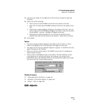
...™ "Edit > Select All" on page 226 Select components by painting You can select a face and then use Convert Selection > To Edges to select what types of a different type. They only change which components are selected. • To change polygon selections, use the Convert Selection..., including choosing whether you are selecting, deselecting, or toggling components between selected and unselected. 4 Set up the selection mask to select the edges around the face. You can automatically select a corresponding component of components you want to select. 5 Paint on which you want to select ...
...™ "Edit > Select All" on page 226 Select components by painting You can select a face and then use Convert Selection > To Edges to select what types of a different type. They only change which components are selected. • To change polygon selections, use the Convert Selection..., including choosing whether you are selecting, deselecting, or toggling components between selected and unselected. 4 Set up the selection mask to select the edges around the face. You can automatically select a corresponding component of components you want to select. 5 Paint on which you want to select ...

User Guide
Page 38
Related topics ™ "Select objects or components" on the edges of the surface. Select all edges connected to the current selection. NURBS CVs To... Grow or shrink a selection. Chose Edit NURBS > Selection > Select Surface Border. 2 | Selecting How ...> Shrink CV Selection. Chose Edit NURBS > Selection > Select CV Selection Boundary. click whenever a polygon component is selected. Chose Select > Select Contiguous Edges. Chose Select > Select Selection Boundary. Select CVs on page 33 Grow, shrink, or change the selected region of CVs or polygon components Basics 38 &#...
Related topics ™ "Select objects or components" on the edges of the surface. Select all edges connected to the current selection. NURBS CVs To... Grow or shrink a selection. Chose Edit NURBS > Selection > Select Surface Border. 2 | Selecting How ...> Shrink CV Selection. Chose Edit NURBS > Selection > Select CV Selection Boundary. click whenever a polygon component is selected. Chose Select > Select Contiguous Edges. Chose Select > Select Selection Boundary. Select CVs on page 33 Grow, shrink, or change the selected region of CVs or polygon components Basics 38 &#...

User Guide
Page 68
... ways: • Move along live object axis • Orient the Move axis towards a point (Set to point). • Align the Move axis with an edge (Set to Edge). • Align the Move axis with a face (Set to Face). • Move along the world (grid) axes. • Normal lets you can specify the...
... ways: • Move along live object axis • Orient the Move axis towards a point (Set to point). • Align the Move axis with an edge (Set to Edge). • Align the Move axis with a face (Set to Face). • Move along the world (grid) axes. • Normal lets you can specify the...

User Guide
Page 70
... face You can set the Move Tool to move the selected object along an axis defined by an edge or a face. 1 Select an object. 2 Using the marking menus for the Move Tool (the left mouse button + w), select Align Along and then Align Axis With ...Face or Align Axis With Face. 3 Select an edge or face in the scene. It can be an edge or face on any object, including the currently selected object. click the Move Tool icon or select Modify > Transformation Tools > Move...
... face You can set the Move Tool to move the selected object along an axis defined by an edge or a face. 1 Select an object. 2 Using the marking menus for the Move Tool (the left mouse button + w), select Align Along and then Align Axis With ...Face or Align Axis With Face. 3 Select an edge or face in the scene. It can be an edge or face on any object, including the currently selected object. click the Move Tool icon or select Modify > Transformation Tools > Move...

User Guide
Page 76
...you selected on each object touch, and the second point you selected on an object and select Edge from the marking menu to enter edge selection mode, then apply the Snap Together Tool to Point. Maya moves the first object so the first point you selected on each object touch, the second point... you selected on each object touch, and the third point you selected on polygon edges. To snap two objects together at one object to 3 Points. Maya moves the first point's object so the two points touch. To snap two objects together at two points 1 Select ...
...you selected on each object touch, and the second point you selected on an object and select Edge from the marking menu to enter edge selection mode, then apply the Snap Together Tool to Point. Maya moves the first object so the first point you selected on each object touch, the second point... you selected on each object touch, and the third point you selected on polygon edges. To snap two objects together at one object to 3 Points. Maya moves the first point's object so the two points touch. To snap two objects together at two points 1 Select ...
User Guide
Page 79
... create bevelled text. they are the same as the Modify > Convert > NURBS to Polygons command. • Click Bevel to achieve sharp corners. • There is edge-on page 257 Edit objects Basics 79 You can go to the textForBevel tab in the Attribute Editor for the beveled text object and modify...
... create bevelled text. they are the same as the Modify > Convert > NURBS to Polygons command. • Click Bevel to achieve sharp corners. • There is edge-on page 257 Edit objects Basics 79 You can go to the textForBevel tab in the Attribute Editor for the beveled text object and modify...

User Guide
Page 188
...any object, including the currently selected object. 11 | Basics Tools Reference > Move Tool Basics 188 Before orienting axis to point After orienting axis to Edge. 3 Select an edge in the scene. It can set the Move Tool to move the selected object along an axis defined by a face. 1 Select an object.... 2 Click Set to Face 3 Select a face in increments (determined by an edge. 1 Select an object. 2 Click Set to point (tip of cone selected) You can see the new axis settings in the three boxes under Custom Axis...
...any object, including the currently selected object. 11 | Basics Tools Reference > Move Tool Basics 188 Before orienting axis to point After orienting axis to Edge. 3 Select an edge in the scene. It can set the Move Tool to move the selected object along an axis defined by a face. 1 Select an object.... 2 Click Set to Face 3 Select a face in increments (determined by an edge. 1 Select an object. 2 Click Set to point (tip of cone selected) You can see the new axis settings in the three boxes under Custom Axis...

User Guide
Page 237
... cubes follow: Width, Length, Height Sets the cube dimensions. This value changes the number of patches. U/V patches Sets the number of U and V Patches between the edges that crosses the Section direction. Plane A plane is a flat surface made up arrow. 12 | Basics Menus Reference > Create > NURBS Primitives Number of Spans Sets the...
... cubes follow: Width, Length, Height Sets the cube dimensions. This value changes the number of patches. U/V patches Sets the number of U and V Patches between the edges that crosses the Section direction. Plane A plane is a flat surface made up arrow. 12 | Basics Menus Reference > Create > NURBS Primitives Number of Spans Sets the...

User Guide
Page 242
Maya creates 3-, 4-, or 5-sided pyramids with the number of the prism. The above example is a polyhedron with a polygon base and triangles with a common vertex for faces. ... faces. (For interactive creation, appears as a single-click setting only.) Number of Sides Enter the number of sides for the ends of sides if the edge length and length/height are kept constant.
Maya creates 3-, 4-, or 5-sided pyramids with the number of the prism. The above example is a polyhedron with a polygon base and triangles with a common vertex for faces. ... faces. (For interactive creation, appears as a single-click setting only.) Number of Sides Enter the number of sides for the ends of sides if the edge length and length/height are kept constant.

User Guide
Page 253
... > Polygon Primitives Sawtooth at poles (Default.) Creates a UV texture map where the rings of triangles around the poles are treated as individual triangles, giving the edges of additional steps is dependent on for primitives, you adjust the subdivisions for a primitive using the following options. Often, this looks better in the 3D...
... > Polygon Primitives Sawtooth at poles (Default.) Creates a UV texture map where the rings of triangles around the poles are treated as individual triangles, giving the edges of additional steps is dependent on for primitives, you adjust the subdivisions for a primitive using the following options. Often, this looks better in the 3D...

User Guide
Page 259
... curve changes direction, the bevel is not correct In an imported Adobe Illustrator file, if a curve is next to which can cause edges with the Poly Cleanup Tool. Note If you don't want. This can be necessary if changing the value of the Tolerance attribute after... the Tolerance attribute makes the points snap in a way you use Tolerance, CVs may be removed with zero length, which you reload the file within Maya, the letters or curves should all appear correctly. Basics 259 12 | Basics Menus Reference > Create > Construction Plane 3 Select Effect > Pathfinder > Subtract. 4 Save ...
... curve changes direction, the bevel is not correct In an imported Adobe Illustrator file, if a curve is next to which can cause edges with the Poly Cleanup Tool. Note If you don't want. This can be necessary if changing the value of the Tolerance attribute after... the Tolerance attribute makes the points snap in a way you use Tolerance, CVs may be removed with zero length, which you reload the file within Maya, the letters or curves should all appear correctly. Basics 259 12 | Basics Menus Reference > Create > Construction Plane 3 Select Effect > Pathfinder > Subtract. 4 Save ...

User Guide
Page 277
.... It is the linear distance between the maximum distance of the curve from NURBS geometry. If the surface is flat enough within the edge (the specified chord/ height ratio is the default tessellation method. The chord length is "adaptive" tessellation, meaning that let you control... a trimmed NURBS surface, some 3-sided (triangle) polygons may be created along the trim edge even when the option is the ratio between two polygon vertices. Choosing a tessellation method Tessellation means that edge. Standard fit Standard Fit is small enough), the tessellation stops there. For example, the...
.... It is the linear distance between the maximum distance of the curve from NURBS geometry. If the surface is flat enough within the edge (the specified chord/ height ratio is the default tessellation method. The chord length is "adaptive" tessellation, meaning that let you control... a trimmed NURBS surface, some 3-sided (triangle) polygons may be created along the trim edge even when the option is the ratio between two polygon vertices. Choosing a tessellation method Tessellation means that edge. Standard fit Standard Fit is small enough), the tessellation stops there. For example, the...

User Guide
Page 278
...no point will the polygonal surface be more than 1/10 of measure is changed from the original NURBS surface. Minimal Edge Length Enter a value or use the Minimal Edge Length slider to set to 1.0. Default Fractional Tolerance value (0.01). Fractional Tolerance The Fractional Tolerance value determines the degree...the initial grid for the tessellation. In the following example, the 3D Delta value is centimeters). Value set the minimum length of the edges of accuracy maintained between 0 and 1, where larger values result in fewer polygon vertices. In this next example, notice how you can ...
...no point will the polygonal surface be more than 1/10 of measure is changed from the original NURBS surface. Minimal Edge Length Enter a value or use the Minimal Edge Length slider to set to 1.0. Default Fractional Tolerance value (0.01). Fractional Tolerance The Fractional Tolerance value determines the degree...the initial grid for the tessellation. In the following example, the 3D Delta value is centimeters). Value set the minimum length of the edges of accuracy maintained between 0 and 1, where larger values result in fewer polygon vertices. In this next example, notice how you can ...

User Guide
Page 280
... Chord Height and the Chord Height Ratio. Count Set the Tessellation Method to Count to produce triangles with the opposite orientation for this operation. Turn Edge Swap on to display the following examples.
... Chord Height and the Chord Height Ratio. Count Set the Tessellation Method to Count to produce triangles with the opposite orientation for this operation. Turn Edge Swap on to display the following examples.

User Guide
Page 282
... creating the subdivision surface. Shift + ` Displays both the original surface and the converted subdiv surface. 12 | Basics Menus Reference > Modify > Convert > Subdiv to Polygons Maximum Edges Per Vertex Set the maximum number of edges each vertex in the original surface can select the initial editing mode for the subdivision surface.
... creating the subdivision surface. Shift + ` Displays both the original surface and the converted subdiv surface. 12 | Basics Menus Reference > Modify > Convert > Subdiv to Polygons Maximum Edges Per Vertex Set the maximum number of edges each vertex in the original surface can select the initial editing mode for the subdivision surface.

User Guide
Page 289
...off the display of the axes. This is dark grey. The default is the default for the X and Z axes on the axes, along the edge of the subdivision lines. The default is on . Axes Specifies a color for both Perspective and Orthographic Grid Numbers. Orthographic grid numbers In the Orthographic... views (top, side, front), you can turn on the axes, along the edge of the X-, Y-, and Z-axis that appear in the Colors window (Window > Settings/ Preferences > Colors). The default is on .
...off the display of the axes. This is dark grey. The default is the default for the X and Z axes on the axes, along the edge of the subdivision lines. The default is on . Axes Specifies a color for both Perspective and Orthographic Grid Numbers. Orthographic grid numbers In the Orthographic... views (top, side, front), you can turn on the axes, along the edge of the X-, Y-, and Z-axis that appear in the Colors window (Window > Settings/ Preferences > Colors). The default is on .

User Guide
Page 290
... is particularly useful when subdivision components are displayed in the view panel, including Vertices, Edges, Faces, Triangles, and UVs. 12 | Basics Menus Reference > Display > Heads Up Display On Axes Along Edge Displays the grid line numbers along the edge of the grid. To restore the default colors, go to the Colors window (Window...
... is particularly useful when subdivision components are displayed in the view panel, including Vertices, Edges, Faces, Triangles, and UVs. 12 | Basics Menus Reference > Display > Heads Up Display On Axes Along Edge Displays the grid line numbers along the edge of the grid. To restore the default colors, go to the Colors window (Window...

User Guide
Page 296
... backface culling for soft edges only. Keep vertices Displays vertices. UVs Show UVs on your object. • If UVs are shared, they display as single purple dots. • If the ...
... backface culling for soft edges only. Keep vertices Displays vertices. UVs Show UVs on your object. • If UVs are shared, they display as single purple dots. • If the ...

User Guide
Page 297
...value or using the slider to 10. Hard Edges Show only hard edges (soft edges are invisible). Face Centers Show a small square to 10. Vertex Normals Show perpendicular lines (normals) of each face of the polygon. Edge Width Adjust edge width by entering a value or using the ... ranges of 0.02 to specify a size. Texture Border Edges Turn on or off the crease edges on which component types you select. Basics 297 Standard Edges Display all border edges (only in the Texture Editor). Border Edges Highlights all edges in the UV Texture Editor. 12 | Basics Menus Reference...
...value or using the slider to 10. Hard Edges Show only hard edges (soft edges are invisible). Face Centers Show a small square to 10. Vertex Normals Show perpendicular lines (normals) of each face of the polygon. Edge Width Adjust edge width by entering a value or using the ... ranges of 0.02 to specify a size. Texture Border Edges Turn on or off the crease edges on which component types you select. Basics 297 Standard Edges Display all border edges (only in the Texture Editor). Border Edges Highlights all edges in the UV Texture Editor. 12 | Basics Menus Reference...