
Setup Manual
Page 3
...please make sure you follow the instructions below: „ Prepare a dry and stable working environment with sufficient lighting. „ Always disconnect the computer from power outlet before operation. „ Before you for ATX Case X 1 Installation Guide X 1 Fully Setup Driver CD X 1 (full version manual files ... our product. Hold the board on motherboard or the rear side of the board unless necessary. CHAPTER 1: INTRODUCTION N68S3B 1.1 BEFORE YOU START Thank you take the motherboard out from anti-static bag, ground yourself properly by area or your motherboard version. 1
...please make sure you follow the instructions below: „ Prepare a dry and stable working environment with sufficient lighting. „ Always disconnect the computer from power outlet before operation. „ Before you for ATX Case X 1 Installation Guide X 1 Fully Setup Driver CD X 1 (full version manual files ... our product. Hold the board on motherboard or the rear side of the board unless necessary. CHAPTER 1: INTRODUCTION N68S3B 1.1 BEFORE YOU START Thank you take the motherboard out from anti-static bag, ground yourself properly by area or your motherboard version. 1

Setup Manual
Page 4
... 1 SATA devices Front Panel Connector x1 Supports front panel facilities Front Audio Connector x1 Supports front panel audio function CPU Fan header x1 CPU Fan power supply (with Smart Fan function) System Fan header x1 System Fan...
... 1 SATA devices Front Panel Connector x1 Supports front panel facilities Front Audio Connector x1 Supports front panel audio function CPU Fan header x1 CPU Fan power supply (with Smart Fan function) System Fan header x1 System Fan...

Setup Manual
Page 5
...(L) Special Features RAID 0 / 1 OS Support Windows XP / Vista / 7 N68S3B SPEC x1 Restore CMOS data to factory default x2 Each connector supports 2 front panel USB ports x1 Connects to Power supply x1 Connects to Power supply x1 Each connector supports 1 Printer port x1 Connects to PS/2 Keyboard x1 ...Connects to PS/2 Mouse x1 Connect to D-SUB monitor x1 Connect to RJ-45 ethernet cable x4 Connect to USB devices x3 Provide Audio-In/Out and microphone connection uATX Biostar...
...(L) Special Features RAID 0 / 1 OS Support Windows XP / Vista / 7 N68S3B SPEC x1 Restore CMOS data to factory default x2 Each connector supports 2 front panel USB ports x1 Connects to Power supply x1 Connects to Power supply x1 Each connector supports 1 Printer port x1 Connects to PS/2 Keyboard x1 ...Connects to PS/2 Mouse x1 Connect to D-SUB monitor x1 Connect to RJ-45 ethernet cable x4 Connect to USB devices x3 Provide Audio-In/Out and microphone connection uATX Biostar...

Setup Manual
Page 8
Connect the CPU FAN power cable to complete the installation. This completes the installation. 6 Motherboard Manual Step 3: Hold the CPU down firmly, and then close the lever toward direct B to the JCFAN. Step 4: Put the CPU Fan on the CPU and buckle it.
Connect the CPU FAN power cable to complete the installation. This completes the installation. 6 Motherboard Manual Step 3: Hold the CPU down firmly, and then close the lever toward direct B to the JCFAN. Step 4: Put the CPU Fan on the CPU and buckle it.

Setup Manual
Page 12
The IDE connector can connect a master and a slave drive, so you can connect up to two drives. 40 39 21 JATXPWR4: ATX Power Source Connector This connect provides +12V to CPU power circuit. 4 3 1 2 Pin Assignment 1 +12V 2 +12V 3 Ground 4 Ground 10 Motherboard Manual 2.4 CONNECTORS AND SLOTS IDE: IDE/ATAPI Connector The motherboard has a 32-bit Enhanced PCI IDE Controller that provides PIO Mode 0~4, Bus Master, and Ultra DMA 33/66/100/133 functionality.
The IDE connector can connect a master and a slave drive, so you can connect up to two drives. 40 39 21 JATXPWR4: ATX Power Source Connector This connect provides +12V to CPU power circuit. 4 3 1 2 Pin Assignment 1 +12V 2 +12V 3 Ground 4 Ground 10 Motherboard Manual 2.4 CONNECTORS AND SLOTS IDE: IDE/ATAPI Connector The motherboard has a 32-bit Enhanced PCI IDE Controller that provides PIO Mode 0~4, Bus Master, and Ultra DMA 33/66/100/133 functionality.

Setup Manual
Page 13
N68S3B JATXPWR1: ATX Power Source Connector This connector allows user to connect 24-pin power connector on the ATX power supply. 12 24 1 13 Pin Assignment 13 +3.3V 14 -12V 15 Ground 16 PS_ON 17 Ground 18 Ground 19 Ground 20 NC 21 +5V 22 +5V 23 +5V 24 Ground Pin Assignment 1 +3.3V 2 +3.3V 3 Ground 4 +5V 5 Ground 6 +5V 7 Ground 8 PW_OK 9 Standby Voltage+5V 10 +12V 11 +12V 12 +3.3V Note: Before you power on the system, please make sure that both JATXPWR1 and JATXPWR4 connectors have been plugged-in. 11
N68S3B JATXPWR1: ATX Power Source Connector This connector allows user to connect 24-pin power connector on the ATX power supply. 12 24 1 13 Pin Assignment 13 +3.3V 14 -12V 15 Ground 16 PS_ON 17 Ground 18 Ground 19 Ground 20 NC 21 +5V 22 +5V 23 +5V 24 Ground Pin Assignment 1 +3.3V 2 +3.3V 3 Ground 4 +5V 5 Ground 6 +5V 7 Ground 8 PW_OK 9 Standby Voltage+5V 10 +12V 11 +12V 12 +3.3V Note: Before you power on the system, please make sure that both JATXPWR1 and JATXPWR4 connectors have been plugged-in. 11

Setup Manual
Page 15
... 10 Connector 11 12 Hard drive 13 LED 14 Reset button 15 16 Assignment N/A N/A N/A Power LED (+) Power LED (+) Power LED (-) Power button Ground Function N/A N/A Power LED Power-on , Reset, HDD LED, Power LED, Sleep, and speaker connection. It allows user to set up jumpers. When the jumper ...cap is placed on pins, the jumper is "close", if not, that means the jumper is "open". N68S3B ...
... 10 Connector 11 12 Hard drive 13 LED 14 Reset button 15 16 Assignment N/A N/A N/A Power LED (+) Power LED (+) Power LED (-) Power button Ground Function N/A N/A Power LED Power-on , Reset, HDD LED, Power LED, Sleep, and speaker connection. It allows user to set up jumpers. When the jumper ...cap is placed on pins, the jumper is "close", if not, that means the jumper is "open". N68S3B ...

Setup Manual
Page 17
...Front Sense 8 Key 9 Left line in 2 1 0 10 Jack Sense 1 9 JCMOS1: Clear CMOS Header By placing the jumper on the AC. 6. Wait for five seconds. 4. Power on pin2-3, it allows user to restore the BIOS safe setting and the CMOS data, please carefully follow the procedures to "Pin 2-3 close ". 5. Set the...(default). 31 3 1 Pin 2-3 Close: Clear CMOS data. ※ Clear CMOS Procedures: 1. Reset your desired password or clear the CMOS data. 15 Remove AC power line. 2. AC'97 connector is not acceptable. Set the jumper to connect the front audio output cable with the PC front panel...
...Front Sense 8 Key 9 Left line in 2 1 0 10 Jack Sense 1 9 JCMOS1: Clear CMOS Header By placing the jumper on the AC. 6. Wait for five seconds. 4. Power on pin2-3, it allows user to restore the BIOS safe setting and the CMOS data, please carefully follow the procedures to "Pin 2-3 close ". 5. Set the...(default). 31 3 1 Pin 2-3 Close: Clear CMOS data. ※ Clear CMOS Procedures: 1. Reset your desired password or clear the CMOS data. 15 Remove AC power line. 2. AC'97 connector is not acceptable. Set the jumper to connect the front audio output cable with the PC front panel...

Setup Manual
Page 18
Motherboard Manual JPRNT: Printer Port Connector This header allows you to connect printer port on the PC. 2 26 1 25 Pin Assignment 1 -Strobe 2 -ALF 3 Data 0 4 -Error 5 Data 1 6 -Init 7 Data 2 8 -Scltin 9 Data 3 10 Ground 11 Data 4 12 Ground 13 Data 5 Pin Assignment 14 Ground 15 Data 6 16 Ground 17 Data 7 18 Ground 19 -ACK 20 Ground 21 Busy 22 Ground 23 PE 24 Ground 25 SCLT 26 Key JKB_PWR: Power Source Header for PS/2 Keyboard and Mouse 1 3 1 3 Pin 1-2 close +5V for PS/2 keyboard and mouse. 1 3 Pin 2-3 close +5V STB for PS/2 keyboard and mouse. 16
Motherboard Manual JPRNT: Printer Port Connector This header allows you to connect printer port on the PC. 2 26 1 25 Pin Assignment 1 -Strobe 2 -ALF 3 Data 0 4 -Error 5 Data 1 6 -Init 7 Data 2 8 -Scltin 9 Data 3 10 Ground 11 Data 4 12 Ground 13 Data 5 Pin Assignment 14 Ground 15 Data 6 16 Ground 17 Data 7 18 Ground 19 -ACK 20 Ground 21 Busy 22 Ground 23 PE 24 Ground 25 SCLT 26 Key JKB_PWR: Power Source Header for PS/2 Keyboard and Mouse 1 3 1 3 Pin 1-2 close +5V for PS/2 keyboard and mouse. 1 3 Pin 2-3 close +5V STB for PS/2 keyboard and mouse. 16
Setup Manual
Page 19
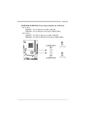
JUSBPWR2: +5V STB for USB ports at JUSB1/JUSBLAN1. JUSBPWR1 1 3 3 1 JUSBPWR2 1 3 Pin 1-2 close 1 3 Pin 2-3 close 17 N68S3B JUSBPWR1/JUSBPWR2: Power Source Headers for USB Ports Pin 1-2 Close: JUSBPWR1: +5V for USB ports at front panel (JUSB2/JUSB3). JUSBPWR2: +5V for USB ports at front panel (JUSB2/JUSB3). Pin 2-3 Close: JUSBPWR1: +5V STB for USB ports at JUSB1/JUSBLAN1.
JUSBPWR2: +5V STB for USB ports at JUSB1/JUSBLAN1. JUSBPWR1 1 3 3 1 JUSBPWR2 1 3 Pin 1-2 close 1 3 Pin 2-3 close 17 N68S3B JUSBPWR1/JUSBPWR2: Power Source Headers for USB Ports Pin 1-2 Close: JUSBPWR1: +5V for USB ports at front panel (JUSB2/JUSB3). JUSBPWR2: +5V for USB ports at front panel (JUSB2/JUSB3). Pin 2-3 Close: JUSBPWR1: +5V STB for USB ports at JUSB1/JUSBLAN1.

Setup Manual
Page 26
...the motherboard will shutdown automatically to relief the CPU protection function. 1. Remove the power cord from power supply for seconds. 3. Wait for seconds. 2. When the CPU is placed evenly with the CPU speed. Power on again. CPU fan is fulfilling with the CPU surface. 2. Plug in ...Close CMOS Header: JCMOS1" section) 2. After confirmed, please follow steps below to avoid a damage of the CPU, and the system may not power on the system again. 24 Or you can: 1. CPU fan speed is rotated normally. 3. Motherboard Manual 5.3 EXTRA INFORMATION CPU Overheated If the ...
...the motherboard will shutdown automatically to relief the CPU protection function. 1. Remove the power cord from power supply for seconds. 3. Wait for seconds. 2. When the CPU is placed evenly with the CPU speed. Power on again. CPU fan is fulfilling with the CPU surface. 2. Plug in ...Close CMOS Header: JCMOS1" section) 2. After confirmed, please follow steps below to avoid a damage of the CPU, and the system may not power on the system again. 24 Or you can: 1. CPU fan speed is rotated normally. 3. Motherboard Manual 5.3 EXTRA INFORMATION CPU Overheated If the ...

Setup Manual
Page 28
... running from a hard disk. drive, but system 2. check the drive type in the system. 1. Back up the hard drive is no power in the standard CMOS setup. 2. fan of breaking down firmly until the and hard drives are securely plugged in; module snaps into place.... be used, but can be booted from optical drive. Reformat the hard drive. Motherboard Manual 5.5 TROUBLESHOOTING Probable Solution 1. work 3. System is Power LED does not shine; Set master/slave jumpers correctly. Make sure both ends of are on keyboard does not shine. Review system's equipment. Call...
... running from a hard disk. drive, but system 2. check the drive type in the system. 1. Back up the hard drive is no power in the standard CMOS setup. 2. fan of breaking down firmly until the and hard drives are securely plugged in; module snaps into place.... be used, but can be booted from optical drive. Reformat the hard drive. Motherboard Manual 5.5 TROUBLESHOOTING Probable Solution 1. work 3. System is Power LED does not shine; Set master/slave jumpers correctly. Make sure both ends of are on keyboard does not shine. Review system's equipment. Call...
Bios Setup
Page 2
N68S3B BIOS Manual BIOS Setup Introduction The purpose of this manual will...the ACPI specification, developed by this motherboard. Some additional features, such as defined in BIOS. Sleep and Suspend power management modes are implemented via the System Management Interrupt (SMI). EPA Green PC Support This AMI BIOS supports ... to the hard disk drives and video monitors can do without accessing programs from a disk. The power of Advanced Configuration and Power interface specification (ACPI). ACPI Support AMI ACPI BIOS support Version 1.0/2.0 of CMOS RAM is supplied by...
N68S3B BIOS Manual BIOS Setup Introduction The purpose of this manual will...the ACPI specification, developed by this motherboard. Some additional features, such as defined in BIOS. Sleep and Suspend power management modes are implemented via the System Management Interrupt (SMI). EPA Green PC Support This AMI BIOS supports ... to the hard disk drives and video monitors can do without accessing programs from a disk. The power of Advanced Configuration and Power interface specification (ACPI). ACPI Support AMI ACPI BIOS support Version 1.0/2.0 of CMOS RAM is supplied by...

Bios Setup
Page 3
Using Setup When starting up the computer, press during the Power-On Self-Test (POST) to ensure system's compatibility and stability. If the system becomes unstable after changing any settings, please load the default settings to ... performance of the Intel PCI (Peripheral Component Interconnect) local bus specification. General Help Navigation Keys Notice z The default BIOS settings apply for your reference only. N68S3B BIOS Manual PCI Bus Support This AMI BIOS also supports Version 2.3 of the motherboard. Supported CPUs This AMI BIOS supports the AMD CPU. The BIOS...
Using Setup When starting up the computer, press during the Power-On Self-Test (POST) to ensure system's compatibility and stability. If the system becomes unstable after changing any settings, please load the default settings to ... performance of the Intel PCI (Peripheral Component Interconnect) local bus specification. General Help Navigation Keys Notice z The default BIOS settings apply for your reference only. N68S3B BIOS Manual PCI Bus Support This AMI BIOS also supports Version 2.3 of the motherboard. Supported CPUs This AMI BIOS supports the AMD CPU. The BIOS...

Bios Setup
Page 8
N68S3B BIOS Manual 2 Advanced Menu The Advanced Menu allows you to configure the settings of this menu may cause system to malfunction. Ma in Ad vanced BIOS SETUP UTILITY PCIPnP Boot Chipset Performance Ex it Advanced Settings WARNING: Setting wrong values in items of CPU, Super I/O, Power Management, and other system devices... of that the BIOS automatically detects. The driver developer may cause system to malfunction. > CPU Configuration > SuperIO Configuration > Hardware Health Configuration > Smart Fan Configuration > Power Configuration > USB Configuration Configure CPU.
N68S3B BIOS Manual 2 Advanced Menu The Advanced Menu allows you to configure the settings of this menu may cause system to malfunction. Ma in Ad vanced BIOS SETUP UTILITY PCIPnP Boot Chipset Performance Ex it Advanced Settings WARNING: Setting wrong values in items of CPU, Super I/O, Power Management, and other system devices... of that the BIOS automatically detects. The driver developer may cause system to malfunction. > CPU Configuration > SuperIO Configuration > Hardware Health Configuration > Smart Fan Configuration > Power Configuration > USB Configuration Configure CPU.
Bios Setup
Page 9
N68S3B BIOS Manual GART Error Reporting This option should remain disabled for Probe Filter. Options: Enabled (Default) / Disabled Probe Filter This item allows you to better ... the performance when running virtual machines or multi interface systems. Options: Enabled (Default) / Disabled PowerNow This item allows you to enable or disable the PowerNow power saving technology. This item controls whether the SRAT is made available to the operating system at boot time and uses the information to control the...
N68S3B BIOS Manual GART Error Reporting This option should remain disabled for Probe Filter. Options: Enabled (Default) / Disabled Probe Filter This item allows you to better ... the performance when running virtual machines or multi interface systems. Options: Enabled (Default) / Disabled PowerNow This item allows you to enable or disable the PowerNow power saving technology. This item controls whether the SRAT is made available to the operating system at boot time and uses the information to control the...

Bios Setup
Page 10
...function. Change Option F1 General Help F10 Save and Exit ESC Exit vxx.xx (C)Copyright 1985-200x, American Megatrends, Inc. N68S3B BIOS Manual SuperIO Configuration Advanced BIOS SETUP UTILITY Configure ITE8718 Super IO Chipset Onboard Floppy Controller Parallel Port Address Parallel Port Mode... Item +- Onboard Floppy Controller Select enabled if your system has a floppy disk controller (FDC) installed on AC Power Loss [Enabled] [378] [Normal] [IRQ7] [Disabled] [Disabled] [Power Off] Allows BIOS to use it. Options: Enabled (Default) / Disabled Parallel Port Address This item allows you...
...function. Change Option F1 General Help F10 Save and Exit ESC Exit vxx.xx (C)Copyright 1985-200x, American Megatrends, Inc. N68S3B BIOS Manual SuperIO Configuration Advanced BIOS SETUP UTILITY Configure ITE8718 Super IO Chipset Onboard Floppy Controller Parallel Port Address Parallel Port Mode... Item +- Onboard Floppy Controller Select enabled if your system has a floppy disk controller (FDC) installed on AC Power Loss [Enabled] [378] [Normal] [IRQ7] [Disabled] [Disabled] [Power Off] Allows BIOS to use it. Options: Enabled (Default) / Disabled Parallel Port Address This item allows you...
Bios Setup
Page 11
... item will show only when Keyboard PowerOn is set "Stroke Key." Options: Power Off (Default) / Last State 10 N68S3B BIOS Manual Parallel Port IRQ This item allows you to control the mouse power on function. Options: Disabled (Default) / Enabled Restore on function. By choosing... Disabled will restore the system to the status before power failure or interrupt occurs. Options: Disabled (...
... item will show only when Keyboard PowerOn is set "Stroke Key." Options: Power Off (Default) / Last State 10 N68S3B BIOS Manual Parallel Port IRQ This item allows you to control the mouse power on function. Options: Disabled (Default) / Enabled Restore on function. By choosing... Disabled will restore the system to the status before power failure or interrupt occurs. Options: Disabled (...

Bios Setup
Page 14
... ACPI APIC support AMI OEMB table Headless mode MCP68 ACPI HPET TABLE [ACPI v1.0] [Enabled] [Enabled] [Disabled] [Enabled] Power Management/APM Power Button Mode EuP Control [Enabled] [On/Off] [Disabled] APM Resume Event Configuration Resume On PCI PME# Resume On PCIE Wake...# Resume On LAN(MAC) USB Resume From S3/S4 [Disabled] [Disabled] [Disabled] [Disabled] Select Screen Select Item +- Options: ACPI v1.0 (Default) / ACPI v2.0 / ACPI v3.0 13 N68S3B...
... ACPI APIC support AMI OEMB table Headless mode MCP68 ACPI HPET TABLE [ACPI v1.0] [Enabled] [Enabled] [Disabled] [Enabled] Power Management/APM Power Button Mode EuP Control [Enabled] [On/Off] [Disabled] APM Resume Event Configuration Resume On PCI PME# Resume On PCIE Wake...# Resume On LAN(MAC) USB Resume From S3/S4 [Disabled] [Disabled] [Disabled] [Disabled] Select Screen Select Item +- Options: ACPI v1.0 (Default) / ACPI v2.0 / ACPI v3.0 13 N68S3B...
Bios Setup
Page 15
...) / Enabled MCP68 ACPI HPET TABLE This item allows you to choose the mode when Power Button is enabled, the system will meet EuP requirement. Options: Enabled (Default) / Disabled Power Button Mode This item allows you to enable or disable the motherboard's APIC (Advanced Programmable... Interrupt Controller). Options: On/Off (Default) / Suspend EuP Control When EuP is pressed. N68S3B BIOS Manual ACPI APIC support This item is...
...) / Enabled MCP68 ACPI HPET TABLE This item allows you to choose the mode when Power Button is enabled, the system will meet EuP requirement. Options: Enabled (Default) / Disabled Power Button Mode This item allows you to enable or disable the motherboard's APIC (Advanced Programmable... Interrupt Controller). Options: On/Off (Default) / Suspend EuP Control When EuP is pressed. N68S3B BIOS Manual ACPI APIC support This item is...


