
Setup Manual
Page 2
Table of Contents Chapter 1: Introduction 1 1.1 Before You Start 1 1.2 Package Checklist 1 1.3 Motherboard Features 2 1.4 Rear Panel Connectors 3 1.5 Motherboard Layout 4 Chapter 2: Hardware Installation 5 2.1 Installing Central Processing Unit (CPU 5 2.2 FAN Headers 7 2.3 Installing System Memory 8 2.4 Connectors and Slots 10 Chapter 3: Headers & Jumpers Setup 13 3.1 How to ...
Table of Contents Chapter 1: Introduction 1 1.1 Before You Start 1 1.2 Package Checklist 1 1.3 Motherboard Features 2 1.4 Rear Panel Connectors 3 1.5 Motherboard Layout 4 Chapter 2: Hardware Installation 5 2.1 Installing Central Processing Unit (CPU 5 2.2 FAN Headers 7 2.3 Installing System Memory 8 2.4 Connectors and Slots 10 Chapter 3: Headers & Jumpers Setup 13 3.1 How to ...

Setup Manual
Page 3
... ) USB 2.0 Cable X1 (optional) Serial ATA Power Cable X 1 (optional) Note: The package contents may be differed by area or your motherboard version. 1 CHAPTER 1: INTRODUCTION N68S3B 1.1 BEFORE YOU START Thank you take the motherboard out from dangerous area, such as heat source, humid air and water. 1.2 PACKAGE CHECKLIST IDE Cable X 1 (optional) Serial ATA Cable...
... ) USB 2.0 Cable X1 (optional) Serial ATA Power Cable X 1 (optional) Note: The package contents may be differed by area or your motherboard version. 1 CHAPTER 1: INTRODUCTION N68S3B 1.1 BEFORE YOU START Thank you take the motherboard out from dangerous area, such as heat source, humid air and water. 1.2 PACKAGE CHECKLIST IDE Cable X 1 (optional) Serial ATA Cable...

Setup Manual
Page 4
Motherboard Manual 1.3 MOTHERBOARD FEATURES SPEC Socket AM3 AMD 64 Architecture enables 32 and 64 bit CPU AMD Phenom II/ Athlon II processors computing (Maximum Watt: 95W) Supports Hyper ...
Motherboard Manual 1.3 MOTHERBOARD FEATURES SPEC Socket AM3 AMD 64 Architecture enables 32 and 64 bit CPU AMD Phenom II/ Athlon II processors computing (Maximum Watt: 95W) Supports Hyper ...

Setup Manual
Page 6
JUSB PWR2 JUSB2 JUSB3 JCMOS1 Super I/O SATA2 SATA1 JSFAN JPANEL1 4 Motherboard Manual 1.5 MOTHERBOARD LAYOUT JKB MS JKB_PWR JATXP WR4 J ATXPW R1 So ck et A M 3 JVGA DDR3_A1 DDR3_B1 IDE J USB1 JCFAN JUSBLA N1 JUSBPWR1 JA UDIO1 BAT1 GeForce 7025/ nForce 630a LAN JAU DIOF Codec JPRNT PEX16_1 BIOS PCI1 Note: ■ represents the 1st pin.
JUSB PWR2 JUSB2 JUSB3 JCMOS1 Super I/O SATA2 SATA1 JSFAN JPANEL1 4 Motherboard Manual 1.5 MOTHERBOARD LAYOUT JKB MS JKB_PWR JATXP WR4 J ATXPW R1 So ck et A M 3 JVGA DDR3_A1 DDR3_B1 IDE J USB1 JCFAN JUSBLA N1 JUSBPWR1 JA UDIO1 BAT1 GeForce 7025/ nForce 630a LAN JAU DIOF Codec JPRNT PEX16_1 BIOS PCI1 Note: ■ represents the 1st pin.

Setup Manual
Page 8
Step 4: Put the CPU Fan on the CPU and buckle it. Connect the CPU FAN power cable to complete the installation. This completes the installation. 6 Motherboard Manual Step 3: Hold the CPU down firmly, and then close the lever toward direct B to the JCFAN.
Step 4: Put the CPU Fan on the CPU and buckle it. Connect the CPU FAN power cable to complete the installation. This completes the installation. 6 Motherboard Manual Step 3: Hold the CPU down firmly, and then close the lever toward direct B to the JCFAN.

Setup Manual
Page 10
Memory Modules 1. Align a DIMM on the slot so that the notch on the DIMM matches the break on the Slot. 2. DDR3 _A1 DDR3 _B1 Motherboard Manual 2.3 INSTALLING SYSTEM MEMORY A. Unlock a DIMM slot by pressing the retaining clips outward. Insert the DIMM vertically and firmly into the slot until the retaining chip snap back in place and the DIMM is properly seated. 8
Memory Modules 1. Align a DIMM on the slot so that the notch on the DIMM matches the break on the Slot. 2. DDR3 _A1 DDR3 _B1 Motherboard Manual 2.3 INSTALLING SYSTEM MEMORY A. Unlock a DIMM slot by pressing the retaining clips outward. Insert the DIMM vertically and firmly into the slot until the retaining chip snap back in place and the DIMM is properly seated. 8

Setup Manual
Page 12
Motherboard Manual 2.4 CONNECTORS AND SLOTS IDE: IDE/ATAPI Connector The motherboard has a 32-bit Enhanced PCI IDE Controller that provides PIO Mode 0~4, Bus Master, and Ultra DMA 33/66/100/133 functionality. The IDE connector can connect a master and a slave drive, so you can connect up to two drives. 40 39 21 JATXPWR4: ATX Power Source Connector This connect provides +12V to CPU power circuit. 4 3 1 2 Pin Assignment 1 +12V 2 +12V 3 Ground 4 Ground 10
Motherboard Manual 2.4 CONNECTORS AND SLOTS IDE: IDE/ATAPI Connector The motherboard has a 32-bit Enhanced PCI IDE Controller that provides PIO Mode 0~4, Bus Master, and Ultra DMA 33/66/100/133 functionality. The IDE connector can connect a master and a slave drive, so you can connect up to two drives. 40 39 21 JATXPWR4: ATX Power Source Connector This connect provides +12V to CPU power circuit. 4 3 1 2 Pin Assignment 1 +12V 2 +12V 3 Ground 4 Ground 10
Setup Manual
Page 14
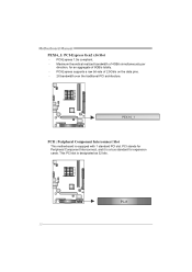
PCI-Express 1.0a compliant. - PCI-Express supports a raw bit-rate of 4GB/s simultaneously per direction, for Peripheral Component Interconnect, and it is equipped with 1 standard PCI slot. PEX16_1 PCI1: Peripheral Component Interconnect Slot This motherboard is a bus standard for expansion cards. PCI stands for an aggregate of 8GB/s totally. - This PCI slot is designated as 32 bits. PCI1 12 Maximum theoretical realized bandwidth of 2.5Gb/s on the data pins. - 2X bandwidth over the traditional PCI architecture. Motherboard Manual PEX16_1: PCI-Express Gen2 x16 Slot -
PCI-Express 1.0a compliant. - PCI-Express supports a raw bit-rate of 4GB/s simultaneously per direction, for Peripheral Component Interconnect, and it is equipped with 1 standard PCI slot. PEX16_1 PCI1: Peripheral Component Interconnect Slot This motherboard is a bus standard for expansion cards. PCI stands for an aggregate of 8GB/s totally. - This PCI slot is designated as 32 bits. PCI1 12 Maximum theoretical realized bandwidth of 2.5Gb/s on the data pins. - 2X bandwidth over the traditional PCI architecture. Motherboard Manual PEX16_1: PCI-Express Gen2 x16 Slot -

Setup Manual
Page 16
... 14 JUSB2 JUSB3 10 9 2 1 Pin Assignment 1 +5V (fused) 2 +5V (fused) 3 USB4 USB5 USB+ 6 USB+ 7 Ground 8 Ground 9 NC 10 Key SATA1/SATA2: Serial ATA Connectors The motherboard has a PCI to connect additional USB cable on the PC front panel, and also can be connected with transfer rate of 3.0Gb.../s. Motherboard Manual JUSB2/JUSB3: Headers for USB 2.0 Ports at Front Panel These headers allow user to SATA Controller with 2 channels SATA interface, it satisfies the SATA 2.0...
... 14 JUSB2 JUSB3 10 9 2 1 Pin Assignment 1 +5V (fused) 2 +5V (fused) 3 USB4 USB5 USB+ 6 USB+ 7 Ground 8 Ground 9 NC 10 Key SATA1/SATA2: Serial ATA Connectors The motherboard has a PCI to connect additional USB cable on the PC front panel, and also can be connected with transfer rate of 3.0Gb.../s. Motherboard Manual JUSB2/JUSB3: Headers for USB 2.0 Ports at Front Panel These headers allow user to SATA Controller with 2 channels SATA interface, it satisfies the SATA 2.0...

Setup Manual
Page 17
...panel. This header allows only HD audio front panel connector; Reset your desired password or clear the CMOS data. 15 Remove AC power line. 2. N68S3B JAUDIOF: Front Panel Audio Header This header allows user to "Pin 2-3 close ". 5. Wait for five seconds. 4. Pin Assignment 1 Mic Left... line in 2 1 0 10 Jack Sense 1 9 JCMOS1: Clear CMOS Header By placing the jumper on the AC. 6. Set the jumper to avoid damaging the motherboard. 31 Pin 1-2 Close: Normal Operation (default). 31 3 1 Pin 2-3 Close: Clear CMOS data. ※ Clear CMOS Procedures: 1. Power on pin2-3, it ...
...panel. This header allows only HD audio front panel connector; Reset your desired password or clear the CMOS data. 15 Remove AC power line. 2. N68S3B JAUDIOF: Front Panel Audio Header This header allows user to "Pin 2-3 close ". 5. Wait for five seconds. 4. Pin Assignment 1 Mic Left... line in 2 1 0 10 Jack Sense 1 9 JCMOS1: Clear CMOS Header By placing the jumper on the AC. 6. Set the jumper to avoid damaging the motherboard. 31 Pin 1-2 Close: Normal Operation (default). 31 3 1 Pin 2-3 Close: Clear CMOS data. ※ Clear CMOS Procedures: 1. Power on pin2-3, it ...

Setup Manual
Page 18
Motherboard Manual JPRNT: Printer Port Connector This header allows you to connect printer port on the PC. 2 26 1 25 Pin Assignment 1 -Strobe 2 -ALF 3 Data 0 4 -Error 5 Data 1 6 -Init 7 Data 2 8 -Scltin 9 Data 3 10 Ground 11 Data 4 12 Ground 13 Data 5 Pin Assignment 14 Ground 15 Data 6 16 Ground 17 Data 7 18 Ground 19 -ACK 20 Ground 21 Busy 22 Ground 23 PE 24 Ground 25 SCLT 26 Key JKB_PWR: Power Source Header for PS/2 Keyboard and Mouse 1 3 1 3 Pin 1-2 close +5V for PS/2 keyboard and mouse. 1 3 Pin 2-3 close +5V STB for PS/2 keyboard and mouse. 16
Motherboard Manual JPRNT: Printer Port Connector This header allows you to connect printer port on the PC. 2 26 1 25 Pin Assignment 1 -Strobe 2 -ALF 3 Data 0 4 -Error 5 Data 1 6 -Init 7 Data 2 8 -Scltin 9 Data 3 10 Ground 11 Data 4 12 Ground 13 Data 5 Pin Assignment 14 Ground 15 Data 6 16 Ground 17 Data 7 18 Ground 19 -ACK 20 Ground 21 Busy 22 Ground 23 PE 24 Ground 25 SCLT 26 Key JKB_PWR: Power Source Header for PS/2 Keyboard and Mouse 1 3 1 3 Pin 1-2 close +5V for PS/2 keyboard and mouse. 1 3 Pin 2-3 close +5V STB for PS/2 keyboard and mouse. 16

Setup Manual
Page 20
... on the system environment. No capacity loss penalty for large files. Features and Benefits Drives: Minimum 2, and maximum is lost. Fault Tolerance: No. Motherboard Manual CHAPTER 4: RAID FUNCTIONS 4.1 OPERATING SYSTEM Supports Windows XP, Windows Vista, and Windows 7. 4.2 RAID ARRAYS RAID supports the following types of the RAID set based...
... on the system environment. No capacity loss penalty for large files. Features and Benefits Drives: Minimum 2, and maximum is lost. Fault Tolerance: No. Motherboard Manual CHAPTER 4: RAID FUNCTIONS 4.1 OPERATING SYSTEM Supports Windows XP, Windows Vista, and Windows 7. 4.2 RAID ARRAYS RAID supports the following types of the RAID set based...

Setup Manual
Page 22
... will list the compatible driver for available manual. You will auto detect your motherboard and operating system. Click on the Manual icon to browse for your motherboard and operating system. Click on each software title to launch the installation program. Motherboard Manual CHAPTER 5: USEFUL HELP 5.1 DRIVER INSTALLATION NOTE After you insert the Driver...
... will list the compatible driver for available manual. You will auto detect your motherboard and operating system. Click on the Manual icon to browse for your motherboard and operating system. Click on each software title to launch the installation program. Motherboard Manual CHAPTER 5: USEFUL HELP 5.1 DRIVER INSTALLATION NOTE After you insert the Driver...
Setup Manual
Page 24
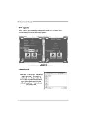
Choose the position to update your motherboard BIOS under Windows system. Motherboard Manual BIOS Update BIOS Update is a convenient utility which allows you to save file and enter file name. (We recommend that the file name should be English/number and no longer than 7 characters.) Then click Save. 22 AWARD BIOS Show current BIOS information AMI BIOS Clear CMOS function (Only for AWARD BIOS) Save current BIOS to a .bin file Update BIOS with a BIOS file Once click on this button, the saving dialog will show.
Choose the position to update your motherboard BIOS under Windows system. Motherboard Manual BIOS Update BIOS Update is a convenient utility which allows you to save file and enter file name. (We recommend that the file name should be English/number and no longer than 7 characters.) Then click Save. 22 AWARD BIOS Show current BIOS information AMI BIOS Clear CMOS function (Only for AWARD BIOS) Save current BIOS to a .bin file Update BIOS with a BIOS file Once click on this button, the saving dialog will show.

Setup Manual
Page 26
...See "Close CMOS Header: JCMOS1" section) 2. Plug in the power cord and boot up the system. CPU fan is over heated, the motherboard will shutdown automatically to relief the CPU protection function. 1. CPU fan speed is placed evenly with the CPU speed. In this case, please... double check: 1. The CPU cooler surface is fulfilling with the CPU surface. 2. Motherboard Manual 5.3 EXTRA INFORMATION CPU Overheated If the system shutdown automatically after power on system for seconds. 3. Wait for seconds, that means the ...
...See "Close CMOS Header: JCMOS1" section) 2. Plug in the power cord and boot up the system. CPU fan is over heated, the motherboard will shutdown automatically to relief the CPU protection function. 1. CPU fan speed is placed evenly with the CPU speed. In this case, please... double check: 1. The CPU cooler surface is fulfilling with the CPU surface. 2. Motherboard Manual 5.3 EXTRA INFORMATION CPU Overheated If the system shutdown automatically after power on system for seconds. 3. Wait for seconds, that means the ...
Setup Manual
Page 27
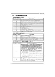
... happens again. Consult your system manufacturer's technical support. Fatal error indicating a serious problem with known good modules. Before declaring the motherboard beyond all expansion cards except the video adapter. If the system video adapter is an integrated part of the system board, the...board may be faulty. 25 Remove all hope, eliminate the possibility of interference by a malfunctioning add-in card. 5.4 AMI BIOS BEEP CODE N68S3B Boot Block Beep Codes Number of Beeps Description 1 No media present. (Insert diskette in floppy drive A:) 2 "AMIBOOT.ROM" file not...
... happens again. Consult your system manufacturer's technical support. Fatal error indicating a serious problem with known good modules. Before declaring the motherboard beyond all expansion cards except the video adapter. If the system video adapter is an integrated part of the system board, the...board may be faulty. 25 Remove all hope, eliminate the possibility of interference by a malfunctioning add-in card. 5.4 AMI BIOS BEEP CODE N68S3B Boot Block Beep Codes Number of Beeps Description 1 No media present. (Insert diskette in floppy drive A:) 2 "AMIBOOT.ROM" file not...

Setup Manual
Page 28
... and select correct drive types. Replace cable. All hard disks are securely plugged in the system. 1. System is in setup. Set master/slave jumpers correctly. Motherboard Manual 5.5 TROUBLESHOOTING Probable Solution 1. Make sure power cable is no power in ; module snaps into place. There is Power LED does not shine;
... and select correct drive types. Replace cable. All hard disks are securely plugged in the system. 1. System is in setup. Set master/slave jumpers correctly. Motherboard Manual 5.5 TROUBLESHOOTING Probable Solution 1. Make sure power cable is no power in ; module snaps into place. There is Power LED does not shine;
Bios Setup
Page 2
...the booting process, loading and executing the operating system. Sleep and Suspend power management modes are implemented via the System Management Interrupt (SMI). N68S3B BIOS Manual BIOS Setup Introduction The purpose of this manual will to guide you through the options and settings in BIOS Setup. The rest ... determines what a computer can also be managed by a battery so that it retains the Setup information when the power is supplied by this motherboard. The power of the input and output devices such as defined in BIOS. Plug and Play Support This AMI BIOS supports the Plug and ...
...the booting process, loading and executing the operating system. Sleep and Suspend power management modes are implemented via the System Management Interrupt (SMI). N68S3B BIOS Manual BIOS Setup Introduction The purpose of this manual will to guide you through the options and settings in BIOS Setup. The rest ... determines what a computer can also be managed by a battery so that it retains the Setup information when the power is supplied by this motherboard. The power of the input and output devices such as defined in BIOS. Plug and Play Support This AMI BIOS supports the Plug and ...

Bios Setup
Page 3
...bus specification. Supported CPUs This AMI BIOS supports the AMD CPU. Use Load Setup Default under the Exit Menu. z The content of the motherboard. If the system becomes unstable after changing any mistakes found in this manual is for that particular menu are at the top right corner, and... this user's manual and any system damage that may be responsible for most conditions to be caused by wrong-settings. 2 N68S3B BIOS Manual PCI Bus Support This AMI BIOS also supports Version 2.3 of the selected item. Navigation Keys for your reference only. z For better ...
...bus specification. Supported CPUs This AMI BIOS supports the AMD CPU. Use Load Setup Default under the Exit Menu. z The content of the motherboard. If the system becomes unstable after changing any mistakes found in this manual is for that particular menu are at the top right corner, and... this user's manual and any system damage that may be responsible for most conditions to be caused by wrong-settings. 2 N68S3B BIOS Manual PCI Bus Support This AMI BIOS also supports Version 2.3 of the selected item. Navigation Keys for your reference only. z For better ...
Bios Setup
Page 15
... a server-specific feature. Options: Enabled (Default) / Disabled Power Button Mode This item allows you to enable or disable the motherboard's APIC (Advanced Programmable Interrupt Controller). Windows Server 2003) must support headless operation. N68S3B BIOS Manual ACPI APIC support This item is used to choose the mode when Power Button is pressed. Options...
... a server-specific feature. Options: Enabled (Default) / Disabled Power Button Mode This item allows you to enable or disable the motherboard's APIC (Advanced Programmable Interrupt Controller). Windows Server 2003) must support headless operation. N68S3B BIOS Manual ACPI APIC support This item is used to choose the mode when Power Button is pressed. Options...


