
Setup Manual
Page 1
P4M900-M7 SE/P4M890-M7 TE Setup Manual FCC Information and Copyright This equipment has been tested and found in this publication, in part or in whole, is not allowed without ...
P4M900-M7 SE/P4M890-M7 TE Setup Manual FCC Information and Copyright This equipment has been tested and found in this publication, in part or in whole, is not allowed without ...

Setup Manual
Page 3
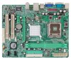
P4M900-M7 SE/P4M890-M7 TE CHAPTER 1: INTRODUCTION 1.1 BEFORE YOU START Thank you take the motherboard out from dangerous area, such as heat source, humid air and water. 1.2 PACKAGE CHECKLIST HDD ...
P4M900-M7 SE/P4M890-M7 TE CHAPTER 1: INTRODUCTION 1.1 BEFORE YOU START Thank you take the motherboard out from dangerous area, such as heat source, humid air and water. 1.2 PACKAGE CHECKLIST HDD ...
Setup Manual
Page 4
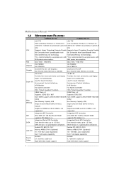
...out High-Definition Audio support ALC662 5.1 channels audio out High-Definition Audio support 4 SATA Version 1.0 specification compliant. Motherboard Manual 1.3 MOTHERBOARD FEATURES CPU FSB P4M900-M7 SE P4M890-M7 TE LGA 775 LGA 775 Intel Core2Duo/ Pentium 4 / Pentium D / Intel Core2Duo/ Pentium 4 / Pentium D / Celeron D / Celeron 4xx processor up to... 95W power consumption. 533 / 800 / 1066 MHz 533 / 800 / 1066 MHz Chipset VIA P4M900 VIA VT8237A VIA P4M890 VIA VT8237A Graphic Chrome9 HC 3D / 2D Graphics Max Shared Video Memory is 256 MB Unichrome Pro IGP Max Shared Video...
...out High-Definition Audio support ALC662 5.1 channels audio out High-Definition Audio support 4 SATA Version 1.0 specification compliant. Motherboard Manual 1.3 MOTHERBOARD FEATURES CPU FSB P4M900-M7 SE P4M890-M7 TE LGA 775 LGA 775 Intel Core2Duo/ Pentium 4 / Pentium D / Intel Core2Duo/ Pentium 4 / Pentium D / Celeron D / Celeron 4xx processor up to... 95W power consumption. 533 / 800 / 1066 MHz 533 / 800 / 1066 MHz Chipset VIA P4M900 VIA VT8237A VIA P4M890 VIA VT8237A Graphic Chrome9 HC 3D / 2D Graphics Max Shared Video Memory is 256 MB Unichrome Pro IGP Max Shared Video...

Setup Manual
Page 5
...The input / output function of each audio jack listed above represents the default setting. P4M900-M7 SE/P4M890-M7 TE Slots P4M900-M7 SE PCI Express x 16 slot x1 PCI Express x 1 slot x1 PCI slot x2 P4M890-M7 TE PCI Express x 16 slot x1 PCI Express x 1 slot x1 PCI slot x2 Floppy connector...190 mm (W) x 244 mm (L) Special Feature RAID 0 / 1 support RAID 0 / 1 support OS Support Windows 2000 / XP / VISTA Windows 2000 / XP Biostar Reserves the right to add or remove Biostar Reserves the right to the audio port, please use the Line In (blue) and Mic In (Pink) audio jack. 5
...The input / output function of each audio jack listed above represents the default setting. P4M900-M7 SE/P4M890-M7 TE Slots P4M900-M7 SE PCI Express x 16 slot x1 PCI Express x 1 slot x1 PCI slot x2 P4M890-M7 TE PCI Express x 16 slot x1 PCI Express x 1 slot x1 PCI slot x2 Floppy connector...190 mm (W) x 244 mm (L) Special Feature RAID 0 / 1 support RAID 0 / 1 support OS Support Windows 2000 / XP / VISTA Windows 2000 / XP Biostar Reserves the right to add or remove Biostar Reserves the right to the audio port, please use the Line In (blue) and Mic In (Pink) audio jack. 5

Setup Manual
Page 7
P4M900-M7 SE/P4M890-M7 TE CHAPTER 2: HARDWARE INSTALLATION 2.1 INSTALLING CENTRAL PROCESSING UNIT (CPU) Special Notice: Remove Pin Cap before installation, and make good preservation for future use. Pin Cap Step 1: Pull the socket locking lever out from the socket and then raise the lever up to ensure pin legs won't be damaged. When the CPU is removed, cover the Pin Cap on the empty socket to a 90-degree angle. 7
P4M900-M7 SE/P4M890-M7 TE CHAPTER 2: HARDWARE INSTALLATION 2.1 INSTALLING CENTRAL PROCESSING UNIT (CPU) Special Notice: Remove Pin Cap before installation, and make good preservation for future use. Pin Cap Step 1: Pull the socket locking lever out from the socket and then raise the lever up to ensure pin legs won't be damaged. When the CPU is removed, cover the Pin Cap on the empty socket to a 90-degree angle. 7

Setup Manual
Page 9
... Fan Header Pin Assignment 1 Ground 2 +12V 3 FAN RPM rate sense 3 1 Note: The JSFAN1 supports 3-pin head connector and the JCFAN1 supports 4-pin head connector. P4M900-M7 SE/P4M890-M7 TE 2.2 FAN HEADERS These fan headers support cooling-fans built in the computer. When connecting with wires onto connectors, please note that the red wire is...
... Fan Header Pin Assignment 1 Ground 2 +12V 3 FAN RPM rate sense 3 1 Note: The JSFAN1 supports 3-pin head connector and the JCFAN1 supports 4-pin head connector. P4M900-M7 SE/P4M890-M7 TE 2.2 FAN HEADERS These fan headers support cooling-fans built in the computer. When connecting with wires onto connectors, please note that the red wire is...

Setup Manual
Page 11
... floppy disk types. The IDE connectors can connect a master and a slave drive, so you can connect up to IDE1. 40 39 2 1 IDE1 IDE2 11 P4M900-M7 SE/P4M890-M7 TE 2.4 CONNECTORS AND SLOTS FDD1: Floppy Disk Connector The motherboard provides a standard floppy disk connector that provides PIO Mode 0~4, Bus Master, and Ultra DMA 33/66...
... floppy disk types. The IDE connectors can connect a master and a slave drive, so you can connect up to IDE1. 40 39 2 1 IDE1 IDE2 11 P4M900-M7 SE/P4M890-M7 TE 2.4 CONNECTORS AND SLOTS FDD1: Floppy Disk Connector The motherboard provides a standard floppy disk connector that provides PIO Mode 0~4, Bus Master, and Ultra DMA 33/66...

Setup Manual
Page 13
P4M900-M7 SE/P4M890-M7 TE CHAPTER 3: HEADERS & JUMPERS SETUP 3.1 HOW TO SETUP JUMPERS The illustration shows how to connect the PC case's front panel switch functions. PWR_LED SLP On/Off ++ - 9 ...
P4M900-M7 SE/P4M890-M7 TE CHAPTER 3: HEADERS & JUMPERS SETUP 3.1 HOW TO SETUP JUMPERS The illustration shows how to connect the PC case's front panel switch functions. PWR_LED SLP On/Off ++ - 9 ...

Setup Manual
Page 15
It will disable the output on the PC front panel, and also can be connected with internal USB devices, like USB card reader. P4M900-M7 SE/P4M890-M7 TE JUSB2/JUSB3: Headers for USB 2.0 Ports at Front Panel This header allows user to connect additional USB cable on back panel audio connectors. 2 10 1 9 Pin ...
It will disable the output on the PC front panel, and also can be connected with internal USB devices, like USB card reader. P4M900-M7 SE/P4M890-M7 TE JUSB2/JUSB3: Headers for USB 2.0 Ports at Front Panel This header allows user to connect additional USB cable on back panel audio connectors. 2 10 1 9 Pin ...

Setup Manual
Page 17
P4M900-M7 SE/P4M890-M7 TE JPRNT1: Printer Port Connector This header allows you to connector printer on the PC. 25 2 1 Pin Assignment 1 -Strobe 2 -ALF 3 Data 0 4 -Error 5 Data 1 6 -Init 7 Data 2 8 -Scltin 9 Data 3 10 Ground 11 Data 4 12 Ground 13 Data 5 Pin Assignment 14 Ground 15 Data 6 16 Ground 17 Data 7 18 Ground 19 -ACK 20 Ground 21 Busy 22 Ground 23 PE 24 Ground 25 SCLT 26 Key 17
P4M900-M7 SE/P4M890-M7 TE JPRNT1: Printer Port Connector This header allows you to connector printer on the PC. 25 2 1 Pin Assignment 1 -Strobe 2 -ALF 3 Data 0 4 -Error 5 Data 1 6 -Init 7 Data 2 8 -Scltin 9 Data 3 10 Ground 11 Data 4 12 Ground 13 Data 5 Pin Assignment 14 Ground 15 Data 6 16 Ground 17 Data 7 18 Ground 19 -ACK 20 Ground 21 Busy 22 Ground 23 PE 24 Ground 25 SCLT 26 Key 17

Setup Manual
Page 19
P4M900-M7 SE/P4M890-M7 TE RAID 1: Every read and write is impaired during drive rebuilds. Fault Tolerance: Yes. RAID techniques can be applied for the storage space of the ...
P4M900-M7 SE/P4M890-M7 TE RAID 1: Every read and write is impaired during drive rebuilds. Fault Tolerance: Yes. RAID techniques can be applied for the storage space of the ...

Setup Manual
Page 21
... on system for seconds. 3. After confirmed, please follow steps below to avoid a damage of the CPU, and the system may not power on again. P4M900-M7 SE/P4M890-M7 TE 5.2 AWARD BIOS BEEP CODE Beep Sound Meaning One long beep followed by two short Video card not found during POST Long beeps every other second...
... on system for seconds. 3. After confirmed, please follow steps below to avoid a damage of the CPU, and the system may not power on again. P4M900-M7 SE/P4M890-M7 TE 5.2 AWARD BIOS BEEP CODE Beep Sound Meaning One long beep followed by two short Video card not found during POST Long beeps every other second...

Setup Manual
Page 23
..., on our main panel. The cool Hardware Monitor smartly indicates the temperatures, voltage and CPU fan speed as well as the chipset information. P4M900-M7 SE/P4M890-M7 TE CHAPTER 6: WARPSPEEDER™ III 6.1 INTRODUCTION [WarpSpeeder™ III], a new powerful control utility, features three user-friendly functions including Overclock Manager, ..., the frequency status of CPU, memory, VGA and PCI along with just one . 6.2 SYSTEM REQUIREMENT OS Support: Windows 98 SE, Windows Me, Windows 2000, Windows XP DirectX: DirectX 8.1 or above. (The Windows XP operating system includes DirectX 8.1.
..., on our main panel. The cool Hardware Monitor smartly indicates the temperatures, voltage and CPU fan speed as well as the chipset information. P4M900-M7 SE/P4M890-M7 TE CHAPTER 6: WARPSPEEDER™ III 6.1 INTRODUCTION [WarpSpeeder™ III], a new powerful control utility, features three user-friendly functions including Overclock Manager, ..., the frequency status of CPU, memory, VGA and PCI along with just one . 6.2 SYSTEM REQUIREMENT OS Support: Windows 98 SE, Windows Me, Windows 2000, Windows XP DirectX: DirectX 8.1 or above. (The Windows XP operating system includes DirectX 8.1.

Setup Manual
Page 25
6.4 WARPSPEEDER™ III P4M900-M7 SE/P4M890-M7 TE 1. Now you double-click the desktop icon, [WarpSpeeder™ III] will be launched. Please refer to the following figure; The On/Off button is Main ...
6.4 WARPSPEEDER™ III P4M900-M7 SE/P4M890-M7 TE 1. Now you double-click the desktop icon, [WarpSpeeder™ III] will be launched. Please refer to the following figure; The On/Off button is Main ...

Setup Manual
Page 27
... may become unstable, click on "OK" to do real-time overclock adjustment. "V3 Engine"/"V6 Engine"/"V9 Engine": Provide user the ability to proceed. P4M900-M7 SE/P4M890-M7 TE Overclock Panel contains these features: a. b. After reboot, the [WarpSpeeder™ III] utility will do fail-safe reboot by click the Verify button.
... may become unstable, click on "OK" to do real-time overclock adjustment. "V3 Engine"/"V6 Engine"/"V9 Engine": Provide user the ability to proceed. P4M900-M7 SE/P4M890-M7 TE Overclock Panel contains these features: a. b. After reboot, the [WarpSpeeder™ III] utility will do fail-safe reboot by click the Verify button.

Setup Manual
Page 29
P4M900-M7 SE/P4M890-M7 TE 5. In this panel, you can get the the version number of all the chipset that are controlled by several separate chipset, [WarpSpeeder™ III] divide ...
P4M900-M7 SE/P4M890-M7 TE 5. In this panel, you can get the the version number of all the chipset that are controlled by several separate chipset, [WarpSpeeder™ III] divide ...

Setup Manual
Page 46
FSB 533 / 800 / 1066 MHz 533 / 800 / 1066 MHz VIA P4M900 ト VIA VT8237A VIA P4M890 VIA VT8237A Chrome9 HC 3D / 2D Graphics クス 256MBです Unichrome Pro IGP 64MBです ...100 / 133 ド ド PIO Mode 0~4 PIO Mode 0~4 ATA ATA 最高1.5 Gb 最高1.5 Gb SATA 1.0 SATA 1.0 46 Motherboard Manual JAPANESE P4M900-M7 SE P4M890-M7 TE CPU LGA 775 LGA 775 Intel Core2Duo/ Pentium 4 / Pentium D / Intel Core2Duo/ Pentium 4 / Pentium D / Celeron D / Celeron 4xx processor up to 3.8 ...
FSB 533 / 800 / 1066 MHz 533 / 800 / 1066 MHz VIA P4M900 ト VIA VT8237A VIA P4M890 VIA VT8237A Chrome9 HC 3D / 2D Graphics クス 256MBです Unichrome Pro IGP 64MBです ...100 / 133 ド ド PIO Mode 0~4 PIO Mode 0~4 ATA ATA 最高1.5 Gb 最高1.5 Gb SATA 1.0 SATA 1.0 46 Motherboard Manual JAPANESE P4M900-M7 SE P4M890-M7 TE CPU LGA 775 LGA 775 Intel Core2Duo/ Pentium 4 / Pentium D / Intel Core2Duo/ Pentium 4 / Pentium D / Celeron D / Celeron 4xx processor up to 3.8 ...

Bios Setup
Page 1
P4M900-M7 SE/P4M890-M7 TE BIOS Setup BIOS Setup 1 1 Main Menu 3 2 Standard CMOS Features 6 3 Advanced BIOS Features 8 4 Advanced Chipset Features 16 5 Integrated Peripherals 20 6 Power Management Setup 26 7 PnP/PCI Configurations 31 8 PC Health Status 34 9 Performance Booster Zone 36 i
P4M900-M7 SE/P4M890-M7 TE BIOS Setup BIOS Setup 1 1 Main Menu 3 2 Standard CMOS Features 6 3 Advanced BIOS Features 8 4 Advanced Chipset Features 16 5 Integrated Peripherals 20 6 Power Management Setup 26 7 PnP/PCI Configurations 31 8 PC Health Status 34 9 Performance Booster Zone 36 i

Bios Setup
Page 2
... Toshiba. 1 Plug and Play Support This PHOENIX-AWARD BIOS supports the Plug and Play Version 1.0A specification and ESCD (Extended System Configuration Data) write. P4M900-M7 SE/P4M890-M7 TE BIOS Setup Introduction The purpose of this manual is turned off. BIOS activates at the first stage of Advanced Configuration and Power interface specification (ACPI...
... Toshiba. 1 Plug and Play Support This PHOENIX-AWARD BIOS supports the Plug and Play Version 1.0A specification and ESCD (Extended System Configuration Data) write. P4M900-M7 SE/P4M890-M7 TE BIOS Setup Introduction The purpose of this manual is turned off. BIOS activates at the first stage of Advanced Configuration and Power interface specification (ACPI...

Bios Setup
Page 3
... (menu bar) Move to navigate in most of the Intel PCI (Peripheral Component Interconnect) local bus specification. Exit Current page and return to quit. P4M900-M7 SE/P4M890-M7 TE PCI Bus Support This PHOENIX-AWARD BIOS also supports Version 3.0 of the place, press to select, use the and keys to change entries, press for...
... (menu bar) Move to navigate in most of the Intel PCI (Peripheral Component Interconnect) local bus specification. Exit Current page and return to quit. P4M900-M7 SE/P4M890-M7 TE PCI Bus Support This PHOENIX-AWARD BIOS also supports Version 3.0 of the place, press to select, use the and keys to change entries, press for...


