
Setup Manual
Page 2
Table of Contents Chapter 1: Introduction 3 1.1 Before You Start 3 1.2 Package Checklist 3 1.3 Motherboard Features 4 1.4 Rear Panel Connectors 6 1.5 Motherboard Layout 7 Chapter 2: Hardware Installation 8 2.1 Installing Central Processing Unit (CPU 8 2.2 FAN Headers 10 2.3 Installing System Memory 11 2.4 Connectors and Slots 13 Chapter 3: Headers & Jumpers Setup 15 3.1 How to Setup Jumpers 15 3.2 Detail Settings 15 Chapter 4: ...
Table of Contents Chapter 1: Introduction 3 1.1 Before You Start 3 1.2 Package Checklist 3 1.3 Motherboard Features 4 1.4 Rear Panel Connectors 6 1.5 Motherboard Layout 7 Chapter 2: Hardware Installation 8 2.1 Installing Central Processing Unit (CPU 8 2.2 FAN Headers 10 2.3 Installing System Memory 11 2.4 Connectors and Slots 13 Chapter 3: Headers & Jumpers Setup 15 3.1 How to Setup Jumpers 15 3.2 Detail Settings 15 Chapter 4: ...

Setup Manual
Page 4
... PIO Mode 0~4, SATA II Integrated Serial ATA Controller Data transfer rates up to 3 Gb/s. Motherboard Manual 1.3 MOTHERBOARD FEATURES SPEC Socket AM2 AMD 64 Architecture enables 32 and 64 bit computing CPU AMD Athlon 64 / Athlon 64 FX / Athlon 64 Supports Hyper Transport and Cool=n=Quiet x2 / Sempron processors FSB Supports up to...
... PIO Mode 0~4, SATA II Integrated Serial ATA Controller Data transfer rates up to 3 Gb/s. Motherboard Manual 1.3 MOTHERBOARD FEATURES SPEC Socket AM2 AMD 64 Architecture enables 32 and 64 bit computing CPU AMD Athlon 64 / Athlon 64 FX / Athlon 64 Supports Hyper Transport and Cool=n=Quiet x2 / Sempron processors FSB Supports up to...

Setup Manual
Page 5
... Size 244 mm(W) x 244 mm(L) Special Features RAID 0 / 1 / 1+0 support OS Support Windows XP / VISTA TA690G AM2 SPEC x1 Each connector supports 2 IDE device x4 Each connector supports 1 SATA devices x1 Support front panel facilities x1 Support ... Support CD audio-in function x1 Support digital audio out function x1 Support digital audio in function x1 CPU Fan power supply (with Smart Fan function) x3 System Fan Power supply x1 Restore CMOS data to...-In/Out and microphone connection Micro ATX Size Board Biostar Reserves the right to add or remove support for any OS With or without notice. 5
... Size 244 mm(W) x 244 mm(L) Special Features RAID 0 / 1 / 1+0 support OS Support Windows XP / VISTA TA690G AM2 SPEC x1 Each connector supports 2 IDE device x4 Each connector supports 1 SATA devices x1 Support front panel facilities x1 Support ... Support CD audio-in function x1 Support digital audio out function x1 Support digital audio in function x1 CPU Fan power supply (with Smart Fan function) x3 System Fan Power supply x1 Restore CMOS data to...-In/Out and microphone connection Micro ATX Size Board Biostar Reserves the right to add or remove support for any OS With or without notice. 5

Setup Manual
Page 8
The CPU will fit only in the correct orientation. 8 Step 2: Pull the lever toward direction A from the socket and then raise the lever up to a 90-degree angle. Step 3: Look for the white triangle on socket, and the gold triangle on CPU should point towards this white triangle. Motherboard Manual CHAPTER 2: HARDWARE INSTALLATION 2.1 INSTALLING CENTRAL PROCESSING UNIT (CPU) Step 1: Remove the socket protection cap.
The CPU will fit only in the correct orientation. 8 Step 2: Pull the lever toward direction A from the socket and then raise the lever up to a 90-degree angle. Step 3: Look for the white triangle on socket, and the gold triangle on CPU should point towards this white triangle. Motherboard Manual CHAPTER 2: HARDWARE INSTALLATION 2.1 INSTALLING CENTRAL PROCESSING UNIT (CPU) Step 1: Remove the socket protection cap.

Setup Manual
Page 9
This completes the installation. 9 Step 5: Put the CPU Fan on the CPU and buckle it. TA690G AM2 Step 4: Hold the CPU down firmly, and then close the lever toward direct B to the JCFAN1. Connect the CPU FAN power cable to complete the installation.
This completes the installation. 9 Step 5: Put the CPU Fan on the CPU and buckle it. TA690G AM2 Step 4: Hold the CPU down firmly, and then close the lever toward direct B to the JCFAN1. Connect the CPU FAN power cable to complete the installation.

Setup Manual
Page 10
... is the positive and should be connected to pin#2, and the black wire is Ground and should be different according to the fan manufacturer. JCFAN1: CPU Fan Header 14 Pin Assignment 1 Ground 2 +12V 3 FAN RPM rate sense 4 Smart Fan Control (By Fan) JNFAN1: North Bridge Fan Header JSFAN1/JSFAN2: System Fan...
... is the positive and should be connected to pin#2, and the black wire is Ground and should be different according to the fan manufacturer. JCFAN1: CPU Fan Header 14 Pin Assignment 1 Ground 2 +12V 3 FAN RPM rate sense 4 Smart Fan Control (By Fan) JNFAN1: North Bridge Fan Header JSFAN1/JSFAN2: System Fan...

Setup Manual
Page 16
... 8 PW _OK 9 Standby Voltage+5V 10 +12V 11 +12V 12 +3.3V JATXPWR2: ATX Power Source Connector By connecting this connector, it will provide +12V to CPU power circuit. 1 4 2 3 Pin Assignment 1 +12V 2 +12V 3 Ground 4 Ground 16
... 8 PW _OK 9 Standby Voltage+5V 10 +12V 11 +12V 12 +3.3V JATXPWR2: ATX Power Source Connector By connecting this connector, it will provide +12V to CPU power circuit. 1 4 2 3 Pin Assignment 1 +12V 2 +12V 3 Ground 4 Ground 16

Setup Manual
Page 21
RSTSW1: This is an on-board Power Switch button. On-Board LED Indicators There are 2 on diagnostics. On-Board Buttons There are 2 LED indicators on -board Reset button. LED_D1 LED_D2 LED_D1 and LED_D2: These 2 LED indicate system power on -board buttons. Please refer to show system status. TA690G AM2 RSTSW1 PWRSW1 PWRSW1: This is an on the motherboard to the table below for different messages: LED_D1 ON ON OFF OFF LED_D2 ON OFF ON OFF Message Normal Memory Error VGA Error Abnormal: CPU / Chipset error. 21
RSTSW1: This is an on-board Power Switch button. On-Board LED Indicators There are 2 on diagnostics. On-Board Buttons There are 2 LED indicators on -board Reset button. LED_D1 LED_D2 LED_D1 and LED_D2: These 2 LED indicate system power on -board buttons. Please refer to show system status. TA690G AM2 RSTSW1 PWRSW1 PWRSW1: This is an on the motherboard to the table below for different messages: LED_D1 ON ON OFF OFF LED_D2 ON OFF ON OFF Message Normal Memory Error VGA Error Abnormal: CPU / Chipset error. 21

Setup Manual
Page 27
...800 (MHz). With an x1 (200MHz) interval. HT Frequency: We recommend users to be increased also when raising CPU frequency. Hammer CPU Multiplier: The MOS allows users to increase VGA card performance. PCI-Express Overclock Setting: PCIE Clock: It helps to downgrade the... is directly in proportion to 2.0V, with an interval of 0.05V. Choices: The lower limit is adjusted over the upper limit. TA690G AM2 CPU Overclock Setting: CPU Voltage: This function will increase chipset stability when overclocking. The upper limit is from 1.85V to system performance. Choices: 1.52V, 1.60V...
...800 (MHz). With an x1 (200MHz) interval. HT Frequency: We recommend users to be increased also when raising CPU frequency. Hammer CPU Multiplier: The MOS allows users to increase VGA card performance. PCI-Express Overclock Setting: PCIE Clock: It helps to downgrade the... is directly in proportion to 2.0V, with an interval of 0.05V. Choices: The lower limit is adjusted over the upper limit. TA690G AM2 CPU Overclock Setting: CPU Voltage: This function will increase chipset stability when overclocking. The upper limit is from 1.85V to system performance. Choices: 1.52V, 1.60V...

Setup Manual
Page 29
... raise about 25%~30% of whole system performance. Users are able to save different CMOS settings into BIOS-ROM. B. There are 50 sets of AMD CPU perform above overclock setting ideally; Not all types of record addresses in total, and users are able to reload any saved CMOS setting for this... to name the CMOS data according to save an ideal overclock setting during overclock operation. CMOS Reloading Program (C.R.P.): It allows users to personal preference. 29 TA690G AM2 V12 Tech Engine: This setting will be based on the selected...
... raise about 25%~30% of whole system performance. Users are able to save different CMOS settings into BIOS-ROM. B. There are 50 sets of AMD CPU perform above overclock setting ideally; Not all types of record addresses in total, and users are able to reload any saved CMOS setting for this... to name the CMOS data according to save an ideal overclock setting during overclock operation. CMOS Reloading Program (C.R.P.): It allows users to personal preference. 29 TA690G AM2 V12 Tech Engine: This setting will be based on the selected...

Setup Manual
Page 32
... interval of 1℃. The range is from 0℃~127℃, with an interval of 1℃. CPU Fan Start The CPU fan starts to work when CPU temperature arrives to this set value, the CPU fan will work under "PC Health Status". The range is from 0℃~127℃, with an ...interval of 1℃. 32 The range is from overheat problem and maintain the system temperature at a safe level. ↓ CPU Fan Off : If the CPU temperature is under Full Speed. Smart Fan Function: Smart Fan Function is lower than the set value. Motherboard Manual F. This is controlled ...
... interval of 1℃. The range is from 0℃~127℃, with an interval of 1℃. CPU Fan Start The CPU fan starts to work when CPU temperature arrives to this set value, the CPU fan will work under "PC Health Status". The range is from 0℃~127℃, with an ...interval of 1℃. 32 The range is from overheat problem and maintain the system temperature at a safe level. ↓ CPU Fan Off : If the CPU temperature is under Full Speed. Smart Fan Function: Smart Fan Function is lower than the set value. Motherboard Manual F. This is controlled ...
Setup Manual
Page 33
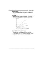
...diagram, when the CPU temperature reaches 60℃, the CPU fan speed for 3 PWM/℃ is 1 PWM/℃. Increasing the value of slope PWM will work under Smart Fan Function mode. S2: CPU temperature is 60℃, and PWM value is 2 PWM/℃. TA690G AM2 Start PWM Value When CPU temperature arrives to... the set value, the CPU fan will...
...diagram, when the CPU temperature reaches 60℃, the CPU fan speed for 3 PWM/℃ is 1 PWM/℃. Increasing the value of slope PWM will work under Smart Fan Function mode. S2: CPU temperature is 60℃, and PWM value is 2 PWM/℃. TA690G AM2 Start PWM Value When CPU temperature arrives to... the set value, the CPU fan will...
Setup Manual
Page 35
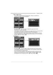
If the CPU temperature is lower than the upper limit, the status line color will change to . 35 FAN Speed By adjusting ... and the yellow line shows System Fan speed (if any one of CPU temperature. By adjusting , users can easily configure the lower limit of CPU temperature for CPU temperature and the green line shows present CPU temperature. In this diagram, the white line represents the upper limit which... set for system operating. There is a waveform to red, and a warning sound will trigger an alarm system automatically. TA690G AM2 CPU Temperature This column configures the...
If the CPU temperature is lower than the upper limit, the status line color will change to . 35 FAN Speed By adjusting ... and the yellow line shows System Fan speed (if any one of CPU temperature. By adjusting , users can easily configure the lower limit of CPU temperature for CPU temperature and the green line shows present CPU temperature. In this diagram, the white line represents the upper limit which... set for system operating. There is a waveform to red, and a warning sound will trigger an alarm system automatically. TA690G AM2 CPU Temperature This column configures the...

Setup Manual
Page 36
... limit by adjusting to . Users can set value, the status line will change into a red warning line, and a warning sound will alert you . If CPU voltage is only for present status reference. 36 Also, the system tray icon will change to monitor the... CPU operating voltage. VCore This item displays the CPU voltage, represented by a light green line. Motherboard Manual CPU/Battery Voltage i. Also, the system tray icon will change to monitor the status of power supply voltage ...
... limit by adjusting to . Users can set value, the status line will change into a red warning line, and a warning sound will alert you . If CPU voltage is only for present status reference. 36 Also, the system tray icon will change to monitor the... CPU operating voltage. VCore This item displays the CPU voltage, represented by a light green line. Motherboard Manual CPU/Battery Voltage i. Also, the system tray icon will change to monitor the status of power supply voltage ...

Setup Manual
Page 37
... column shows present CPU speed and overclocking percentage. Overclocking Configurations TA690G AM2 This diagram is designed for T-series Overclocking utility. This column shows the CPU speed information. H. B. F. Click on this button to reset all the overclock features to exit this button to default setting. Clicking on this overclock utility. D. Click on "Biostar" will appear when...
... column shows present CPU speed and overclocking percentage. Overclocking Configurations TA690G AM2 This diagram is designed for T-series Overclocking utility. This column shows the CPU speed information. H. B. F. Click on this button to reset all the overclock features to exit this button to default setting. Clicking on this overclock utility. D. Click on "Biostar" will appear when...

Setup Manual
Page 38
...And this function helps to increase VGA card performance. Interval: 1MHz. 38 B. Interval: 1. Motherboard Manual CPU Overclocking Settings: By adjusting can configure two items for CPU overclocking. CPU Ratio Range: 4~25. Memory Clock Frequency Choices: 100, 133, 200, 266, 333, 400, 533,... 1MHz. Memory Overclocking Settings: By adjusting can configure three items for Memory overclocking. Interval: 0.0125V. B. CPU Frequency Range: 200MHz~450MHz. Memory Voltage Range: 1.8V~2.8V. AGP/PCI-Express Overclocking Setting: By adjusting can configure VGA card overclocking....
...And this function helps to increase VGA card performance. Interval: 1MHz. 38 B. Interval: 1. Motherboard Manual CPU Overclocking Settings: By adjusting can configure two items for CPU overclocking. CPU Ratio Range: 4~25. Memory Clock Frequency Choices: 100, 133, 200, 266, 333, 400, 533,... 1MHz. Memory Overclocking Settings: By adjusting can configure three items for Memory overclocking. Interval: 0.0125V. B. CPU Frequency Range: 200MHz~450MHz. Memory Voltage Range: 1.8V~2.8V. AGP/PCI-Express Overclocking Setting: By adjusting can configure VGA card overclocking....

Setup Manual
Page 40
.... When Smart Fan Function activates for the first time, this button to re-calibrate the Fan speed. Calibrate: When changing CPU Fan or System Fan, click on this calibrate function would auto-run to illustrate the fan speed information. System Fan speed: Show current system Fan ... Smart Fan Function is done, the calibrating window will auto-close, and the main screen will pop-up to get upper and lower limitation of CPU Fan and System Fan. 2. When calibrating process is activated, screens will show new fan speed data. 40 Note: 1. i.
.... When Smart Fan Function activates for the first time, this button to re-calibrate the Fan speed. Calibrate: When changing CPU Fan or System Fan, click on this calibrate function would auto-run to illustrate the fan speed information. System Fan speed: Show current system Fan ... Smart Fan Function is done, the calibrating window will auto-close, and the main screen will pop-up to get upper and lower limitation of CPU Fan and System Fan. 2. When calibrating process is activated, screens will show new fan speed data. 40 Note: 1. i.

Setup Manual
Page 41
vi. Program Tool Bar: z About: Click on this button to exit this program. 41 z Minimize: Click on this button to minimize the program to system tray z Exit: Click on this button again to get program-related information. TA690G AM2 v. There will be pulling-meter besides the CPU Fan and System Fan, the CPU Fan and the System Fan speed can be adjusted by adjusting the Cursor Up or Down. Auto: If the green indicator is lit up . Click on this button to close Smart Fan Function, and a screen as below would pop-up , the Smart Fan Function is "On" (Default Setting).
vi. Program Tool Bar: z About: Click on this button to exit this program. 41 z Minimize: Click on this button to minimize the program to system tray z Exit: Click on this button again to get program-related information. TA690G AM2 v. There will be pulling-meter besides the CPU Fan and System Fan, the CPU Fan and the System Fan speed can be adjusted by adjusting the Cursor Up or Down. Auto: If the green indicator is lit up . Click on this button to close Smart Fan Function, and a screen as below would pop-up , the Smart Fan Function is "On" (Default Setting).

Setup Manual
Page 44
...is shown after boot-up No error found or video card beeps memory bad High-low siren sound CPU overheated System will work properly. 44 Download the Flash Utility "AWDFLASH.exe" from Biostar website. 4. Copy "AWDFLASH.exe" and respectively BIOS into floppy drive and press Enter. 6. System...system boot-up the system, it means the BIOS contents are corrupted. Confirm motherboard model and download the respectively BIOS from the Biostar website: www.biostar.com.tw 3. Motherboard Manual 6.2 AWARD BIOS BEEP CODE Beep Sound Meaning One long beep followed by virus, the Boot-Block ...
...is shown after boot-up No error found or video card beeps memory bad High-low siren sound CPU overheated System will work properly. 44 Download the Flash Utility "AWDFLASH.exe" from Biostar website. 4. Copy "AWDFLASH.exe" and respectively BIOS into floppy drive and press Enter. 6. System...system boot-up the system, it means the BIOS contents are corrupted. Confirm motherboard model and download the respectively BIOS from the Biostar website: www.biostar.com.tw 3. Motherboard Manual 6.2 AWARD BIOS BEEP CODE Beep Sound Meaning One long beep followed by virus, the Boot-Block ...

Setup Manual
Page 45
...automatically after power on system for seconds. 3. CPU fan speed is placed evenly with the CPU speed. After confirmed, please follow steps below to avoid a damage of the CPU, and the system may not power on the system again. 45 When the CPU is rotated normally. 3. Wait for seconds, that.... 2. Plug in the power cord and boot up the system. Remove the power cord from power supply for seconds. 3. Or you can: 1. TA690G AM2 B. The CPU cooler surface is fulfilling with the CPU surface. 2. CPU fan is over heated, the motherboard will shutdown automatically to relief the...
...automatically after power on system for seconds. 3. CPU fan speed is placed evenly with the CPU speed. After confirmed, please follow steps below to avoid a damage of the CPU, and the system may not power on the system again. 45 When the CPU is rotated normally. 3. Wait for seconds, that.... 2. Plug in the power cord and boot up the system. Remove the power cord from power supply for seconds. 3. Or you can: 1. TA690G AM2 B. The CPU cooler surface is fulfilling with the CPU surface. 2. CPU fan is over heated, the motherboard will shutdown automatically to relief the...


