
Setup Manual
Page 3
Before you start installing the motherboard, please make sure you follow the instructions below: „ Prepare a dry and stable working environment...flex the board. „ Do not leave any unfastened small parts inside the case after installation. CHAPTER 1: INTRODUCTION TA690G AM2 1.1 BEFORE YOU START Thank you take the motherboard out from dangerous area, such as heat source, humid air and water. 1.2 PACKAGE CHECKLIST HDD Cable X 1 Serial... edge, do not try to remove the static charge. „ Avoid touching the components on motherboard or the rear side of the board unless necessary.
Before you start installing the motherboard, please make sure you follow the instructions below: „ Prepare a dry and stable working environment...flex the board. „ Do not leave any unfastened small parts inside the case after installation. CHAPTER 1: INTRODUCTION TA690G AM2 1.1 BEFORE YOU START Thank you take the motherboard out from dangerous area, such as heat source, humid air and water. 1.2 PACKAGE CHECKLIST HDD Cable X 1 Serial... edge, do not try to remove the static charge. „ Avoid touching the components on motherboard or the rear side of the board unless necessary.

Setup Manual
Page 4
... DMA 33 / 66 / 100 / 133 Bus Master Mode supports PIO Mode 0~4, SATA II Integrated Serial ATA Controller Data transfer rates up to 3 Gb/s. Motherboard Manual 1.3 MOTHERBOARD FEATURES SPEC Socket AM2 AMD 64 Architecture enables 32 and 64 bit computing CPU AMD Athlon 64 / Athlon 64 FX / Athlon 64 Supports Hyper Transport and Cool...
... DMA 33 / 66 / 100 / 133 Bus Master Mode supports PIO Mode 0~4, SATA II Integrated Serial ATA Controller Data transfer rates up to 3 Gb/s. Motherboard Manual 1.3 MOTHERBOARD FEATURES SPEC Socket AM2 AMD 64 Architecture enables 32 and 64 bit computing CPU AMD Athlon 64 / Athlon 64 FX / Athlon 64 Supports Hyper Transport and Cool...

Setup Manual
Page 7
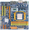
DVI-D VGA 1.5 MOTHERBOARD LAYOUT JKBMS1 JATXPWR2 JCFAN1 TA690G AM2 JATXPWR1 JTVOUT1 JHDMI DIMMA1 DIMMB1 DIMMA2 DIMMB2 Socket A M2 JUSB1 JUSBLAN1 JNFAN1 AMD 690G IDE1 FDD1 AUDIO1 LAN JAUDIOF1 PEX16_1 Codec PEX1_1 JSPDIF_OUT1 JSPDIF_IN1 JCDIN1 PCI1 BAT1 JCMOS1 AMD SB600 BIOS SATA2 SATA1 Super I/O JPRNT1 PCI2 JCOM1 JUSB2 JUSB3 LED_D1 LED_D2 SATA4 SATA3 JUSB4 JSFAN2 JPANEL1 PWRSW1 JSFAN1 RSTSW1 Note: ■ represents the 1st pin. 7
DVI-D VGA 1.5 MOTHERBOARD LAYOUT JKBMS1 JATXPWR2 JCFAN1 TA690G AM2 JATXPWR1 JTVOUT1 JHDMI DIMMA1 DIMMB1 DIMMA2 DIMMB2 Socket A M2 JUSB1 JUSBLAN1 JNFAN1 AMD 690G IDE1 FDD1 AUDIO1 LAN JAUDIOF1 PEX16_1 Codec PEX1_1 JSPDIF_OUT1 JSPDIF_IN1 JCDIN1 PCI1 BAT1 JCMOS1 AMD SB600 BIOS SATA2 SATA1 Super I/O JPRNT1 PCI2 JCOM1 JUSB2 JUSB3 LED_D1 LED_D2 SATA4 SATA3 JUSB4 JSFAN2 JPANEL1 PWRSW1 JSFAN1 RSTSW1 Note: ■ represents the 1st pin. 7

Setup Manual
Page 13
The IDE connector can connect a master and a slave drive, so you can connect up to two hard disk drives. 40 39 21 13 TA690G AM2 2.4 CONNECTORS AND SLOTS FDD1: Floppy Disk Connector The motherboard provides a standard floppy disk connector that provides PIO Mode 0~4, Bus Master, and Ultra DMA 33/66/100/133 functionality. This connector supports the provided floppy drive ribbon cables. 34 33 2 1 IDE1: Hard Disk Connector The motherboard has a 32-bit Enhanced PCI IDE Controller that supports 360K, 720K, 1.2M, 1.44M and 2.88M floppy disk types.
The IDE connector can connect a master and a slave drive, so you can connect up to two hard disk drives. 40 39 21 13 TA690G AM2 2.4 CONNECTORS AND SLOTS FDD1: Floppy Disk Connector The motherboard provides a standard floppy disk connector that provides PIO Mode 0~4, Bus Master, and Ultra DMA 33/66/100/133 functionality. This connector supports the provided floppy drive ribbon cables. 34 33 2 1 IDE1: Hard Disk Connector The motherboard has a 32-bit Enhanced PCI IDE Controller that supports 360K, 720K, 1.2M, 1.44M and 2.88M floppy disk types.

Setup Manual
Page 19
... 3 4 TXGround SATA4 SATA3 5 RX- 14 7 6 RX+ 7 Ground JPRNT1: Printer Port Connector This header allows you to SATA Controller with 4 channels SATA interface. TA690G AM2 SATA1~SATA4: Serial ATA Connectors The motherboard has a PCI to connector printer on the PC. 2 1 25 Pin Assignment 1 -Strobe 2 -ALF 3 Data 0 4 -Error 5 Data 1 6 -Init 7 Data 2 8 -Scltin 9 Data 3 10 Ground...
... 3 4 TXGround SATA4 SATA3 5 RX- 14 7 6 RX+ 7 Ground JPRNT1: Printer Port Connector This header allows you to SATA Controller with 4 channels SATA interface. TA690G AM2 SATA1~SATA4: Serial ATA Connectors The motherboard has a PCI to connector printer on the PC. 2 1 25 Pin Assignment 1 -Strobe 2 -ALF 3 Data 0 4 -Error 5 Data 1 6 -Init 7 Data 2 8 -Scltin 9 Data 3 10 Ground...

Setup Manual
Page 21
LED_D1 LED_D2 LED_D1 and LED_D2: These 2 LED indicate system power on the motherboard to the table below for different messages: LED_D1 ON ON OFF OFF LED_D2 ON OFF ON OFF Message Normal Memory Error VGA Error Abnormal: CPU / Chipset error. 21 On-Board LED Indicators There are 2 on-board buttons. Please refer to show system status. RSTSW1: This is an on -board Reset button. TA690G AM2 RSTSW1 PWRSW1 PWRSW1: This is an on -board Power Switch button. On-Board Buttons There are 2 LED indicators on diagnostics.
LED_D1 LED_D2 LED_D1 and LED_D2: These 2 LED indicate system power on the motherboard to the table below for different messages: LED_D1 ON ON OFF OFF LED_D2 ON OFF ON OFF Message Normal Memory Error VGA Error Abnormal: CPU / Chipset error. 21 On-Board LED Indicators There are 2 on-board buttons. Please refer to show system status. RSTSW1: This is an on -board Reset button. TA690G AM2 RSTSW1 PWRSW1 PWRSW1: This is an on -board Power Switch button. On-Board Buttons There are 2 LED indicators on diagnostics.

Setup Manual
Page 43
... driver, please click on each software title to launch the installation program. B. Note: You will list the software available for your motherboard and operating system. Click on the Driver icon. A. C. Manual Aside from http://www.adobe.com/products/acrobat/readstep2.html 43 Click...to open the manual file. The setup guide will need Acrobat Reader to browse for better system performance. CHAPTER 6: USEFUL HELP TA690G AM2 6.1 DRIVER INSTALLATION NOTE After you installed your operating system, please insert the Fully Setup Driver CD into your optical drive and ...
... driver, please click on each software title to launch the installation program. B. Note: You will list the software available for your motherboard and operating system. Click on the Driver icon. A. C. Manual Aside from http://www.adobe.com/products/acrobat/readstep2.html 43 Click...to open the manual file. The setup guide will need Acrobat Reader to browse for better system performance. CHAPTER 6: USEFUL HELP TA690G AM2 6.1 DRIVER INSTALLATION NOTE After you installed your operating system, please insert the Fully Setup Driver CD into your optical drive and ...

Setup Manual
Page 45
... power on the system again. 45 Wait for seconds, that means the CPU protection function has been activated. CPU fan speed is over heated, the motherboard will shutdown automatically to relief the CPU protection function. 1. In this case, please double check: 1. When the CPU is fulfilling with the CPU surface...
... power on the system again. 45 Wait for seconds, that means the CPU protection function has been activated. CPU fan speed is over heated, the motherboard will shutdown automatically to relief the CPU protection function. 1. In this case, please double check: 1. When the CPU is fulfilling with the CPU surface...


