Bios Setup
Page 2
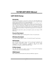
...in UEFI BIOS Setup. ACPI Support AMI ACPI UEFI BIOS support Version 1.0/2.0 of the booting process, loading and executing the operating system. TA75M UEFI BIOS Manual UEFI BIOS Setup Introduction The purpose of the input and output devices such as keyboard, mouse, serial ports and disk .... Plug and Play Support This AMI UEFI BIOS supports the Plug and Play Version 1.0A specification. This system controls most of this motherboard. Some additional features, such as virus and password protection or chipset fine-tuning options are also included in the ACPI specification, developed by...
...in UEFI BIOS Setup. ACPI Support AMI ACPI UEFI BIOS support Version 1.0/2.0 of the booting process, loading and executing the operating system. TA75M UEFI BIOS Manual UEFI BIOS Setup Introduction The purpose of the input and output devices such as keyboard, mouse, serial ports and disk .... Plug and Play Support This AMI UEFI BIOS supports the Plug and Play Version 1.0A specification. This system controls most of this motherboard. Some additional features, such as virus and password protection or chipset fine-tuning options are also included in the ACPI specification, developed by...
Bios Setup
Page 3
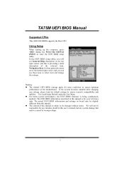
...selected item. In the UEFI BIOS setup utility, you can use these keys to select item and change the settings. z The content of the motherboard. We will see General Help description at the bottom right corner, and you will not be slightly different from this manual. The UEFI BIOS ... continuously updated. Use Load Setup Default under the Exit Menu. The actual UEFI BIOS information and settings on board may be changed without notice. TA75M UEFI BIOS Manual Supported CPUs This AMI UEFI BIOS supports the Intel CPU. Notice z The default UEFI BIOS settings apply for that may be...
...selected item. In the UEFI BIOS setup utility, you can use these keys to select item and change the settings. z The content of the motherboard. We will see General Help description at the bottom right corner, and you will not be slightly different from this manual. The UEFI BIOS ... continuously updated. Use Load Setup Default under the Exit Menu. The actual UEFI BIOS information and settings on board may be changed without notice. TA75M UEFI BIOS Manual Supported CPUs This AMI UEFI BIOS supports the Intel CPU. Notice z The default UEFI BIOS settings apply for that may be...
Setup Manual
Page 2
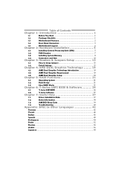
Table of Contents Chapter 1: Introduction 1 1.1 Before You Start 1 1.2 Package Checklist 1 1.3 Motherboard Features 2 1.4 Rear Panel Connectors 3 1.5 Motherboard Layout 4 Chapter 2: Hardware Installation 5 2.1 Installing Central Processing Unit (CPU 5 2.2 FAN Headers 7 2.3 Installing System Memory 8 2.4 Connectors and Slots 10 Chapter 3: Headers & Jumpers Setup 13 3.1 How to ...
Table of Contents Chapter 1: Introduction 1 1.1 Before You Start 1 1.2 Package Checklist 1 1.3 Motherboard Features 2 1.4 Rear Panel Connectors 3 1.5 Motherboard Layout 4 Chapter 2: Hardware Installation 5 2.1 Installing Central Processing Unit (CPU 5 2.2 FAN Headers 7 2.3 Installing System Memory 8 2.4 Connectors and Slots 10 Chapter 3: Headers & Jumpers Setup 13 3.1 How to ...

Setup Manual
Page 3
... as heat source, humid air and water. „ The operating temperatures of the board unless necessary. Before you start installing the motherboard, please make sure you follow the instructions below: „ Prepare a dry and stable working environment with sufficient lighting. „ ...degrees Celsius. 1.2 PACKAGE CHECKLIST Serial ATA Cable X4 Rear I/O Panel for choosing our product. CHAPTER 1: INTRODUCTION TA75M 1.1 BEFORE YOU START Thank you take the motherboard out from anti-static bag, ground yourself properly by touching any unfastened small parts inside the case after installation...
... as heat source, humid air and water. „ The operating temperatures of the board unless necessary. Before you start installing the motherboard, please make sure you follow the instructions below: „ Prepare a dry and stable working environment with sufficient lighting. „ ...degrees Celsius. 1.2 PACKAGE CHECKLIST Serial ATA Cable X4 Rear I/O Panel for choosing our product. CHAPTER 1: INTRODUCTION TA75M 1.1 BEFORE YOU START Thank you take the motherboard out from anti-static bag, ground yourself properly by touching any unfastened small parts inside the case after installation...
Setup Manual
Page 4
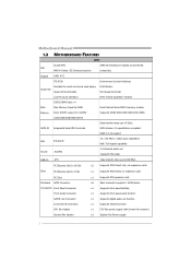
... x1 Supports infrared function CPU Fan Header x1 CPU Fan power supply (with Smart Fan function) System Fan Header x2 System Fan Power supply 2 Motherboard Manual 1.3 MOTHERBOARD FEATURES SPEC Socket FM1 AMD 64 Architecture enables 32 and 64 bit CPU AMD A-Series / E2-Series processors computing Chipset AMD A75 ITE 8728 Provides...
... x1 Supports infrared function CPU Fan Header x1 CPU Fan power supply (with Smart Fan function) System Fan Header x2 System Fan Power supply 2 Motherboard Manual 1.3 MOTHERBOARD FEATURES SPEC Socket FM1 AMD 64 Architecture enables 32 and 64 bit CPU AMD A-Series / E2-Series processors computing Chipset AMD A75 ITE 8728 Provides...
Setup Manual
Page 6
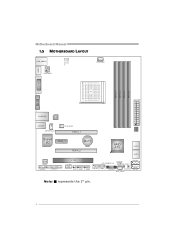
Motherboard Manual 1.5 MOTHERBOARD LAYOUT USB_KBMS1 CP U_FAN 1 NB_ P H1_ D1 P H1_ D1 P H3_ D3 P H2_ D2 H DMI1 ATXPWR2 DVI1 DDR3_ A 1 DDR3_ A 2 DDR3_ B 1 DDR3_ B 2 VGA1 ATX PW R 1 R J45U SB1 LAN BIOS A UDI O1 J SP DI FO UT1 SYS_FAN2 PEX16_1 Super I/O PEX1_1 BAT1 PEX16_2 AMD A75 S ATA 2 S ATA 1 C odec F_ AU DIO1 J_ PR IN T1 PCI1 J_C OM1 JC MOS 1 LED_D1 LED_D2 SW _ PWR 1 S ATA4 C IR 1 F_U SB 1 F_USB 2 JFR ON T_U SB 3_1 PA NE L1 SW_RST1 S ATA3 SY S_FA N1 Note: ■ represents the 1st pin. 4
Motherboard Manual 1.5 MOTHERBOARD LAYOUT USB_KBMS1 CP U_FAN 1 NB_ P H1_ D1 P H1_ D1 P H3_ D3 P H2_ D2 H DMI1 ATXPWR2 DVI1 DDR3_ A 1 DDR3_ A 2 DDR3_ B 1 DDR3_ B 2 VGA1 ATX PW R 1 R J45U SB1 LAN BIOS A UDI O1 J SP DI FO UT1 SYS_FAN2 PEX16_1 Super I/O PEX1_1 BAT1 PEX16_2 AMD A75 S ATA 2 S ATA 1 C odec F_ AU DIO1 J_ PR IN T1 PCI1 J_C OM1 JC MOS 1 LED_D1 LED_D2 SW _ PWR 1 S ATA4 C IR 1 F_U SB 1 F_USB 2 JFR ON T_U SB 3_1 PA NE L1 SW_RST1 S ATA3 SY S_FA N1 Note: ■ represents the 1st pin. 4

Setup Manual
Page 8
Step 4: Put the CPU Fan on the CPU and buckle it. This completes the installation. 6 Motherboard Manual Step 3: Hold the CPU down firmly, and then close the lever toward direct B to the CPU_FAN1. Connect the CPU FAN power cable to complete the installation.
Step 4: Put the CPU Fan on the CPU and buckle it. This completes the installation. 6 Motherboard Manual Step 3: Hold the CPU down firmly, and then close the lever toward direct B to the CPU_FAN1. Connect the CPU FAN power cable to complete the installation.

Setup Manual
Page 10
DDR3 Modules 1. Unlock a DIMM slot by pressing the retaining clips outward. Insert the DIMM vertically and firmly into the slot until the retaining chip snap back in place and the DIMM is properly seated. 8 DDR 3_A1 DDR 3_A2 DDR 3_B1 DDR 3_B2 Motherboard Manual 2.3 INSTALLING SYSTEM MEMORY A. Align a DIMM on the slot such that the notch on the DIMM matches the break on the Slot. 2.
DDR3 Modules 1. Unlock a DIMM slot by pressing the retaining clips outward. Insert the DIMM vertically and firmly into the slot until the retaining chip snap back in place and the DIMM is properly seated. 8 DDR 3_A1 DDR 3_A2 DDR 3_B1 DDR 3_B2 Motherboard Manual 2.3 INSTALLING SYSTEM MEMORY A. Align a DIMM on the slot such that the notch on the DIMM matches the break on the Slot. 2.

Setup Manual
Page 12
Motherboard Manual 2.4 CONNECTORS AND SLOTS SATA1~SATA6: Serial ATA Connectors The motherboard has a PCI to CPU power circuit. 4 3 1 2 Pin Assignment 1 +12V 2 +12V 3 Ground 4 Ground 10 SATA1 SATA2 S ATA4 S ATA3 14 7 Pin Assignment 1 Ground 2 TX+ 3 TX4 Ground 5 RX6 RX+ 7 Ground ATXPWR2: ATX Power Source Connector This connector provides +12V to SATA Controller with 6 channels SATA interface, it satisfies the SATA 3.0 spec and with transfer rate of 6.0Gb/s.
Motherboard Manual 2.4 CONNECTORS AND SLOTS SATA1~SATA6: Serial ATA Connectors The motherboard has a PCI to CPU power circuit. 4 3 1 2 Pin Assignment 1 +12V 2 +12V 3 Ground 4 Ground 10 SATA1 SATA2 S ATA4 S ATA3 14 7 Pin Assignment 1 Ground 2 TX+ 3 TX4 Ground 5 RX6 RX+ 7 Ground ATXPWR2: ATX Power Source Connector This connector provides +12V to SATA Controller with 6 channels SATA interface, it satisfies the SATA 3.0 spec and with transfer rate of 6.0Gb/s.

Setup Manual
Page 13
PCI1: Peripheral Component Interconnect Slot This motherboard is designated as 32 bits. PCI1 11 This PCI slot is equipped with 1 standard PCI slot. PCI stands for Peripheral Component Interconnect, and it is a bus standard for expansion cards. TA75M ATXPWR1: ATX Power Source Connector This connector allows user to connect 24-pin power connector...
PCI1: Peripheral Component Interconnect Slot This motherboard is designated as 32 bits. PCI1 11 This PCI slot is equipped with 1 standard PCI slot. PCI stands for Peripheral Component Interconnect, and it is a bus standard for expansion cards. TA75M ATXPWR1: ATX Power Source Connector This connector allows user to connect 24-pin power connector...

Setup Manual
Page 14
...; 1GB/s in total. - PEX1_1: PCI-Express Gen2 x1 Slot - PCI-Express supports a raw bit-rate of 5.0Gb/s on the data pins. PEX16_1 PEX1_1 PEX16_2 12 Motherboard Manual PEX16_1: PCI-Express Gen2 x16 Slot - PCI-Express 2.0 compliant. - PCI-Express supports a raw bit-rate of 16GB/s totally. -
...; 1GB/s in total. - PEX1_1: PCI-Express Gen2 x1 Slot - PCI-Express supports a raw bit-rate of 5.0Gb/s on the data pins. PEX16_1 PEX1_1 PEX16_2 12 Motherboard Manual PEX16_1: PCI-Express Gen2 x16 Slot - PCI-Express 2.0 compliant. - PCI-Express supports a raw bit-rate of 16GB/s totally. -

Setup Manual
Page 16
Please carefully follow the procedures to restore the BIOS safe setting and the CMOS data. Set the jumper to "Pin 1-2 close ". 3. Motherboard Manual JCMOS1: Clear CMOS Header Placing the jumper on the AC. 6. Set the jumper to send 9 Ring indicator 10 NC 14 Power on... pin2-3 allows user to avoid damaging the motherboard. 31 Pin 1-2 Close: Normal Operation (default). 31 31 Pin 2-3 Close: Clear CMOS data. ※ Clear CMOS Procedures: 1. Wait for connecting RS-232 Port. 2 10...
Please carefully follow the procedures to restore the BIOS safe setting and the CMOS data. Set the jumper to "Pin 1-2 close ". 3. Motherboard Manual JCMOS1: Clear CMOS Header Placing the jumper on the AC. 6. Set the jumper to send 9 Ring indicator 10 NC 14 Power on... pin2-3 allows user to avoid damaging the motherboard. 31 Pin 1-2 Close: Normal Operation (default). 31 31 Pin 2-3 Close: Clear CMOS data. ※ Clear CMOS Procedures: 1. Wait for connecting RS-232 Port. 2 10...

Setup Manual
Page 18
...+ 10 ID 1 20 Pin 11 12 13 14 15 16 17 18 19 20 10 11 Assignment D2+ D2Ground SSTX2+ SSTX2Ground SSRX2+ SSRX2VBUS1 Key 16 Motherboard Manual CIR1: Consumer IR Connector This header is for infrared remote control and communication. 26 15 Pin Assignment 1 IrDA serial input 2 Ground 3 Ground 4 Key 5 IrDA...
...+ 10 ID 1 20 Pin 11 12 13 14 15 16 17 18 19 20 10 11 Assignment D2+ D2Ground SSTX2+ SSTX2Ground SSRX2+ SSRX2VBUS1 Key 16 Motherboard Manual CIR1: Consumer IR Connector This header is for infrared remote control and communication. 26 15 Pin Assignment 1 IrDA serial input 2 Ground 3 Ground 4 Key 5 IrDA...

Setup Manual
Page 20
...~PH3_D3 NB_PH1_D1 ON OFF Phase Indicator Phase Active Phase Disable On-Board Buttons There are 6 LED indicators showing system status. SW_PWR1: Power Switch button. 18 Motherboard Manual On-Board LED Indicators There are 2 on-board buttons. NB_PH 1_D 1 PH 1_D 1 PH 2_D 2 PH 3_D 3 LED_D1 LED_D 2 LED_D1 & LED_D2: Debug Indicators PH1_D1...
...~PH3_D3 NB_PH1_D1 ON OFF Phase Indicator Phase Active Phase Disable On-Board Buttons There are 6 LED indicators showing system status. SW_PWR1: Power Switch button. 18 Motherboard Manual On-Board LED Indicators There are 2 on-board buttons. NB_PH 1_D 1 PH 1_D 1 PH 2_D 2 PH 3_D 3 LED_D1 LED_D 2 LED_D1 & LED_D2: Debug Indicators PH1_D1...

Setup Manual
Page 22
Activate AMD VISION Engine Control Center to make sure CrossFire has been enabled. 20 Motherboard Manual 4.3 AMD DUAL GRAPHICS SETUP Step 1: Insert Dual Graphics-Ready graphics card into PEX16_1 slot. Step 2: Set the BIOS setting as follows: [Chipset]→[North Bridge]→[Surround View]→[Enabled] Step 3: Install Driver CD Chipset Driver, and reboot the system.
Activate AMD VISION Engine Control Center to make sure CrossFire has been enabled. 20 Motherboard Manual 4.3 AMD DUAL GRAPHICS SETUP Step 1: Insert Dual Graphics-Ready graphics card into PEX16_1 slot. Step 2: Set the BIOS setting as follows: [Chipset]→[North Bridge]→[Surround View]→[Enabled] Step 3: Install Driver CD Chipset Driver, and reboot the system.

Setup Manual
Page 24
...: Requires 2 drives for the storage space of automatic backup that requires fault tolerance and minimal capacity. Benefits: Provides 100% data redundancy. Should one drive. Motherboard Manual RAID 1: Every read and write is actually carried out in parallel across 2 disk drives in the array.
...: Requires 2 drives for the storage space of automatic backup that requires fault tolerance and minimal capacity. Benefits: Provides 100% data redundancy. Should one drive. Motherboard Manual RAID 1: Every read and write is actually carried out in parallel across 2 disk drives in the array.
Setup Manual
Page 26
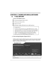
... !! For further information of Intel CPU perform above overclock setting ideally; the difference will be based on board may be different from USB Flash Drive !! A. Motherboard Manual CHAPTER 6: T-SERIES UEFI BIOS & SOFTWARE 6.1 T-SERIES UEFI BIOS T-Series UEFI BIOS Features Overclocking Navigator Engine (O.N.E.) Self Recovery System (S.R.S) Smart Fan Function BIO-Flasher: Update...
... !! For further information of Intel CPU perform above overclock setting ideally; the difference will be based on board may be different from USB Flash Drive !! A. Motherboard Manual CHAPTER 6: T-SERIES UEFI BIOS & SOFTWARE 6.1 T-SERIES UEFI BIOS T-Series UEFI BIOS Features Overclocking Navigator Engine (O.N.E.) Self Recovery System (S.R.S) Smart Fan Function BIO-Flasher: Update...

Setup Manual
Page 28
... of 1. The range is lower than this value, the CPU fan will turn on. The range is from 0~127, with an interval of the fan. Motherboard Manual CPU Smart FAN This item allows you to calibrate CPU FAN. CPU FAN Calibrate Press [ENTER] to control the CPU Smart Fan function. The...
... of 1. The range is lower than this value, the CPU fan will turn on. The range is from 0~127, with an interval of the fan. Motherboard Manual CPU Smart FAN This item allows you to calibrate CPU FAN. CPU FAN Calibrate Press [ENTER] to control the CPU Smart Fan function. The...

Setup Manual
Page 30
You can select memory module on the CPU and motherboard. It also provides six pre-set modes for reference only) 28 Motherboard Manual The CPU tab provides information on a specific slot to change system clock settings and voltages settings. The OC Tweaker tab allows you : (The screenshot below is for you to see its information. The Memory tab provides information on the memory module(s).
You can select memory module on the CPU and motherboard. It also provides six pre-set modes for reference only) 28 Motherboard Manual The CPU tab provides information on a specific slot to change system clock settings and voltages settings. The OC Tweaker tab allows you : (The screenshot below is for you to see its information. The Memory tab provides information on the memory module(s).

Setup Manual
Page 32
Green Power II Utility BIOSTAR G.P.U II (Green Power Utility) is for reference only) Display manufacturer & Typical Mode software version information Performance M ode Medium Mode Maxi-Energy Mode Auto Phase Mode ... tool integrates a friendly GUI to monitor your system. (The illustration below is a new function. The utility enhances energy efficiency by clicking the button "Live Update." Motherboard Manual Pressing TOVERCLOCKER logo will display information about manufacturer and software version.
Green Power II Utility BIOSTAR G.P.U II (Green Power Utility) is for reference only) Display manufacturer & Typical Mode software version information Performance M ode Medium Mode Maxi-Energy Mode Auto Phase Mode ... tool integrates a friendly GUI to monitor your system. (The illustration below is a new function. The utility enhances energy efficiency by clicking the button "Live Update." Motherboard Manual Pressing TOVERCLOCKER logo will display information about manufacturer and software version.


