
Setup Manual
Page 2
... 1: Introduction 1 1.1 Before You Start 1 1.2 Package Checklist 1 1.3 Motherboard Features 2 1.4 Rear Panel Connectors 3 1.5 Motherboard Layout 4 Chapter 2: Hardware Installation 5 2.1 Installing Central Processing Unit (CPU 5 2.2 FAN Headers 7 2.3 Installing System Memory 8 2.4 Connectors and Slots 10 Chapter 3: Headers & Jumpers Setup 13 3.1 How to Setup Jumpers 13 3.2 Detail Settings 13 Chapter 4: CrossFireX Function 20 4.1 CrossFireX Introduction 20 4.2 CrossFireX...
... 1: Introduction 1 1.1 Before You Start 1 1.2 Package Checklist 1 1.3 Motherboard Features 2 1.4 Rear Panel Connectors 3 1.5 Motherboard Layout 4 Chapter 2: Hardware Installation 5 2.1 Installing Central Processing Unit (CPU 5 2.2 FAN Headers 7 2.3 Installing System Memory 8 2.4 Connectors and Slots 10 Chapter 3: Headers & Jumpers Setup 13 3.1 How to Setup Jumpers 13 3.2 Detail Settings 13 Chapter 4: CrossFireX Function 20 4.1 CrossFireX Introduction 20 4.2 CrossFireX...

Setup Manual
Page 4
... I/O functionality H/W Monitor Fan Speed Controller Low Pin Count Interface ITE's "Smart Guardian" function Main DDR3 DIMM Slots x 4 Max Memory Capacity 32GB Dual Channel Mode DDR3 memory module Supports DDR3 800/1066/1333/1600/1866 Memory Each DIMM supports 512MB/ 1GB/2GB/4GB/8GB DDR3 Supports DDR3 2000 (OC) Registered DIMM and ECC DIMM...
... I/O functionality H/W Monitor Fan Speed Controller Low Pin Count Interface ITE's "Smart Guardian" function Main DDR3 DIMM Slots x 4 Max Memory Capacity 32GB Dual Channel Mode DDR3 memory module Supports DDR3 800/1066/1333/1600/1866 Memory Each DIMM supports 512MB/ 1GB/2GB/4GB/8GB DDR3 Supports DDR3 2000 (OC) Registered DIMM and ECC DIMM...
Setup Manual
Page 10
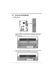
DDR3 Modules 1. Insert the DIMM vertically and firmly into the slot until the retaining chip snap back in place and the DIMM is properly seated. 8 Align a DIMM on the slot such that the notch on the DIMM matches the break on the Slot. 2. DDR 3_A1 DDR 3_A2 DDR 3_B1 DDR 3_B2 Motherboard Manual 2.3 INSTALLING SYSTEM MEMORY A. Unlock a DIMM slot by pressing the retaining clips outward.
DDR3 Modules 1. Insert the DIMM vertically and firmly into the slot until the retaining chip snap back in place and the DIMM is properly seated. 8 Align a DIMM on the slot such that the notch on the DIMM matches the break on the Slot. 2. DDR 3_A1 DDR 3_A2 DDR 3_B1 DDR 3_B2 Motherboard Manual 2.3 INSTALLING SYSTEM MEMORY A. Unlock a DIMM slot by pressing the retaining clips outward.

Setup Manual
Page 11
... requirements to activate Dual Channel function: Install memory module of the memory module must be the same (x8 or x16) Note: Memory module must be installed in the table. C. Dual Channel Status DDR3_A1 DDR3_A2 DDR3_B1 DDR3_B2 Enabled X O X O Enabled O O O O (O means memory installed, X means memory not installed.) The DRAM bus width of ...the same density in pairs, shown in DDR3-A2 or DDR3-B2 to boot the system. 9 Memory Capacity DIMM Socket Location DDR3_A1 DDR3_A2 DDR3_B1 DDR3_B2 DDR3 Module 512MB/1GB/2GB/4GB/8GB 512MB/1GB/2GB/4GB/8GB 512MB/1GB/2GB...
... requirements to activate Dual Channel function: Install memory module of the memory module must be the same (x8 or x16) Note: Memory module must be installed in the table. C. Dual Channel Status DDR3_A1 DDR3_A2 DDR3_B1 DDR3_B2 Enabled X O X O Enabled O O O O (O means memory installed, X means memory not installed.) The DRAM bus width of ...the same density in pairs, shown in DDR3-A2 or DDR3-B2 to boot the system. 9 Memory Capacity DIMM Socket Location DDR3_A1 DDR3_A2 DDR3_B1 DDR3_B2 DDR3 Module 512MB/1GB/2GB/4GB/8GB 512MB/1GB/2GB/4GB/8GB 512MB/1GB/2GB...

Setup Manual
Page 27
... all types of setting up the UEFI BIOS, please refer to customize personal overclock settings, such as Manual Voltage System, Manual Memory System, Manual MCT System, and Manual G.P.U System, etc. For further information of Intel CPU perform above overclock setting ideally;...Manual in this manual. The UEFI BIOS information described below in the Setup CD. CHAPTER 6: T-SERIES BIOS & SOFTWARE 6.1 T-SERIES BIOS TA990FXE T-Series UEFI BIOS Features Overclocking Navigator Engine (O.N.E.) Self Recovery System (S.R.S) Smart Fan Function BIO-Flasher: Update UEFI BIOS file from this ...
... all types of setting up the UEFI BIOS, please refer to customize personal overclock settings, such as Manual Voltage System, Manual Memory System, Manual MCT System, and Manual G.P.U System, etc. For further information of Intel CPU perform above overclock setting ideally;...Manual in this manual. The UEFI BIOS information described below in the Setup CD. CHAPTER 6: T-SERIES BIOS & SOFTWARE 6.1 T-SERIES BIOS TA990FXE T-Series UEFI BIOS Features Overclocking Navigator Engine (O.N.E.) Self Recovery System (S.R.S) Smart Fan Function BIO-Flasher: Update UEFI BIOS file from this ...

Setup Manual
Page 30
... unlimitedly, and pre-set OC modes are for monitoring system status.This utility also allows you will see the software icon showing on CPU and Memory. Insert the Setup CD to launch it. Motherboard Manual 6.2 T-SERIES SOFTWARE Installing T-Series Software 1.
... unlimitedly, and pre-set OC modes are for monitoring system status.This utility also allows you will see the software icon showing on CPU and Memory. Insert the Setup CD to launch it. Motherboard Manual 6.2 T-SERIES SOFTWARE Installing T-Series Software 1.

Setup Manual
Page 31
The OC Tweaker tab allows you : 29 TA990FXE The CPU tab provides information on the memory module(s). The Memory tab provides information on the CPU and motherboard. It also provides six pre-set modes for you to see its information. You can select memory module on a specific slot to change system clock settings and voltages settings.
The OC Tweaker tab allows you : 29 TA990FXE The CPU tab provides information on the memory module(s). The Memory tab provides information on the CPU and motherboard. It also provides six pre-set modes for you to see its information. You can select memory module on a specific slot to change system clock settings and voltages settings.

Setup Manual
Page 35
.... Provid e the name of your system. *Select your confirmation; A warning dialog would like to send t he copy to. *Provid e the name of the memory module ma nufa ct u rer. This utility will see a saving dialog appears asking you to enter file name. 33 Without this dialog. Provid e the e-ma... il address that helps you will collect the system information which would be able to send out the mail. TA990FXE eHot-Line (Optional) eHot-Line is useful for your area or the are a close to yo u. and then you to contact with our Tech...
.... Provid e the name of your system. *Select your confirmation; A warning dialog would like to send t he copy to. *Provid e the name of the memory module ma nufa ct u rer. This utility will see a saving dialog appears asking you to enter file name. 33 Without this dialog. Provid e the e-ma... il address that helps you will collect the system information which would be able to send out the mail. TA990FXE eHot-Line (Optional) eHot-Line is useful for your area or the are a close to yo u. and then you to contact with our Tech...

Setup Manual
Page 42
... video adapter is an add-in flash device) POST BIOS Beep Codes Number of Beeps Description 1 Memory refresh timer error 3 Base memory read/write test error 6 Keyboard controller BAT command failed 7 General exception error (processor exception interrupt error) 8 Display... memory error (system video adapter) Troubleshooting POST BIOS Beep Codes Number of Beeps Troubleshooting Action 1, 3 Reseat the memory, or replace with the system. z If beep codes are not generated when all...
... video adapter is an add-in flash device) POST BIOS Beep Codes Number of Beeps Description 1 Memory refresh timer error 3 Base memory read/write test error 6 Keyboard controller BAT command failed 7 General exception error (processor exception interrupt error) 8 Display... memory error (system video adapter) Troubleshooting POST BIOS Beep Codes Number of Beeps Troubleshooting Action 1, 3 Reseat the memory, or replace with the system. z If beep codes are not generated when all...

Setup Manual
Page 43
7.4 AMI BIOS POST CODE TA990FXE Checkpoint 03 04 05 06 07 08 C0 C1 C2 C5 C6 C7 0A 0B 0C 0E 13 20 24 2A 2C 2E 31 33 ... more information. Traps the INT09h vector, so that are based on KBC. See DIM Code Checkpoints section of different Input Devices. Initializes different devices. Allocate memory for ADM. Initialize language and font modules for ADM module and uncompress it. Initializes the silent boot module.
7.4 AMI BIOS POST CODE TA990FXE Checkpoint 03 04 05 06 07 08 C0 C1 C2 C5 C6 C7 0A 0B 0C 0E 13 20 24 2A 2C 2E 31 33 ... more information. Traps the INT09h vector, so that are based on KBC. See DIM Code Checkpoints section of different Input Devices. Initializes different devices. Allocate memory for ADM. Initialize language and font modules for ADM module and uncompress it. Initializes the silent boot module.

Setup Manual
Page 44
...through DIM. USB controllers are initialized at config display if needed before boot, which includes the programming of the MTRR's. Display total memory in the system. 3C Mid POST initialization of chipset registers. 8D Build ACPI tables (if ACPI is supported). 8E Program the ... vector and INT09h vector. AB Prepare BBS for ACPI. A1 Clean-up work needed . A4 Initialize runtime language module. Programming the memory hole or any OEM specific information. Check boot password if installed. 8C Late POST initialization of chipset registers. Takes care of chipset...
...through DIM. USB controllers are initialized at config display if needed before boot, which includes the programming of the MTRR's. Display total memory in the system. 3C Mid POST initialization of chipset registers. 8D Build ACPI tables (if ACPI is supported). 8E Program the ... vector and INT09h vector. AB Prepare BBS for ACPI. A1 Clean-up work needed . A4 Initialize runtime language module. Programming the memory hole or any OEM specific information. Check boot password if installed. 8C Late POST initialization of chipset registers. Takes care of chipset...

Bios Manual
Page 4
BIOS Information Shows system information including UEFI BIOS version, Project Code, Model Name, Build Date, etc. System Date Set the system date. System Time Set the system internal clock. 3 Note that the 'Day' automatically changes when you enter AMI UEFI BIOS Setup Utility, the Main Menu will be excluded. Total Memory Shows system memory size, VGA shard memory will appear on the screen providing an overview of the basic system information. TA990FXE UEFI BIOS Manual 1 Main Menu Once you set the date.
BIOS Information Shows system information including UEFI BIOS version, Project Code, Model Name, Build Date, etc. System Date Set the system date. System Time Set the system internal clock. 3 Note that the 'Day' automatically changes when you enter AMI UEFI BIOS Setup Utility, the Main Menu will be excluded. Total Memory Shows system memory size, VGA shard memory will appear on the screen providing an overview of the basic system information. TA990FXE UEFI BIOS Manual 1 Main Menu Once you set the date.

Bios Manual
Page 27
CPU HT Over Voltage This item allows you to select NB HT Voltage Control. 26 NB HT Over Voltage This item allows you to select NB Voltage Control. Memory Over Voltage This item allows you to select CPU HT Voltage Control. NB Over Voltage This item allows you to select CPU-NB Voltage Control. SB Over Voltage This item allows you to select Memory Voltage Control. CPU-NB Over Voltage This item allows you to select CPU Voltage Control. TA990FXE UEFI BIOS Manual CPU Vcore This item allows you to select SB Voltage Control.
CPU HT Over Voltage This item allows you to select NB HT Voltage Control. 26 NB HT Over Voltage This item allows you to select NB Voltage Control. Memory Over Voltage This item allows you to select CPU HT Voltage Control. NB Over Voltage This item allows you to select CPU-NB Voltage Control. SB Over Voltage This item allows you to select Memory Voltage Control. CPU-NB Over Voltage This item allows you to select CPU Voltage Control. TA990FXE UEFI BIOS Manual CPU Vcore This item allows you to select SB Voltage Control.
Bios Manual
Page 28
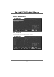
TA990FXE UEFI BIOS Manual BIOSTAR Memory Insight DDR3_A1/A2/B1/B2 These items display SPD information of DDR3 memory. 27
TA990FXE UEFI BIOS Manual BIOSTAR Memory Insight DDR3_A1/A2/B1/B2 These items display SPD information of DDR3 memory. 27

Bios Manual
Page 30
... value. Options: DDR 800 (Default) / DDR 1066 / DDR 1333 / DDR 1600 DRAM Timing Mode This item allows you to select the DRAM Frequency programming method. TA990FXE UEFI BIOS Manual MCT Timing Mode This item allows you to set the...
... value. Options: DDR 800 (Default) / DDR 1066 / DDR 1333 / DDR 1600 DRAM Timing Mode This item allows you to select the DRAM Frequency programming method. TA990FXE UEFI BIOS Manual MCT Timing Mode This item allows you to set the...

Bios Manual
Page 31
Options: Auto (Default) / Disabled Channel Interleaving This item allows you to improve memory performance. Options: Auto (Default) / Disabled 30 TA990FXE UEFI BIOS Manual TWR Options: Auto (Default) / 5~8 / 10 / 12 CLK TRRD Options: Auto (Default) / 4~7 CLK TWT R Options: Auto (Default) / 4~7 CLK MCT Configuration Bank Interleaving Bank Interleaving is an advanced chipset technique used to control the DDR3 dual-channel function. Memory interleaving increases bandwidth by allowing simultaneous access to more than one piece of memory.
Options: Auto (Default) / Disabled Channel Interleaving This item allows you to improve memory performance. Options: Auto (Default) / Disabled 30 TA990FXE UEFI BIOS Manual TWR Options: Auto (Default) / 5~8 / 10 / 12 CLK TRRD Options: Auto (Default) / 4~7 CLK TWT R Options: Auto (Default) / 4~7 CLK MCT Configuration Bank Interleaving Bank Interleaving is an advanced chipset technique used to control the DDR3 dual-channel function. Memory interleaving increases bandwidth by allowing simultaneous access to more than one piece of memory.

Bios Manual
Page 32
... Tristate function in dual-channel operation. Options: Disabled (Default) / Enabled Memory Hole Remapping This item allows you to DIMMs even memory slots are installed, using unganged mode can still make it run in C3 Mode. TA990FXE UEFI BIOS Manual Clock to All DIMMs This item enables unused clocks to... enable or disable the remapping of the overlapped PCI memory above the total physical memory. If two DRAM modules with different size are not populated....
... Tristate function in dual-channel operation. Options: Disabled (Default) / Enabled Memory Hole Remapping This item allows you to DIMMs even memory slots are installed, using unganged mode can still make it run in C3 Mode. TA990FXE UEFI BIOS Manual Clock to All DIMMs This item enables unused clocks to... enable or disable the remapping of the overlapped PCI memory above the total physical memory. If two DRAM modules with different size are not populated....


