

TForce 6100 user's manual
Page 2
... 754...1 C. About FAN Headers ...2 2.2 SYSTEM MEMORY...2 A. DDR Installation Notice...3 D. Card and I CHAPTER 1: INTRODUCTION ...1 1.1 MOTHERBOARD FEATURES ...1 1.2 LAYOUT AND COMPONENTS: TFORCE 6100-939...2 1.3 LAYOUT AND COMPONENTS: TFORCE 6100 ...3 CHAPTER 2: HARDWARE INSTALLATIONS ...1 2.1 CPU ASSEMBLY ...1 A. Connectors and Headers:...6 CHAPTER 3: USEFUL HELP...12 3.1 AWARD BIOS BEEP ...19 RUSSIAN ...20 ARABIC ...21 JAPANESE ...22 ii User's Manual Biostar T-Series TForce 6100-939/ TForce 6100 PACKAGE CHECKLIST ...I /O Slots:...4 B. Memory Space...3 C.
... 754...1 C. About FAN Headers ...2 2.2 SYSTEM MEMORY...2 A. DDR Installation Notice...3 D. Card and I CHAPTER 1: INTRODUCTION ...1 1.1 MOTHERBOARD FEATURES ...1 1.2 LAYOUT AND COMPONENTS: TFORCE 6100-939...2 1.3 LAYOUT AND COMPONENTS: TFORCE 6100 ...3 CHAPTER 2: HARDWARE INSTALLATIONS ...1 2.1 CPU ASSEMBLY ...1 A. Connectors and Headers:...6 CHAPTER 3: USEFUL HELP...12 3.1 AWARD BIOS BEEP ...19 RUSSIAN ...20 ARABIC ...21 JAPANESE ...22 ii User's Manual Biostar T-Series TForce 6100-939/ TForce 6100 PACKAGE CHECKLIST ...I /O Slots:...4 B. Memory Space...3 C.

TForce 6100 user's manual
Page 3
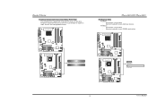
...to 3Gb/s. Maximum memory space is 2GB, supporting 2 DIMM sockets. TForce 6100 CPU Supports Socket 754. Two PCI slots. Back Panel I /O Chip: ITE IT8712F. Biostar T-Series Chapter 1: Introduction 1.1 MOTHERBOARD FEATURES TForce 6100-939 CPU Supports Socket 939. Supports HyperTransport Technlology up to 2000MT/s. Note... Memory Supports Dual Channel DDR. Supports DDR 266/333/400. Supports AMD Sempron processor. TForce 6100-939/ TForce 6100 Chipset North Bridge: NVIDIA Geforce6100. Supports AMD Athlon 64 FX / Athlon 64 /Athlon 64 X2 processors.
...to 3Gb/s. Maximum memory space is 2GB, supporting 2 DIMM sockets. TForce 6100 CPU Supports Socket 754. Two PCI slots. Back Panel I /O Chip: ITE IT8712F. Biostar T-Series Chapter 1: Introduction 1.1 MOTHERBOARD FEATURES TForce 6100-939 CPU Supports Socket 939. Supports HyperTransport Technlology up to 2000MT/s. Note... Memory Supports Dual Channel DDR. Supports DDR 266/333/400. Supports AMD Sempron processor. TForce 6100-939/ TForce 6100 Chipset North Bridge: NVIDIA Geforce6100. Supports AMD Athlon 64 FX / Athlon 64 /Athlon 64 X2 processors.

TForce 6100 user's manual
Page 9
... connector that provide PIO Mode 0~4, Bus Master, and Ultra DMA 33/66/100/133 functionality. Biostar T-Series 2.3 PERIPHERALS A. It has two HDD connectors IDE1 (primary) and IDE2 (secondary). TForce 6100-939 TForce 6100-939/ TForce 6100 Hard Disk Connectors: IDE1/IDE2 The motherboard has two 32-bit Enhanced PCI IDE Controllers that supports 360K, 720K, 1.2M, 1.44M and...
... connector that provide PIO Mode 0~4, Bus Master, and Ultra DMA 33/66/100/133 functionality. Biostar T-Series 2.3 PERIPHERALS A. It has two HDD connectors IDE1 (primary) and IDE2 (secondary). TForce 6100-939 TForce 6100-939/ TForce 6100 Hard Disk Connectors: IDE1/IDE2 The motherboard has two 32-bit Enhanced PCI IDE Controllers that supports 360K, 720K, 1.2M, 1.44M and...
TForce 6100 user's manual
Page 10
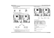
... Peripheral Component Interconnect, and it is designated as 32 bits. PCI Express 1.0a compliant. - TForce 6100-939 TForce 6100 PCI1 PCI2 TForce 6100 PCI-EX1_1 PCI-EX16 5 User's Manual Biostar T-Series Peripheral Component Interconnect Slots: PCI1~PCI2 This motherboard is up to 250MB/s per direction. PCI Express 1.0a compliant. - TForce 6100-939 TForce 6100-939/ TForce 6100 PCI-Express Slots PCI-EX16: - PCI-EX1_1: -
... Peripheral Component Interconnect, and it is designated as 32 bits. PCI Express 1.0a compliant. - TForce 6100-939 TForce 6100 PCI1 PCI2 TForce 6100 PCI-EX1_1 PCI-EX16 5 User's Manual Biostar T-Series Peripheral Component Interconnect Slots: PCI1~PCI2 This motherboard is up to 250MB/s per direction. PCI Express 1.0a compliant. - TForce 6100-939 TForce 6100-939/ TForce 6100 PCI-Express Slots PCI-EX16: - PCI-EX1_1: -
TForce 6100 user's manual
Page 11
...RSTSW2 RSTSW2 PWRSW1 LED_D1 LED_D2 LED_DIMM LED_PWR LED_D1 and LED_D2: These 2 LED indicate system power on . When the jumper cap is an on the motherboard to 3V. (Consulting your DDR supports up jumpers. RSTSW2: This is placed on -board Power Switch button. The default setting is activated normally... the system is placed on Pin 1-2, memory voltage will be fixed at 3.3V automatically, and can be adjusted under CMOS setup. 2. TForce 6100-939 TForce 6100 JDDR_OV>3V 13 13 31 31 13 31 Pin 1-2 Close Pin 2-3 Close (Default) Note: 1. Biostar T-Series B.
...RSTSW2 RSTSW2 PWRSW1 LED_D1 LED_D2 LED_DIMM LED_PWR LED_D1 and LED_D2: These 2 LED indicate system power on . When the jumper cap is an on the motherboard to 3V. (Consulting your DDR supports up jumpers. RSTSW2: This is placed on -board Power Switch button. The default setting is activated normally... the system is placed on Pin 1-2, memory voltage will be fixed at 3.3V automatically, and can be adjusted under CMOS setup. 2. TForce 6100-939 TForce 6100 JDDR_OV>3V 13 13 31 31 13 31 Pin 1-2 Close Pin 2-3 Close (Default) Note: 1. Biostar T-Series B.

TForce 6100 user's manual
Page 14
It will allow user to connect with transfer rate of 3.0 Gb/s. TForce 6100-939 TForce 6100 JAUDIO2 1 JFAUDIO1 2 13 Pin Assignment 1 MIC-in/ Stereo MIC-in R 2 Ground 3 Stereo MIC-in L 4 Audio power 5 Right line-...output headers on back panel audio connectors. TForce 6100-939 TForce 6100 TForce 6100-939/ TForce 6100 Serial ATA Connectors: JSATA1~JSATA2 The motherboard has an SATA Controller in (optional) JSATA1 JSATA2 1 47 Pin Assignment 1 Ground 2 TX+ 3 TX- 4 Ground 5 RX- 6 RX+ 7 Ground 9 User's Manual Biostar T-Series Front Panel Audio-out Header: ...
It will allow user to connect with transfer rate of 3.0 Gb/s. TForce 6100-939 TForce 6100 JAUDIO2 1 JFAUDIO1 2 13 Pin Assignment 1 MIC-in/ Stereo MIC-in R 2 Ground 3 Stereo MIC-in L 4 Audio power 5 Right line-...output headers on back panel audio connectors. TForce 6100-939 TForce 6100 TForce 6100-939/ TForce 6100 Serial ATA Connectors: JSATA1~JSATA2 The motherboard has an SATA Controller in (optional) JSATA1 JSATA2 1 47 Pin Assignment 1 Ground 2 TX+ 3 TX- 4 Ground 5 RX- 6 RX+ 7 Ground 9 User's Manual Biostar T-Series Front Panel Audio-out Header: ...

TForce 6100 user's manual
Page 15
...TForce 6100-939 JKBMSV1 1 3 1 3 Pin 1-2 Close 1 3 Pin 2-3 Close Note: In order to "Pin 1-2 Close". 5. Set the jumper to support this function "Power-on system via keyboard and mouse", "JKBMSV1" jumper cap should be placed on Pin 2-3. 10 User's Manual Wait for PS/2 keyboard and mouse.. Set the jumper to avoid damaging the motherboard... Biostar T-Series Clear CMOS Header: JCMOS1 By placing the jumper on pin 2-3, it allows user to restore the BIOS safe setting and the CMOS data, please carefully follow the procedures to "Pin 2-3 Close". 3. TForce 6100-939 TForce 6100 JCMOS1...
...TForce 6100-939 JKBMSV1 1 3 1 3 Pin 1-2 Close 1 3 Pin 2-3 Close Note: In order to "Pin 1-2 Close". 5. Set the jumper to support this function "Power-on system via keyboard and mouse", "JKBMSV1" jumper cap should be placed on Pin 2-3. 10 User's Manual Wait for PS/2 keyboard and mouse.. Set the jumper to avoid damaging the motherboard... Biostar T-Series Clear CMOS Header: JCMOS1 By placing the jumper on pin 2-3, it allows user to restore the BIOS safe setting and the CMOS data, please carefully follow the procedures to "Pin 2-3 Close". 3. TForce 6100-939 TForce 6100 JCMOS1...

TForce 6100 user's manual
Page 17
Confirm motherboard model and download the respective BIOS from the Biostar website: www.biostar.com.tw 3. Copy "AWDFLASH.exe" and respective BIOS onto floppy disk. 5. Insert the bootable disk into floppy drive and press Enter. 6. System...shut down automatically One Short beep when system boots-up of the system, it means the BIOS contents are corrupted. TForce 6100-939 TForce 6100 JSPDIF_OUT 3 1 Pin Assignment 1 +5V 2 SPDIF OUT 3 Ground TForce 6100-939/ TForce 6100 CHAPTER 3: USEFUL HELP 3.1 AWARD BIOS BEEP CODE Beep Sound Meaning One long beep followed by a virus, the ...
Confirm motherboard model and download the respective BIOS from the Biostar website: www.biostar.com.tw 3. Copy "AWDFLASH.exe" and respective BIOS onto floppy disk. 5. Insert the bootable disk into floppy drive and press Enter. 6. System...shut down automatically One Short beep when system boots-up of the system, it means the BIOS contents are corrupted. TForce 6100-939 TForce 6100 JSPDIF_OUT 3 1 Pin Assignment 1 +5V 2 SPDIF OUT 3 Ground TForce 6100-939/ TForce 6100 CHAPTER 3: USEFUL HELP 3.1 AWARD BIOS BEEP CODE Beep Sound Meaning One long beep followed by a virus, the ...

TForce 6100 user's manual
Page 18
...Hard disk can be used but booting from optical drive. 1. Reformat the hard drive. TForce 6100-939/ TForce 6100 3.3 TROUBLESHOOTING Problem Solution 1. check the drive type in . Backing up data and ... setup. inside power supply does not 2. Make sure power cable is over heated, the motherboard will not power on . Back up the hard drive is in setup. Review system's...on the system again. After confirmation, please follow the steps below to disk controller board. Biostar T-Series B. CPU fan speed is rotating normally. 3. Remove the power cord from optical drive...
...Hard disk can be used but booting from optical drive. 1. Reformat the hard drive. TForce 6100-939/ TForce 6100 3.3 TROUBLESHOOTING Problem Solution 1. check the drive type in . Backing up data and ... setup. inside power supply does not 2. Make sure power cable is over heated, the motherboard will not power on . Back up the hard drive is in setup. Review system's...on the system again. After confirmation, please follow the steps below to disk controller board. Biostar T-Series B. CPU fan speed is rotating normally. 3. Remove the power cord from optical drive...


