

TForce 6100 user's manual
Page 2
...Processing Unit (CPU) for Socket 754...1 C. Memory Space...3 C. BIOS Update...12 B. Card and I CHAPTER 1: INTRODUCTION ...1 1.1 MOTHERBOARD FEATURES ...1 1.2 LAYOUT AND COMPONENTS: TFORCE 6100-939...2 1.3 LAYOUT AND COMPONENTS: TFORCE 6100 ...3 CHAPTER 2: HARDWARE INSTALLATIONS... DDR Modules ...3 B. DDR Installation Notice...3 D. Central Processing Unit (CPU) for Socket 939...1 B. About FAN Headers ...2 2.2 SYSTEM MEMORY...2 A. Biostar T-Series TForce 6100-939/ TForce 6100 PACKAGE CHECKLIST ...I /O Slots:...4 B. Connectors and Headers:...6 CHAPTER 3: USEFUL HELP...12...
...Processing Unit (CPU) for Socket 754...1 C. Memory Space...3 C. BIOS Update...12 B. Card and I CHAPTER 1: INTRODUCTION ...1 1.1 MOTHERBOARD FEATURES ...1 1.2 LAYOUT AND COMPONENTS: TFORCE 6100-939...2 1.3 LAYOUT AND COMPONENTS: TFORCE 6100 ...3 CHAPTER 2: HARDWARE INSTALLATIONS... DDR Modules ...3 B. DDR Installation Notice...3 D. Central Processing Unit (CPU) for Socket 939...1 B. About FAN Headers ...2 2.2 SYSTEM MEMORY...2 A. Biostar T-Series TForce 6100-939/ TForce 6100 PACKAGE CHECKLIST ...I /O Slots:...4 B. Connectors and Headers:...6 CHAPTER 3: USEFUL HELP...12...

TForce 6100 user's manual
Page 3
... connector. 1 User's Manual Supports AMD Sempron processor. Internal On-board Slots and Connectors One PCI-Express X1 slot. TForce 6100 CPU Supports Socket 754. Environment Control initiatives, H/W Monitor Fan Speed Controller ITE's "Smart Guardian" function IDE 2 on-board connectors support 4 IDE disk drives. Biostar T-Series Chapter 1: Introduction 1.1 MOTHERBOARD FEATURES TForce 6100-939 CPU Supports...
... connector. 1 User's Manual Supports AMD Sempron processor. Internal On-board Slots and Connectors One PCI-Express X1 slot. TForce 6100 CPU Supports Socket 754. Environment Control initiatives, H/W Monitor Fan Speed Controller ITE's "Smart Guardian" function IDE 2 on-board connectors support 4 IDE disk drives. Biostar T-Series Chapter 1: Introduction 1.1 MOTHERBOARD FEATURES TForce 6100-939 CPU Supports...

TForce 6100 user's manual
Page 5
JUS B3 JUS BV2 JUS B2 BIOS nForce 410 JSATA 2 JSATA 1 JCI1 JCMOS 1 J PANEL 1 3 User's Manual Biostar T-Series 1.3 LAYOUT AND COMPONENTS: TFORCE 6100 JKBMS1 TForce 6100-939/ TForce 6100 JCFAN1 J SFAN 2 J DD R_0V> 3V JCOM1 Socket 754 JPRNT1 JVGA1 JUSB1 JUS BV1 JATXPWR2 CPU1 DIMM2 DIMM1 JATXPWR1 L ED _D 1 L ED _D 2 L ED_DI MM L ED_P W R IDE1 IDE2 JUSBLAN1 JAUDIO1 J FAU D IO1 LAN PHY PCI-EX1_1 JCD I N1 Codec JSPDIF_O UT1 GeForce 6100 JNB FAN1 BAT1 PCI-EX16 JSFAN1 RSTSW2 PW R SW 1 PCI1 Super I/O PCI2 FDD1 Note: ■ represents the 1st pin.
JUS B3 JUS BV2 JUS B2 BIOS nForce 410 JSATA 2 JSATA 1 JCI1 JCMOS 1 J PANEL 1 3 User's Manual Biostar T-Series 1.3 LAYOUT AND COMPONENTS: TFORCE 6100 JKBMS1 TForce 6100-939/ TForce 6100 JCFAN1 J SFAN 2 J DD R_0V> 3V JCOM1 Socket 754 JPRNT1 JVGA1 JUSB1 JUS BV1 JATXPWR2 CPU1 DIMM2 DIMM1 JATXPWR1 L ED _D 1 L ED _D 2 L ED_DI MM L ED_P W R IDE1 IDE2 JUSBLAN1 JAUDIO1 J FAU D IO1 LAN PHY PCI-EX1_1 JCD I N1 Codec JSPDIF_O UT1 GeForce 6100 JNB FAN1 BAT1 PCI-EX16 JSFAN1 RSTSW2 PW R SW 1 PCI1 Super I/O PCI2 FDD1 Note: ■ represents the 1st pin.
TForce 6100 user's manual
Page 6
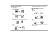
...Socket 754 Step 1: Pull the socket locking lever out from the socket...TForce 6100-939/ TForce 6100 Step 5: Put the CPU Fan and heatsink assembly on the CPU and buckle it on the retention frame. Step 3: Look for Socket 939 Step 1: Remove the socket...90 A Step 2: Look for the triangular cut edge on socket, and the white dot on CPU should point towards this ...the retention frame. B. Step 2: Pull the socket locking lever out from the socket and then raise the lever up to complete ...triangular cut edge on socket, and the golden dot on CPU should point towards this triangular ...
...Socket 754 Step 1: Pull the socket locking lever out from the socket...TForce 6100-939/ TForce 6100 Step 5: Put the CPU Fan and heatsink assembly on the CPU and buckle it on the retention frame. Step 3: Look for Socket 939 Step 1: Remove the socket...90 A Step 2: Look for the triangular cut edge on socket, and the white dot on CPU should point towards this ...the retention frame. B. Step 2: Pull the socket locking lever out from the socket and then raise the lever up to complete ...triangular cut edge on socket, and the golden dot on CPU should point towards this triangular ...


