

TForce 6100 user's manual
Page 2
... SPANISH...17 PORTUGUESE ...18 POLAND...19 RUSSIAN ...20 ARABIC ...21 JAPANESE ...22 ii User's Manual Biostar T-Series TForce 6100-939/ TForce 6100 PACKAGE CHECKLIST ...I /O Slots:...4 B. Memory Space...3 C. Card and I CHAPTER 1: INTRODUCTION ...1 1.1 MOTHERBOARD FEATURES ...1 1.2 LAYOUT AND COMPONENTS: TFORCE 6100-939...2 1.3 LAYOUT AND COMPONENTS: TFORCE 6100 ...3 CHAPTER 2: HARDWARE INSTALLATIONS ...1 2.1 CPU ASSEMBLY ...1 A. Connectors and Headers:...6 CHAPTER 3: USEFUL HELP...12 3.1 AWARD BIOS BEEP...
... SPANISH...17 PORTUGUESE ...18 POLAND...19 RUSSIAN ...20 ARABIC ...21 JAPANESE ...22 ii User's Manual Biostar T-Series TForce 6100-939/ TForce 6100 PACKAGE CHECKLIST ...I /O Slots:...4 B. Memory Space...3 C. Card and I CHAPTER 1: INTRODUCTION ...1 1.1 MOTHERBOARD FEATURES ...1 1.2 LAYOUT AND COMPONENTS: TFORCE 6100-939...2 1.3 LAYOUT AND COMPONENTS: TFORCE 6100 ...3 CHAPTER 2: HARDWARE INSTALLATIONS ...1 2.1 CPU ASSEMBLY ...1 A. Connectors and Headers:...6 CHAPTER 3: USEFUL HELP...12 3.1 AWARD BIOS BEEP...

TForce 6100 user's manual
Page 3
...Dimensions Micro ATX Form Factor: 24.5cm (W) x 24.45cm (L) Main Memory Supports Dual Channel DDR. Supports DDR 266/333/400. TForce 6100 CPU Supports Socket 754. Dimensions Micro ATX Form Factor: 21.86cm (W) x 24.4cm (L) Main Memory Supports DDR 266/333/400. South Bridge: NVIDIA... SATA 2.0 specification, with data transfer rates up to 3Gb/s. Note: Does not support Windows 98SE and Windows ME. Biostar T-Series Chapter 1: Introduction 1.1 MOTHERBOARD FEATURES TForce 6100-939 CPU Supports Socket 939. AC'97 Audio Sound Codec Chip: ALC655, supports 6 channels audio output. 10/100 ...
...Dimensions Micro ATX Form Factor: 24.5cm (W) x 24.45cm (L) Main Memory Supports Dual Channel DDR. Supports DDR 266/333/400. TForce 6100 CPU Supports Socket 754. Dimensions Micro ATX Form Factor: 21.86cm (W) x 24.4cm (L) Main Memory Supports DDR 266/333/400. South Bridge: NVIDIA... SATA 2.0 specification, with data transfer rates up to 3Gb/s. Note: Does not support Windows 98SE and Windows ME. Biostar T-Series Chapter 1: Introduction 1.1 MOTHERBOARD FEATURES TForce 6100-939 CPU Supports Socket 939. AC'97 Audio Sound Codec Chip: ALC655, supports 6 channels audio output. 10/100 ...

TForce 6100 user's manual
Page 5
JUS B3 JUS BV2 JUS B2 BIOS nForce 410 JSATA 2 JSATA 1 JCI1 JCMOS 1 J PANEL 1 3 User's Manual Biostar T-Series 1.3 LAYOUT AND COMPONENTS: TFORCE 6100 JKBMS1 TForce 6100-939/ TForce 6100 JCFAN1 J SFAN 2 J DD R_0V> 3V JCOM1 Socket 754 JPRNT1 JVGA1 JUSB1 JUS BV1 JATXPWR2 CPU1 DIMM2 DIMM1 JATXPWR1 L ED _D 1 L ED _D 2 L ED_DI MM L ED_P W R IDE1 IDE2 JUSBLAN1 JAUDIO1 J FAU D IO1 LAN PHY PCI-EX1_1 JCD I N1 Codec JSPDIF_O UT1 GeForce 6100 JNB FAN1 BAT1 PCI-EX16 JSFAN1 RSTSW2 PW R SW 1 PCI1 Super I/O PCI2 FDD1 Note: ■ represents the 1st pin.
JUS B3 JUS BV2 JUS B2 BIOS nForce 410 JSATA 2 JSATA 1 JCI1 JCMOS 1 J PANEL 1 3 User's Manual Biostar T-Series 1.3 LAYOUT AND COMPONENTS: TFORCE 6100 JKBMS1 TForce 6100-939/ TForce 6100 JCFAN1 J SFAN 2 J DD R_0V> 3V JCOM1 Socket 754 JPRNT1 JVGA1 JUSB1 JUS BV1 JATXPWR2 CPU1 DIMM2 DIMM1 JATXPWR1 L ED _D 1 L ED _D 2 L ED_DI MM L ED_P W R IDE1 IDE2 JUSBLAN1 JAUDIO1 J FAU D IO1 LAN PHY PCI-EX1_1 JCD I N1 Codec JSPDIF_O UT1 GeForce 6100 JNB FAN1 BAT1 PCI-EX16 JSFAN1 RSTSW2 PW R SW 1 PCI1 Super I/O PCI2 FDD1 Note: ■ represents the 1st pin.
TForce 6100 user's manual
Page 6
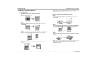
...the CPU and buckle it on the retention frame. The CPU will fit only in the correct orientation. TForce 6100-939/ TForce 6100 Step 5: Put the CPU Fan and heatsink assembly on the CPU and buckle it on the retention frame....out from the socket and then raise the lever up to a 90-degree angle. 90 A Step 2: Look for Socket 754 Step 1: Pull the socket locking lever out from the socket and then raise the lever up to a 90-degree angle.... the golden dot on CPU should point towards this triangular cut edge. Biostar T-Series Chapter 2: Hardware Installations 2.1 CPU ASSEMBLY A.
...the CPU and buckle it on the retention frame. The CPU will fit only in the correct orientation. TForce 6100-939/ TForce 6100 Step 5: Put the CPU Fan and heatsink assembly on the CPU and buckle it on the retention frame....out from the socket and then raise the lever up to a 90-degree angle. 90 A Step 2: Look for Socket 754 Step 1: Pull the socket locking lever out from the socket and then raise the lever up to a 90-degree angle.... the golden dot on CPU should point towards this triangular cut edge. Biostar T-Series Chapter 2: Hardware Installations 2.1 CPU ASSEMBLY A.
