

TForce 6100 user's manual
Page 1
... generates, uses and can radiate radio frequency energy and, if not installed and used in a particular installation. Biostar T-Series TForce 6100-939/ TForce 6100 FCC Information and Copyright This equipment has been tested and found in this user's manual is not allowed without obligation to provide reasonable protection against harmful interference in writing. All the brand...
... generates, uses and can radiate radio frequency energy and, if not installed and used in a particular installation. Biostar T-Series TForce 6100-939/ TForce 6100 FCC Information and Copyright This equipment has been tested and found in this user's manual is not allowed without obligation to provide reasonable protection against harmful interference in writing. All the brand...

TForce 6100 user's manual
Page 2
... Installation Notice...3 D. Card and I CHAPTER 1: INTRODUCTION ...1 1.1 MOTHERBOARD FEATURES ...1 1.2 LAYOUT AND COMPONENTS: TFORCE 6100-939...2 1.3 LAYOUT AND COMPONENTS: TFORCE 6100 ...3 CHAPTER 2: HARDWARE INSTALLATIONS ...1 2.1 CPU ASSEMBLY ...1 A. Central Processing Unit (CPU) for Socket 754...1...RUSSIAN ...20 ARABIC ...21 JAPANESE ...22 ii User's Manual Know your CPU version ...3 2.3 PERIPHERALS ...4 A. Biostar T-Series TForce 6100-939/ TForce 6100 PACKAGE CHECKLIST ...I /O Slots:...4 B. Central Processing Unit (CPU) for Socket 939...1 B. Memory Space...3 C....
... Installation Notice...3 D. Card and I CHAPTER 1: INTRODUCTION ...1 1.1 MOTHERBOARD FEATURES ...1 1.2 LAYOUT AND COMPONENTS: TFORCE 6100-939...2 1.3 LAYOUT AND COMPONENTS: TFORCE 6100 ...3 CHAPTER 2: HARDWARE INSTALLATIONS ...1 2.1 CPU ASSEMBLY ...1 A. Central Processing Unit (CPU) for Socket 754...1...RUSSIAN ...20 ARABIC ...21 JAPANESE ...22 ii User's Manual Know your CPU version ...3 2.3 PERIPHERALS ...4 A. Biostar T-Series TForce 6100-939/ TForce 6100 PACKAGE CHECKLIST ...I /O Slots:...4 B. Central Processing Unit (CPU) for Socket 939...1 B. Memory Space...3 C....

TForce 6100 user's manual
Page 3
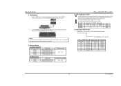
... Vertical audio port including 1 Line-in connector, 1 Line-out connector, and 1 MIC-in connector. One CD-ROM audio-in connector. 1 User's Manual South Bridge: NVIDIA nForce 410. Operating Systems Supports Windows 2000 and Windows XP. Supports HyperTransport Technology up to 1600MT/s. Serial ATA nForce 410 supports SATA... "Smart Guardian" function IDE 2 on-board connectors support 4 IDE disk drives. Back Panel I /O Chip: ITE IT8712F. Supports AMD Sempron processor. Biostar T-Series Chapter 1: Introduction 1.1 MOTHERBOARD FEATURES TForce 6100-939 CPU Supports Socket 939.
... Vertical audio port including 1 Line-in connector, 1 Line-out connector, and 1 MIC-in connector. One CD-ROM audio-in connector. 1 User's Manual South Bridge: NVIDIA nForce 410. Operating Systems Supports Windows 2000 and Windows XP. Supports HyperTransport Technology up to 1600MT/s. Serial ATA nForce 410 supports SATA... "Smart Guardian" function IDE 2 on-board connectors support 4 IDE disk drives. Back Panel I /O Chip: ITE IT8712F. Supports AMD Sempron processor. Biostar T-Series Chapter 1: Introduction 1.1 MOTHERBOARD FEATURES TForce 6100-939 CPU Supports Socket 939.

TForce 6100 user's manual
Page 4
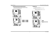
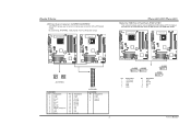
Biostar T-Series 1.2 LAYOUT AND COMPONENTS: TFORCE 6100-939 JKBMS1 JKBV1 J CFAN 1 CPU1 TForce 6100-939/ TForce 6100 J DDR _0V> 3V JCOM1 Socket 939 JPRNT1 DIMMB1 DIMMB2 DIMMA1 DIMMA2 JVGA1 JUSB1 JUS BV1 JATXPWR2 JUSBLAN1 JAUDIO1 JAUDIO2 LAN PHY JNFAN1 J CD IN1 PCI-EX1_1 GeForce 6100 BAT1 Codec JSPDIF_O UT1 PCI-EX16 PCI1 J US BV2 JUS B2 JUSB3 Super I/O PCI2...
Biostar T-Series 1.2 LAYOUT AND COMPONENTS: TFORCE 6100-939 JKBMS1 JKBV1 J CFAN 1 CPU1 TForce 6100-939/ TForce 6100 J DDR _0V> 3V JCOM1 Socket 939 JPRNT1 DIMMB1 DIMMB2 DIMMA1 DIMMA2 JVGA1 JUSB1 JUS BV1 JATXPWR2 JUSBLAN1 JAUDIO1 JAUDIO2 LAN PHY JNFAN1 J CD IN1 PCI-EX1_1 GeForce 6100 BAT1 Codec JSPDIF_O UT1 PCI-EX16 PCI1 J US BV2 JUS B2 JUSB3 Super I/O PCI2...

TForce 6100 user's manual
Page 5
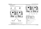
Biostar T-Series 1.3 LAYOUT AND COMPONENTS: TFORCE 6100 JKBMS1 TForce 6100-939/ TForce 6100 JCFAN1 J SFAN 2 J DD R_0V> 3V JCOM1 Socket 754 JPRNT1 JVGA1 JUSB1 JUS BV1 JATXPWR2 CPU1 DIMM2 DIMM1 JATXPWR1 L ED _D 1 L ED _D 2 L ED_DI MM L ED_P W R IDE1 IDE2 JUSBLAN1 JAUDIO1 J FAU D IO1 LAN PHY PCI-EX1_1 JCD I N1 Codec JSPDIF_O UT1 GeForce 6100 JNB FAN1 BAT1 PCI-EX16 JSFAN1 RSTSW2 PW R SW 1 PCI1 Super I/O PCI2 FDD1 Note: ■ represents the 1st pin. JUS B3 JUS BV2 JUS B2 BIOS nForce 410 JSATA 2 JSATA 1 JCI1 JCMOS 1 J PANEL 1 3 User's Manual
Biostar T-Series 1.3 LAYOUT AND COMPONENTS: TFORCE 6100 JKBMS1 TForce 6100-939/ TForce 6100 JCFAN1 J SFAN 2 J DD R_0V> 3V JCOM1 Socket 754 JPRNT1 JVGA1 JUSB1 JUS BV1 JATXPWR2 CPU1 DIMM2 DIMM1 JATXPWR1 L ED _D 1 L ED _D 2 L ED_DI MM L ED_P W R IDE1 IDE2 JUSBLAN1 JAUDIO1 J FAU D IO1 LAN PHY PCI-EX1_1 JCD I N1 Codec JSPDIF_O UT1 GeForce 6100 JNB FAN1 BAT1 PCI-EX16 JSFAN1 RSTSW2 PW R SW 1 PCI1 Super I/O PCI2 FDD1 Note: ■ represents the 1st pin. JUS B3 JUS BV2 JUS B2 BIOS nForce 410 JSATA 2 JSATA 1 JCI1 JCMOS 1 J PANEL 1 3 User's Manual
TForce 6100 user's manual
Page 6
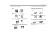
...socket locking lever out from the socket and then raise the lever up to complete the installation. TForce 6100-939/ TForce 6100 Step 5: Put the CPU Fan and heatsink assembly on the CPU and buckle it on CPU should... installation. Central Processing Unit (CPU) for the triangular cut edge. This completes the installation. 1 User's Manual The CPU will fit only in the correct orientation. Connect the CPU FAN power cable into the JCFAN1. This...3: Look for Socket 939 Step 1: Remove the socket protection cap. Biostar T-Series Chapter 2: Hardware Installations 2.1 CPU ASSEMBLY A.
...socket locking lever out from the socket and then raise the lever up to complete the installation. TForce 6100-939/ TForce 6100 Step 5: Put the CPU Fan and heatsink assembly on the CPU and buckle it on CPU should... installation. Central Processing Unit (CPU) for the triangular cut edge. This completes the installation. 1 User's Manual The CPU will fit only in the correct orientation. Connect the CPU FAN power cable into the JCFAN1. This...3: Look for Socket 939 Step 1: Remove the socket protection cap. Biostar T-Series Chapter 2: Hardware Installations 2.1 CPU ASSEMBLY A.

TForce 6100 user's manual
Page 7
Biostar T-Series C. About FAN Headers TForce 6100-939 CPU Fan Power Header: JCFAN1 System Fan Power Headers: JSFAN1/JSFAN2 North Bridge Fan Power Header: JNFAN1 JCFAN1 31 JNFAN1 3 Pin Assignment 1 1 Ground 2 +12V 3 FAN RPM rate sense JSFAN1 (Does not support JSFAN2.) 13 JSFAN2 3 1 TForce 6100 CPU...#2, and the black wire is Ground and should be connected to GND. 2.2 SYSTEM MEMORY TForce 6100-939 2 DIMMB2 DIMMB1 DIMMA2 DIMMA1 DIMMB2 DIMMB1 TForce 6100-939/ TForce 6100 TForce 6100 User's Manual When connecting with Smart Fan Control utilities. It supports 3 pin head connector.
Biostar T-Series C. About FAN Headers TForce 6100-939 CPU Fan Power Header: JCFAN1 System Fan Power Headers: JSFAN1/JSFAN2 North Bridge Fan Power Header: JNFAN1 JCFAN1 31 JNFAN1 3 Pin Assignment 1 1 Ground 2 +12V 3 FAN RPM rate sense JSFAN1 (Does not support JSFAN2.) 13 JSFAN2 3 1 TForce 6100 CPU...#2, and the black wire is Ground and should be connected to GND. 2.2 SYSTEM MEMORY TForce 6100-939 2 DIMMB2 DIMMB1 DIMMA2 DIMMA1 DIMMB2 DIMMB1 TForce 6100-939/ TForce 6100 TForce 6100 User's Manual When connecting with Smart Fan Control utilities. It supports 3 pin head connector.
TForce 6100 user's manual
Page 8
... Rev CG Rev D0 Part Definition BN BP BO BY BW Revision Rev E4 Rev E3 Rev E3 Rev E6 Rev E6 3 User's Manual Total Memory Size (MB) Max is properly seated. "DS" represents Double Side DDR memory module. Notes: To remove the DDR modules,.../256MB/512MB/1GB *1 128MB/256MB/512MB/1GB *1 For TForce 6100 DIMM Socket Location DIMM1 DIMM2 DDR Module 128MB/256MB/512MB/1GB *1 128MB/256MB/512MB/1GB *1 Total Memory Size Max is 4 GB. TForce 6100-939/ TForce 6100 C. B. Star sign "*" represents leave the DIMM socket empty. Biostar T-Series A. DDR Modules 1. E, please follow the table...
... Rev CG Rev D0 Part Definition BN BP BO BY BW Revision Rev E4 Rev E3 Rev E3 Rev E6 Rev E6 3 User's Manual Total Memory Size (MB) Max is properly seated. "DS" represents Double Side DDR memory module. Notes: To remove the DDR modules,.../256MB/512MB/1GB *1 128MB/256MB/512MB/1GB *1 For TForce 6100 DIMM Socket Location DIMM1 DIMM2 DDR Module 128MB/256MB/512MB/1GB *1 128MB/256MB/512MB/1GB *1 Total Memory Size Max is 4 GB. TForce 6100-939/ TForce 6100 C. B. Star sign "*" represents leave the DIMM socket empty. Biostar T-Series A. DDR Modules 1. E, please follow the table...

TForce 6100 user's manual
Page 9
... can connect up to IDE1. The first hard drive should always be connected to four hard disk drives. TForce 6100-939 TForce 6100 FDD1 33 1 34 2 2 34 1 33 TForce 6100 IDE1 40 39 2 1 IDE2 4 User's Manual TForce 6100-939 TForce 6100-939/ TForce 6100 Hard Disk Connectors: IDE1/IDE2 The motherboard has two 32-bit Enhanced PCI IDE Controllers that supports 360K, 720K...
... can connect up to IDE1. The first hard drive should always be connected to four hard disk drives. TForce 6100-939 TForce 6100 FDD1 33 1 34 2 2 34 1 33 TForce 6100 IDE1 40 39 2 1 IDE2 4 User's Manual TForce 6100-939 TForce 6100-939/ TForce 6100 Hard Disk Connectors: IDE1/IDE2 The motherboard has two 32-bit Enhanced PCI IDE Controllers that supports 360K, 720K...
TForce 6100 user's manual
Page 10
... is up to 4GB/s per direction. Maximum bandwidth is designated as 32 bits. PCI Express 1.0a compliant. - PCI Express 1.0a compliant. - TForce 6100-939 TForce 6100 PCI1 PCI2 TForce 6100 PCI-EX1_1 PCI-EX16 5 User's Manual Biostar T-Series Peripheral Component Interconnect Slots: PCI1~PCI2 This motherboard is a bus standard for Peripheral Component Interconnect, and it is equipped with...
... is up to 4GB/s per direction. Maximum bandwidth is designated as 32 bits. PCI Express 1.0a compliant. - PCI Express 1.0a compliant. - TForce 6100-939 TForce 6100 PCI1 PCI2 TForce 6100 PCI-EX1_1 PCI-EX16 5 User's Manual Biostar T-Series Peripheral Component Interconnect Slots: PCI1~PCI2 This motherboard is a bus standard for Peripheral Component Interconnect, and it is equipped with...
TForce 6100 user's manual
Page 11
TForce 6100-939 TForce 6100 Pin opened Pin closed Pin1-2 closed . When "JDDR_OV>3V" jumper cap is placed on Pin 1-2, memory voltage will be fixed at 3.3V automatically, and can be adjusted under CMOS setup. 2. User's Manual The default setting is an on Pin 2-3, memory voltage can 't be manually...supports up jumpers. TForce 6100-939/ TForce 6100 LED Indicators and Buttons There are 4 LED indicators on -board Reset button. TForce 6100-939 TForce 6100 JDDR_OV>3V 13 13 31 31 13 31 Pin 1-2 Close Pin 2-3 Close (Default) Note: 1. Biostar T-Series B. ...
TForce 6100-939 TForce 6100 Pin opened Pin closed Pin1-2 closed . When "JDDR_OV>3V" jumper cap is placed on Pin 1-2, memory voltage will be fixed at 3.3V automatically, and can be adjusted under CMOS setup. 2. User's Manual The default setting is an on Pin 2-3, memory voltage can 't be manually...supports up jumpers. TForce 6100-939/ TForce 6100 LED Indicators and Buttons There are 4 LED indicators on -board Reset button. TForce 6100-939 TForce 6100 JDDR_OV>3V 13 13 31 31 13 31 Pin 1-2 Close Pin 2-3 Close (Default) Note: 1. Biostar T-Series B. ...
TForce 6100 user's manual
Page 12
... also can be connected with internal USB devices, like USB card reader. TForce 6100-939 TForce 6100 TForce 6100-939/ TForce 6100 Headers for USB Ports at Front Panel: JUSB2~JUSB3 This connector allows user to CPU power circuit. TForce 6100-939 TForce 6100 11 24 4 3 1 4 1 2 2 3 JATXPWR2 JATXPWR1: Pin...- 4 USB- 5 USB+ JUSB3 10 9 Pin Assignment 6 USB+ 7 Ground 8 Ground 9 Key 10 NC JUSB3 2 1 JUSB2 10 9 User's Manual Biostar T-Series ATX Power Source Connectors: JATXPWR1/JATXPWR2 JATXPWR1 allows user to connect 24-pin power connector on the ATX power supply.
... also can be connected with internal USB devices, like USB card reader. TForce 6100-939 TForce 6100 TForce 6100-939/ TForce 6100 Headers for USB Ports at Front Panel: JUSB2~JUSB3 This connector allows user to CPU power circuit. TForce 6100-939 TForce 6100 11 24 4 3 1 4 1 2 2 3 JATXPWR2 JATXPWR1: Pin...- 4 USB- 5 USB+ JUSB3 10 9 Pin Assignment 6 USB+ 7 Ground 8 Ground 9 Key 10 NC JUSB3 2 1 JUSB2 10 9 User's Manual Biostar T-Series ATX Power Source Connectors: JATXPWR1/JATXPWR2 JATXPWR1 allows user to connect 24-pin power connector on the ATX power supply.

TForce 6100 user's manual
Page 13
TForce 6100-939 TForce 6100 TForce 6100-939/ TForce 6100 JPANEL1: Header for front USB headers (JUSB2/JUSB3). It allows user to support this function "Power...IrDA Connection. Biostar T-Series Power Source Headers for USB Ports: JUSBV1/JUSBV2 Pin 1-2 Close: JUSBV1: +5V for USB ports at JUSB1 and JUSBLAN1 are powered with +5V standby voltage. JUSBV2: Front USB headers (JUSB2/JUSB3) are powered with +5V standby voltage. TForce 6100-939 TForce 6100 JUSBV1 1 3...JUSBV2: +5V for Front Panel Facilities This 24-pin connector includes Power-on button IrDA Connector User's Manual
TForce 6100-939 TForce 6100 TForce 6100-939/ TForce 6100 JPANEL1: Header for front USB headers (JUSB2/JUSB3). It allows user to support this function "Power...IrDA Connection. Biostar T-Series Power Source Headers for USB Ports: JUSBV1/JUSBV2 Pin 1-2 Close: JUSBV1: +5V for USB ports at JUSB1 and JUSBLAN1 are powered with +5V standby voltage. JUSBV2: Front USB headers (JUSB2/JUSB3) are powered with +5V standby voltage. TForce 6100-939 TForce 6100 JUSBV1 1 3...JUSBV2: +5V for Front Panel Facilities This 24-pin connector includes Power-on button IrDA Connector User's Manual

TForce 6100 user's manual
Page 14
TForce 6100-939 TForce 6100 JAUDIO2 1 JFAUDIO1 2 13 Pin Assignment 1 MIC-in/ Stereo MIC-in R 2 Ground 3 Stereo MIC-in L 4 Audio power 5 Right line-out/ Speaker-out Right 6 Right.... Biostar T-Series Front Panel Audio-out Header: JAUDIO2/JFAUDIO1 This connector will disable the output on the PC case. TForce 6100-939 TForce 6100 TForce 6100-939/ TForce 6100 Serial ATA Connectors: JSATA1~JSATA2 The motherboard has an SATA Controller in (optional) JSATA1 JSATA2 1 47 Pin Assignment 1 Ground 2 TX+ 3 TX- 4 Ground 5 RX- 6 RX+ 7 Ground 9 User's Manual It...
TForce 6100-939 TForce 6100 JAUDIO2 1 JFAUDIO1 2 13 Pin Assignment 1 MIC-in/ Stereo MIC-in R 2 Ground 3 Stereo MIC-in L 4 Audio power 5 Right line-out/ Speaker-out Right 6 Right.... Biostar T-Series Front Panel Audio-out Header: JAUDIO2/JFAUDIO1 This connector will disable the output on the PC case. TForce 6100-939 TForce 6100 TForce 6100-939/ TForce 6100 Serial ATA Connectors: JSATA1~JSATA2 The motherboard has an SATA Controller in (optional) JSATA1 JSATA2 1 47 Pin Assignment 1 Ground 2 TX+ 3 TX- 4 Ground 5 RX- 6 RX+ 7 Ground 9 User's Manual It...

TForce 6100 user's manual
Page 15
... User's Manual Reset your desired password or clear the CMOS data. Biostar T-Series Clear CMOS Header: JCMOS1 By placing the jumper on pin 2-3, it allows user to restore the BIOS safe setting and the CMOS data, please carefully follow the procedures to "Pin 1-2 Close". 5. Wait for PS/2 keyboard and mouse.. TForce 6100-939/ TForce 6100 Power...
... User's Manual Reset your desired password or clear the CMOS data. Biostar T-Series Clear CMOS Header: JCMOS1 By placing the jumper on pin 2-3, it allows user to restore the BIOS safe setting and the CMOS data, please carefully follow the procedures to "Pin 1-2 Close". 5. Wait for PS/2 keyboard and mouse.. TForce 6100-939/ TForce 6100 Power...

TForce 6100 user's manual
Page 16
...'s Manual If the signal has been triggered, it will record to connect the audio source from a variety of devices, like CD-ROM, DVD-ROM, PCI sound card, PCI TV tuner card etc.. TForce 6100-939 TForce 6100 JCDIN1 1 4 Pin Assignment 1 Left channel input 2 Ground 3 Ground 4 Right channel input JCI1 12 Pin Assignment 1 Case open status. Biostar...
...'s Manual If the signal has been triggered, it will record to connect the audio source from a variety of devices, like CD-ROM, DVD-ROM, PCI sound card, PCI TV tuner card etc.. TForce 6100-939 TForce 6100 JCDIN1 1 4 Pin Assignment 1 Left channel input 2 Ground 3 Ground 4 Right channel input JCI1 12 Pin Assignment 1 Case open status. Biostar...

TForce 6100 user's manual
Page 17
... prompt. 8. Download the Flash Utility "AWDFLASH.exe" from Biostar website. 4. Biostar T-Series Digital Audio-out Connector: JSPDIF_OUT This connector allows users to restore the BIOS: 1. Copy "AWDFLASH.exe" and respective BIOS onto floppy disk. 5. TForce 6100-939 TForce 6100 JSPDIF_OUT 3 1 Pin Assignment 1 +5V 2 SPDIF OUT 3 Ground TForce 6100-939/ TForce 6100 CHAPTER 3: USEFUL HELP 3.1 AWARD BIOS BEEP CODE Beep Sound...
... prompt. 8. Download the Flash Utility "AWDFLASH.exe" from Biostar website. 4. Biostar T-Series Digital Audio-out Connector: JSPDIF_OUT This connector allows users to restore the BIOS: 1. Copy "AWDFLASH.exe" and respective BIOS onto floppy disk. 5. TForce 6100-939 TForce 6100 JSPDIF_OUT 3 1 Pin Assignment 1 +5V 2 SPDIF OUT 3 Ground TForce 6100-939/ TForce 6100 CHAPTER 3: USEFUL HELP 3.1 AWARD BIOS BEEP CODE Beep Sound...

TForce 6100 user's manual
Page 18
...setup. Wait for a few seconds that means the CPU protection function has been activated. TForce 6100-939/ TForce 6100 3.3 TROUBLESHOOTING Problem Solution 1. Indicator light on keyboard does not turn on. 3. System... for a few seconds. 3. Wait for a few seconds. 2. Reformat the hard drive. Biostar T-Series B. CPU Overheated If the system shuts down automatically after installing second hard drive. 1.... When the CPU is placed evenly with other drives. 13 User's Manual CPU fan is securely Power light don't illuminate, fan plugged in the power ...
...setup. Wait for a few seconds that means the CPU protection function has been activated. TForce 6100-939/ TForce 6100 3.3 TROUBLESHOOTING Problem Solution 1. Indicator light on keyboard does not turn on. 3. System... for a few seconds. 3. Wait for a few seconds. 2. Reformat the hard drive. Biostar T-Series B. CPU Overheated If the system shuts down automatically after installing second hard drive. 1.... When the CPU is placed evenly with other drives. 13 User's Manual CPU fan is securely Power light don't illuminate, fan plugged in the power ...

