

TForce 6100 user's manual
Page 1
... Guide x 1 Serial ATA Cable x 2 Fully Setup Driver CD x 1 Rear I/O Panel for any purpose. Further the vendor reserves the right to revise this user's manual. Biostar T-Series TForce 6100-939/ TForce 6100 FCC Information and Copyright This equipment has been tested and found in a particular installation. There is not allowed without obligation to notify any party beforehand...
... Guide x 1 Serial ATA Cable x 2 Fully Setup Driver CD x 1 Rear I/O Panel for any purpose. Further the vendor reserves the right to revise this user's manual. Biostar T-Series TForce 6100-939/ TForce 6100 FCC Information and Copyright This equipment has been tested and found in a particular installation. There is not allowed without obligation to notify any party beforehand...

TForce 6100 user's manual
Page 2
... Overheated...13 3.3 TROUBLESHOOTING ...13 GERMAN...14 FRENCH ...15 ITALIAN ...16 SPANISH...17 PORTUGUESE ...18 POLAND...19 RUSSIAN ...20 ARABIC ...21 JAPANESE ...22 ii User's Manual Biostar T-Series TForce 6100-939/ TForce 6100 PACKAGE CHECKLIST ...I /O Slots:...4 B. Connectors and Headers:...6 CHAPTER 3: USEFUL HELP...12 3.1 AWARD BIOS BEEP CODE...12 3.2 EXTRA INFORMATION ...12 A. About FAN Headers ...2 2.2 SYSTEM MEMORY...2 A. Memory...
... Overheated...13 3.3 TROUBLESHOOTING ...13 GERMAN...14 FRENCH ...15 ITALIAN ...16 SPANISH...17 PORTUGUESE ...18 POLAND...19 RUSSIAN ...20 ARABIC ...21 JAPANESE ...22 ii User's Manual Biostar T-Series TForce 6100-939/ TForce 6100 PACKAGE CHECKLIST ...I /O Slots:...4 B. Connectors and Headers:...6 CHAPTER 3: USEFUL HELP...12 3.1 AWARD BIOS BEEP CODE...12 3.2 EXTRA INFORMATION ...12 A. About FAN Headers ...2 2.2 SYSTEM MEMORY...2 A. Memory...

TForce 6100 user's manual
Page 3
....45cm (L) Main Memory Supports Dual Channel DDR. Supports DDR 266/333/400. TForce 6100-939/ TForce 6100 Chipset North Bridge: NVIDIA Geforce6100. Operating Systems Supports Windows 2000 and Windows XP. Two PCI slots. Back Panel I /O Chip: ITE IT8712F. Biostar T-Series Chapter 1: Introduction 1.1 MOTHERBOARD FEATURES TForce 6100-939 CPU Supports Socket 939. Maximum memory space is 2GB, supporting 2 DIMM...
....45cm (L) Main Memory Supports Dual Channel DDR. Supports DDR 266/333/400. TForce 6100-939/ TForce 6100 Chipset North Bridge: NVIDIA Geforce6100. Operating Systems Supports Windows 2000 and Windows XP. Two PCI slots. Back Panel I /O Chip: ITE IT8712F. Biostar T-Series Chapter 1: Introduction 1.1 MOTHERBOARD FEATURES TForce 6100-939 CPU Supports Socket 939. Maximum memory space is 2GB, supporting 2 DIMM...

TForce 6100 user's manual
Page 4
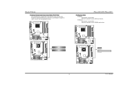
Biostar T-Series 1.2 LAYOUT AND COMPONENTS: TFORCE 6100-939 JKBMS1 JKBV1 J CFAN 1 CPU1 TForce 6100-939/ TForce 6100 J DDR _0V> 3V JCOM1 Socket 939 JPRNT1 DIMMB1 DIMMB2 DIMMA1 DIMMA2 JVGA1 JUSB1 JUS BV1 JATXPWR2 JUSBLAN1 JAUDIO1 JAUDIO2 LAN PHY JNFAN1 J CD IN1 PCI-EX1_1 GeForce 6100 BAT1 Codec JSPDIF_O UT1 PCI-EX16 PCI1 J US BV2 JUS B2 JUSB3 Super I/O PCI2 FDD1...
Biostar T-Series 1.2 LAYOUT AND COMPONENTS: TFORCE 6100-939 JKBMS1 JKBV1 J CFAN 1 CPU1 TForce 6100-939/ TForce 6100 J DDR _0V> 3V JCOM1 Socket 939 JPRNT1 DIMMB1 DIMMB2 DIMMA1 DIMMA2 JVGA1 JUSB1 JUS BV1 JATXPWR2 JUSBLAN1 JAUDIO1 JAUDIO2 LAN PHY JNFAN1 J CD IN1 PCI-EX1_1 GeForce 6100 BAT1 Codec JSPDIF_O UT1 PCI-EX16 PCI1 J US BV2 JUS B2 JUSB3 Super I/O PCI2 FDD1...

TForce 6100 user's manual
Page 5
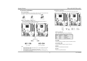
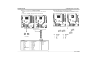
JUS B3 JUS BV2 JUS B2 BIOS nForce 410 JSATA 2 JSATA 1 JCI1 JCMOS 1 J PANEL 1 3 User's Manual Biostar T-Series 1.3 LAYOUT AND COMPONENTS: TFORCE 6100 JKBMS1 TForce 6100-939/ TForce 6100 JCFAN1 J SFAN 2 J DD R_0V> 3V JCOM1 Socket 754 JPRNT1 JVGA1 JUSB1 JUS BV1 JATXPWR2 CPU1 DIMM2 DIMM1 JATXPWR1 L ED _D 1 L ED _D 2 L ED_DI MM L ED_P W R IDE1 IDE2 JUSBLAN1 JAUDIO1 J FAU D IO1 LAN PHY PCI-EX1_1 JCD I N1 Codec JSPDIF_O UT1 GeForce 6100 JNB FAN1 BAT1 PCI-EX16 JSFAN1 RSTSW2 PW R SW 1 PCI1 Super I/O PCI2 FDD1 Note: ■ represents the 1st pin.
JUS B3 JUS BV2 JUS B2 BIOS nForce 410 JSATA 2 JSATA 1 JCI1 JCMOS 1 J PANEL 1 3 User's Manual Biostar T-Series 1.3 LAYOUT AND COMPONENTS: TFORCE 6100 JKBMS1 TForce 6100-939/ TForce 6100 JCFAN1 J SFAN 2 J DD R_0V> 3V JCOM1 Socket 754 JPRNT1 JVGA1 JUSB1 JUS BV1 JATXPWR2 CPU1 DIMM2 DIMM1 JATXPWR1 L ED _D 1 L ED _D 2 L ED_DI MM L ED_P W R IDE1 IDE2 JUSBLAN1 JAUDIO1 J FAU D IO1 LAN PHY PCI-EX1_1 JCD I N1 Codec JSPDIF_O UT1 GeForce 6100 JNB FAN1 BAT1 PCI-EX16 JSFAN1 RSTSW2 PW R SW 1 PCI1 Super I/O PCI2 FDD1 Note: ■ represents the 1st pin.
TForce 6100 user's manual
Page 6
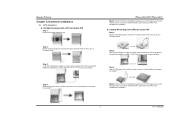
... a 90-degree angle. TForce 6100-939/ TForce 6100 Step 5: Put the CPU Fan and heatsink assembly on the CPU and buckle it on the retention frame. Central Processing Unit (CPU) for the triangular cut edge on socket, and the golden dot on CPU should point towards this triangular cut edge. Biostar T-Series Chapter 2: Hardware Installations 2.1 CPU...
... a 90-degree angle. TForce 6100-939/ TForce 6100 Step 5: Put the CPU Fan and heatsink assembly on the CPU and buckle it on the retention frame. Central Processing Unit (CPU) for the triangular cut edge on socket, and the golden dot on CPU should point towards this triangular cut edge. Biostar T-Series Chapter 2: Hardware Installations 2.1 CPU...

TForce 6100 user's manual
Page 7
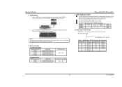
... Power Header: JNFAN1 JCFAN1 31 JNFAN1 3 Pin Assignment 1 1 Ground 2 +12V 3 FAN RPM rate sense JSFAN1 (Does not support JSFAN2.) 13 JSFAN2 3 1 TForce 6100 CPU Fan Power Header: JCFAN1 System Fan Power Headers: JSFAN1/JSFAN2 North Bridge Fan Power Header: JNBFAN1 JCFAN1 JSFAN2 31 JNBFAN1 1 3 Pin Assignment 1 Ground 2 +... positive and should be connected to pin#2, and the black wire is Ground and should be connected to GND. 2.2 SYSTEM MEMORY TForce 6100-939 2 DIMMB2 DIMMB1 DIMMA2 DIMMA1 DIMMB2 DIMMB1 TForce 6100-939/ TForce 6100 TForce 6100 User's Manual Biostar T-Series C.
... Power Header: JNFAN1 JCFAN1 31 JNFAN1 3 Pin Assignment 1 1 Ground 2 +12V 3 FAN RPM rate sense JSFAN1 (Does not support JSFAN2.) 13 JSFAN2 3 1 TForce 6100 CPU Fan Power Header: JCFAN1 System Fan Power Headers: JSFAN1/JSFAN2 North Bridge Fan Power Header: JNBFAN1 JCFAN1 JSFAN2 31 JNBFAN1 1 3 Pin Assignment 1 Ground 2 +... positive and should be connected to pin#2, and the black wire is Ground and should be connected to GND. 2.2 SYSTEM MEMORY TForce 6100-939 2 DIMMB2 DIMMB1 DIMMA2 DIMMA1 DIMMB2 DIMMB1 TForce 6100-939/ TForce 6100 TForce 6100 User's Manual Biostar T-Series C.
TForce 6100 user's manual
Page 8
Align a DIMM on the slot such that the notch on the DIMM matches the break on the slot. 2. TForce 6100-939/ TForce 6100 C. Biostar T-Series A. Unlock a DIMM slot by pressing the retaining clips outward. Insert the DIMM vertically and firmly into the slot until the ...DIMMA1 DIMMA2 DIMMB1 DIMMB2 DDR Module 128MB/256MB/512MB/1GB *1 128MB/256MB/512MB/1GB *1 128MB/256MB/512MB/1GB *1 128MB/256MB/512MB/1GB *1 For TForce 6100 DIMM Socket Location DIMM1 DIMM2 DDR Module 128MB/256MB/512MB/1GB *1 128MB/256MB/512MB/1GB *1 Total Memory Size Max is properly seated. B. DDR ...
Align a DIMM on the slot such that the notch on the DIMM matches the break on the slot. 2. TForce 6100-939/ TForce 6100 C. Biostar T-Series A. Unlock a DIMM slot by pressing the retaining clips outward. Insert the DIMM vertically and firmly into the slot until the ...DIMMA1 DIMMA2 DIMMB1 DIMMB2 DDR Module 128MB/256MB/512MB/1GB *1 128MB/256MB/512MB/1GB *1 128MB/256MB/512MB/1GB *1 128MB/256MB/512MB/1GB *1 For TForce 6100 DIMM Socket Location DIMM1 DIMM2 DDR Module 128MB/256MB/512MB/1GB *1 128MB/256MB/512MB/1GB *1 Total Memory Size Max is properly seated. B. DDR ...

TForce 6100 user's manual
Page 9
...) and IDE2 (secondary). The first hard drive should always be connected to four hard disk drives. TForce 6100-939 TForce 6100 FDD1 33 1 34 2 2 34 1 33 TForce 6100 IDE1 40 39 2 1 IDE2 4 User's Manual This connector supports the provided floppy drive ribbon cables... floppy disk connector that provide PIO Mode 0~4, Bus Master, and Ultra DMA 33/66/100/133 functionality. Biostar T-Series 2.3 PERIPHERALS A. TForce 6100-939 TForce 6100-939/ TForce 6100 Hard Disk Connectors: IDE1/IDE2 The motherboard has two 32-bit Enhanced PCI IDE Controllers that supports 360K, ...
...) and IDE2 (secondary). The first hard drive should always be connected to four hard disk drives. TForce 6100-939 TForce 6100 FDD1 33 1 34 2 2 34 1 33 TForce 6100 IDE1 40 39 2 1 IDE2 4 User's Manual This connector supports the provided floppy drive ribbon cables... floppy disk connector that provide PIO Mode 0~4, Bus Master, and Ultra DMA 33/66/100/133 functionality. Biostar T-Series 2.3 PERIPHERALS A. TForce 6100-939 TForce 6100-939/ TForce 6100 Hard Disk Connectors: IDE1/IDE2 The motherboard has two 32-bit Enhanced PCI IDE Controllers that supports 360K, ...
TForce 6100 user's manual
Page 10
... Peripheral Component Interconnect, and it is up to 250MB/s per direction. PCI stands for expansion cards. PCI Express 1.0a compliant. - TForce 6100-939 TForce 6100 PCI1 PCI2 TForce 6100 PCI-EX1_1 PCI-EX16 5 User's Manual Biostar T-Series Peripheral Component Interconnect Slots: PCI1~PCI2 This motherboard is equipped with 2 standard PCI slots. TForce 6100-939 TForce 6100-939/ TForce 6100 PCI-Express Slots PCI-EX16: -
... Peripheral Component Interconnect, and it is up to 250MB/s per direction. PCI stands for expansion cards. PCI Express 1.0a compliant. - TForce 6100-939 TForce 6100 PCI1 PCI2 TForce 6100 PCI-EX1_1 PCI-EX16 5 User's Manual Biostar T-Series Peripheral Component Interconnect Slots: PCI1~PCI2 This motherboard is equipped with 2 standard PCI slots. TForce 6100-939 TForce 6100-939/ TForce 6100 PCI-Express Slots PCI-EX16: -
TForce 6100 user's manual
Page 11
... VGA Error OFF OFF CPU / Chipset Error LED_DIMM: This LED indicates the voltage of memory is "open". RSTSW2: This is pin2-3 closed . TForce 6100-939/ TForce 6100 LED Indicators and Buttons There are 4 LED indicators on -board Reset button. The default setting is an on the motherboard to the table below for... under CMOS setup. 2. When "JDDR_OV>3V" jumper cap is placed on -board Power Switch button. When the jumper cap is placed on diagnostics. Biostar T-Series B. Connectors and Headers: How to setup Jumpers The illustration shows how to set up to pin1-2 closed .
... VGA Error OFF OFF CPU / Chipset Error LED_DIMM: This LED indicates the voltage of memory is "open". RSTSW2: This is pin2-3 closed . TForce 6100-939/ TForce 6100 LED Indicators and Buttons There are 4 LED indicators on -board Reset button. The default setting is an on the motherboard to the table below for... under CMOS setup. 2. When "JDDR_OV>3V" jumper cap is placed on -board Power Switch button. When the jumper cap is placed on diagnostics. Biostar T-Series B. Connectors and Headers: How to setup Jumpers The illustration shows how to set up to pin1-2 closed .
TForce 6100 user's manual
Page 12
Biostar T-Series ATX Power Source Connectors: JATXPWR1/JATXPWR2 JATXPWR1 allows user to connect additional USB cables at PC front panel, and also can be connected with internal USB devices, like USB card reader. TForce 6100-939 TForce 6100 TForce 6100-939/ TForce 6100 Headers for USB ...connector allows user to connect 24-pin power connector on the ATX power supply. By connecting JATXPWR2, it will provide +12V to CPU power circuit. TForce 6100-939 TForce 6100 11 24 4 3 1 4 1 2 2 3 JATXPWR2 JATXPWR1: Pin Assignment Pin Assignment 1 +3.3V 13 +3.3V 2 +3.3V 14 -12V ...
Biostar T-Series ATX Power Source Connectors: JATXPWR1/JATXPWR2 JATXPWR1 allows user to connect additional USB cables at PC front panel, and also can be connected with internal USB devices, like USB card reader. TForce 6100-939 TForce 6100 TForce 6100-939/ TForce 6100 Headers for USB ...connector allows user to connect 24-pin power connector on the ATX power supply. By connecting JATXPWR2, it will provide +12V to CPU power circuit. TForce 6100-939 TForce 6100 11 24 4 3 1 4 1 2 2 3 JATXPWR2 JATXPWR1: Pin Assignment Pin Assignment 1 +3.3V 13 +3.3V 2 +3.3V 14 -12V ...

TForce 6100 user's manual
Page 13
Pin 2-3 Close: JUSBV1: USB ports at JUSB1 and JUSBLAN1. Biostar T-Series Power Source Headers for USB Ports: JUSBV1/JUSBV2 Pin 1-2 Close: JUSBV1: +5V for USB ports at JUSB1 and JUSBLAN1 are powered with +5V standby voltage. ... Facilities This 24-pin connector includes Power-on button IrDA Connector User's Manual JUSBV2: Front USB headers (JUSB2/JUSB3) are powered with +5V standby voltage. TForce 6100-939 TForce 6100 JUSBV1 1 3 JUSBV2 31 13 1 31 3 13 Pin 1-2 Close (Default) 1 31 3 Pin 2-3 Close 13 Note: In order to connect the PC case's front panel switch...
Pin 2-3 Close: JUSBV1: USB ports at JUSB1 and JUSBLAN1. Biostar T-Series Power Source Headers for USB Ports: JUSBV1/JUSBV2 Pin 1-2 Close: JUSBV1: +5V for USB ports at JUSB1 and JUSBLAN1 are powered with +5V standby voltage. ... Facilities This 24-pin connector includes Power-on button IrDA Connector User's Manual JUSBV2: Front USB headers (JUSB2/JUSB3) are powered with +5V standby voltage. TForce 6100-939 TForce 6100 JUSBV1 1 3 JUSBV2 31 13 1 31 3 13 Pin 1-2 Close (Default) 1 31 3 Pin 2-3 Close 13 Note: In order to connect the PC case's front panel switch...

TForce 6100 user's manual
Page 14
... Assignment 1 Ground 2 TX+ 3 TX- 4 Ground 5 RX- 6 RX+ 7 Ground 9 User's Manual Biostar T-Series Front Panel Audio-out Header: JAUDIO2/JFAUDIO1 This connector will disable the output on the PC case. It will allow user to connect with transfer rate of 3.0 Gb/s. TForce 6100-939 TForce 6100 JAUDIO2 1 JFAUDIO1 2 13 Pin Assignment 1 MIC-in/ Stereo MIC-in R 2 Ground...
... Assignment 1 Ground 2 TX+ 3 TX- 4 Ground 5 RX- 6 RX+ 7 Ground 9 User's Manual Biostar T-Series Front Panel Audio-out Header: JAUDIO2/JFAUDIO1 This connector will disable the output on the PC case. It will allow user to connect with transfer rate of 3.0 Gb/s. TForce 6100-939 TForce 6100 JAUDIO2 1 JFAUDIO1 2 13 Pin Assignment 1 MIC-in/ Stereo MIC-in R 2 Ground...

TForce 6100 user's manual
Page 15
... 1-2 Close 1 3 Pin 2-3 Close Note: In order to "Pin 2-3 Close". 3. Wait for PS/2 keyboard and mouse.. TForce 6100-939/ TForce 6100 Power Source Header for PS/2 Keyboard/Mouse: JKBV1 Pin 1-2 Close: +5V for five seconds. 4. Remove AC power line. 2. Biostar T-Series Clear CMOS Header: JCMOS1 By placing the jumper on pin 2-3, it allows user to restore the...
... 1-2 Close 1 3 Pin 2-3 Close Note: In order to "Pin 2-3 Close". 3. Wait for PS/2 keyboard and mouse.. TForce 6100-939/ TForce 6100 Power Source Header for PS/2 Keyboard/Mouse: JKBV1 Pin 1-2 Close: +5V for five seconds. 4. Remove AC power line. 2. Biostar T-Series Clear CMOS Header: JCMOS1 By placing the jumper on pin 2-3, it allows user to restore the...

TForce 6100 user's manual
Page 16
..., like CD-ROM, DVD-ROM, PCI sound card, PCI TV tuner card etc.. Biostar T-Series CD-ROM Audio-in Connector: JCDIN1 This connector allows user to the CMOS and show the message on next boot-up. TForce 6100-939 TForce 6100 TForce 6100-939/ TForce 6100 Case Open Header: JCI1 This connector allows system to monitor PC case open signal...
..., like CD-ROM, DVD-ROM, PCI sound card, PCI TV tuner card etc.. Biostar T-Series CD-ROM Audio-in Connector: JCDIN1 This connector allows user to the CMOS and show the message on next boot-up. TForce 6100-939 TForce 6100 TForce 6100-939/ TForce 6100 Case Open Header: JCI1 This connector allows system to monitor PC case open signal...

TForce 6100 user's manual
Page 17
...will update BIOS automatically and restart. 9. Download the Flash Utility "AWDFLASH.exe" from Biostar website. 4. TForce 6100-939 TForce 6100 JSPDIF_OUT 3 1 Pin Assignment 1 +5V 2 SPDIF OUT 3 Ground TForce 6100-939/ TForce 6100 CHAPTER 3: USEFUL HELP 3.1 AWARD BIOS BEEP CODE Beep Sound Meaning One long beep ... INFORMATION A. BIOS Update After you fail to update BIOS or BIOS is shown after boot-up to restore BIOS. Biostar T-Series Digital Audio-out Connector: JSPDIF_OUT This connector allows users to restore the BIOS: 1. Make a bootable floppy disk. ...
...will update BIOS automatically and restart. 9. Download the Flash Utility "AWDFLASH.exe" from Biostar website. 4. TForce 6100-939 TForce 6100 JSPDIF_OUT 3 1 Pin Assignment 1 +5V 2 SPDIF OUT 3 Ground TForce 6100-939/ TForce 6100 CHAPTER 3: USEFUL HELP 3.1 AWARD BIOS BEEP CODE Beep Sound Meaning One long beep ... INFORMATION A. BIOS Update After you fail to update BIOS or BIOS is shown after boot-up to restore BIOS. Biostar T-Series Digital Audio-out Connector: JSPDIF_OUT This connector allows users to restore the BIOS: 1. Make a bootable floppy disk. ...

TForce 6100 user's manual
Page 18
...lights are securely plugged in . Call the drive manufacturers for a few seconds that means the CPU protection function has been activated. Biostar T-Series B. Make sure power cable is rotating normally. 3. Hard disk can : 1. Re-install applications and data using backup disks....Plug in the standard CMOS setup. Run SETUP program and select correct drive types. Power on . TForce 6100-939/ TForce 6100 3.3 TROUBLESHOOTING Problem Solution 1. System does not boot from optical drive. 1. turn on the system again. Replace cable.
...lights are securely plugged in . Call the drive manufacturers for a few seconds that means the CPU protection function has been activated. Biostar T-Series B. Make sure power cable is rotating normally. 3. Hard disk can : 1. Re-install applications and data using backup disks....Plug in the standard CMOS setup. Run SETUP program and select correct drive types. Power on . TForce 6100-939/ TForce 6100 3.3 TROUBLESHOOTING Problem Solution 1. System does not boot from optical drive. 1. turn on the system again. Replace cable.
