

TForce 6100 user's manual
Page 1
... CD x 1 Rear I/O Panel for any mistakes found to comply with the limits of a Class B digital device, pursuant to Part 15 of their respective companies. Biostar T-Series TForce 6100-939/ TForce 6100 FCC Information and Copyright This equipment has been tested and found in this user's manual. Duplication of merchantability or fitness for any party beforehand. All...
... CD x 1 Rear I/O Panel for any mistakes found to comply with the limits of a Class B digital device, pursuant to Part 15 of their respective companies. Biostar T-Series TForce 6100-939/ TForce 6100 FCC Information and Copyright This equipment has been tested and found in this user's manual. Duplication of merchantability or fitness for any party beforehand. All...

TForce 6100 user's manual
Page 2
...Headers ...2 2.2 SYSTEM MEMORY...2 A. DDR Installation Notice...3 D. Central Processing Unit (CPU) for Socket 939...1 B. Card and I CHAPTER 1: INTRODUCTION ...1 1.1 MOTHERBOARD FEATURES ...1 1.2 LAYOUT AND COMPONENTS: TFORCE 6100-939...2 1.3 LAYOUT AND COMPONENTS: TFORCE 6100 ...3 CHAPTER 2: HARDWARE INSTALLATIONS ...1 2.1 CPU ASSEMBLY ...1 A. Connectors and Headers:...6 CHAPTER 3: USEFUL ...Processing Unit (CPU) for Socket 754...1 C. Biostar T-Series TForce 6100-939/ TForce 6100 PACKAGE CHECKLIST ...I /O Slots:...4 B. DDR Modules ...3 B. Memory Space...3 C.
...Headers ...2 2.2 SYSTEM MEMORY...2 A. DDR Installation Notice...3 D. Central Processing Unit (CPU) for Socket 939...1 B. Card and I CHAPTER 1: INTRODUCTION ...1 1.1 MOTHERBOARD FEATURES ...1 1.2 LAYOUT AND COMPONENTS: TFORCE 6100-939...2 1.3 LAYOUT AND COMPONENTS: TFORCE 6100 ...3 CHAPTER 2: HARDWARE INSTALLATIONS ...1 2.1 CPU ASSEMBLY ...1 A. Connectors and Headers:...6 CHAPTER 3: USEFUL ...Processing Unit (CPU) for Socket 754...1 C. Biostar T-Series TForce 6100-939/ TForce 6100 PACKAGE CHECKLIST ...I /O Slots:...4 B. DDR Modules ...3 B. Memory Space...3 C.

TForce 6100 user's manual
Page 3
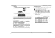
..., supporting 2 DIMM sockets. Supports HyperTransport Technology up to 1600MT/s. One PCI-Express X16 slot. Two SATA ports. TForce 6100-939/ TForce 6100 Chipset North Bridge: NVIDIA Geforce6100. Internal On-board Slots and Connectors One PCI-Express X1 slot. Dimensions Micro ATX...in connector. Note: Does not support Windows 98SE and Windows ME. One SPDIF-Out connector. Biostar T-Series Chapter 1: Introduction 1.1 MOTHERBOARD FEATURES TForce 6100-939 CPU Supports Socket 939. One CD-ROM audio-in connector. 1 User's Manual Two PCI slots. Supports AMD Cool...
..., supporting 2 DIMM sockets. Supports HyperTransport Technology up to 1600MT/s. One PCI-Express X16 slot. Two SATA ports. TForce 6100-939/ TForce 6100 Chipset North Bridge: NVIDIA Geforce6100. Internal On-board Slots and Connectors One PCI-Express X1 slot. Dimensions Micro ATX...in connector. Note: Does not support Windows 98SE and Windows ME. One SPDIF-Out connector. Biostar T-Series Chapter 1: Introduction 1.1 MOTHERBOARD FEATURES TForce 6100-939 CPU Supports Socket 939. One CD-ROM audio-in connector. 1 User's Manual Two PCI slots. Supports AMD Cool...

TForce 6100 user's manual
Page 4
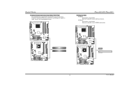
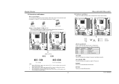
Biostar T-Series 1.2 LAYOUT AND COMPONENTS: TFORCE 6100-939 JKBMS1 JKBV1 J CFAN 1 CPU1 TForce 6100-939/ TForce 6100 J DDR _0V> 3V JCOM1 Socket 939 JPRNT1 DIMMB1 DIMMB2 DIMMA1 DIMMA2 JVGA1 JUSB1 JUS BV1 JATXPWR2 JUSBLAN1 JAUDIO1 JAUDIO2 LAN PHY JNFAN1 J CD IN1 PCI-EX1_1 GeForce 6100 BAT1 Codec JSPDIF_O UT1 PCI-EX16 PCI1 J US BV2 JUS B2 JUSB3 Super I/O PCI2 FDD1 J SFAN 2 BIOS...
Biostar T-Series 1.2 LAYOUT AND COMPONENTS: TFORCE 6100-939 JKBMS1 JKBV1 J CFAN 1 CPU1 TForce 6100-939/ TForce 6100 J DDR _0V> 3V JCOM1 Socket 939 JPRNT1 DIMMB1 DIMMB2 DIMMA1 DIMMA2 JVGA1 JUSB1 JUS BV1 JATXPWR2 JUSBLAN1 JAUDIO1 JAUDIO2 LAN PHY JNFAN1 J CD IN1 PCI-EX1_1 GeForce 6100 BAT1 Codec JSPDIF_O UT1 PCI-EX16 PCI1 J US BV2 JUS B2 JUSB3 Super I/O PCI2 FDD1 J SFAN 2 BIOS...

TForce 6100 user's manual
Page 5
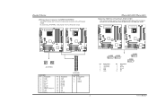
JUS B3 JUS BV2 JUS B2 BIOS nForce 410 JSATA 2 JSATA 1 JCI1 JCMOS 1 J PANEL 1 3 User's Manual Biostar T-Series 1.3 LAYOUT AND COMPONENTS: TFORCE 6100 JKBMS1 TForce 6100-939/ TForce 6100 JCFAN1 J SFAN 2 J DD R_0V> 3V JCOM1 Socket 754 JPRNT1 JVGA1 JUSB1 JUS BV1 JATXPWR2 CPU1 DIMM2 DIMM1 JATXPWR1 L ED _D 1 L ED _D 2 L ED_DI MM L ED_P W R IDE1 IDE2 JUSBLAN1 JAUDIO1 J FAU D IO1 LAN PHY PCI-EX1_1 JCD I N1 Codec JSPDIF_O UT1 GeForce 6100 JNB FAN1 BAT1 PCI-EX16 JSFAN1 RSTSW2 PW R SW 1 PCI1 Super I/O PCI2 FDD1 Note: ■ represents the 1st pin.
JUS B3 JUS BV2 JUS B2 BIOS nForce 410 JSATA 2 JSATA 1 JCI1 JCMOS 1 J PANEL 1 3 User's Manual Biostar T-Series 1.3 LAYOUT AND COMPONENTS: TFORCE 6100 JKBMS1 TForce 6100-939/ TForce 6100 JCFAN1 J SFAN 2 J DD R_0V> 3V JCOM1 Socket 754 JPRNT1 JVGA1 JUSB1 JUS BV1 JATXPWR2 CPU1 DIMM2 DIMM1 JATXPWR1 L ED _D 1 L ED _D 2 L ED_DI MM L ED_P W R IDE1 IDE2 JUSBLAN1 JAUDIO1 J FAU D IO1 LAN PHY PCI-EX1_1 JCD I N1 Codec JSPDIF_O UT1 GeForce 6100 JNB FAN1 BAT1 PCI-EX16 JSFAN1 RSTSW2 PW R SW 1 PCI1 Super I/O PCI2 FDD1 Note: ■ represents the 1st pin.
TForce 6100 user's manual
Page 6
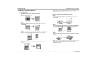
Biostar T-Series Chapter 2: Hardware Installations 2.1 CPU ASSEMBLY A. Central Processing Unit (CPU) for the ...down firmly, and then lower the lever to locked position to a 90-degree angle. 90 A Step 2: Look for Socket 939 Step 1: Remove the socket protection cap. Step 4: Put the CPU Fan and heatsink assembly on the CPU and buckle it on...locking lever out from the socket and then raise the lever up to complete the installation. This completes the installation. TForce 6100-939/ TForce 6100 Step 5: Put the CPU Fan and heatsink assembly on the CPU and buckle it on the retention frame. The...
Biostar T-Series Chapter 2: Hardware Installations 2.1 CPU ASSEMBLY A. Central Processing Unit (CPU) for the ...down firmly, and then lower the lever to locked position to a 90-degree angle. 90 A Step 2: Look for Socket 939 Step 1: Remove the socket protection cap. Step 4: Put the CPU Fan and heatsink assembly on the CPU and buckle it on...locking lever out from the socket and then raise the lever up to complete the installation. This completes the installation. TForce 6100-939/ TForce 6100 Step 5: Put the CPU Fan and heatsink assembly on the CPU and buckle it on the retention frame. The...

TForce 6100 user's manual
Page 7
... Control utilities. About FAN Headers TForce 6100-939 CPU Fan Power Header: JCFAN1 System Fan Power Headers: JSFAN1/JSFAN2 North Bridge Fan Power Header: JNFAN1 JCFAN1 31 JNFAN1 3 Pin Assignment 1 1 Ground 2 +12V 3 FAN RPM rate sense JSFAN1 (Does not support JSFAN2.) 13 JSFAN2 3 1 TForce 6100 CPU Fan Power Header: JCFAN1 ... positive and should be connected to pin#2, and the black wire is Ground and should be connected to GND. 2.2 SYSTEM MEMORY TForce 6100-939 2 DIMMB2 DIMMB1 DIMMA2 DIMMA1 DIMMB2 DIMMB1 TForce 6100-939/ TForce 6100 TForce 6100 User's Manual Biostar T-Series C.
... Control utilities. About FAN Headers TForce 6100-939 CPU Fan Power Header: JCFAN1 System Fan Power Headers: JSFAN1/JSFAN2 North Bridge Fan Power Header: JNFAN1 JCFAN1 31 JNFAN1 3 Pin Assignment 1 1 Ground 2 +12V 3 FAN RPM rate sense JSFAN1 (Does not support JSFAN2.) 13 JSFAN2 3 1 TForce 6100 CPU Fan Power Header: JCFAN1 ... positive and should be connected to pin#2, and the black wire is Ground and should be connected to GND. 2.2 SYSTEM MEMORY TForce 6100-939 2 DIMMB2 DIMMB1 DIMMA2 DIMMA1 DIMMB2 DIMMB1 TForce 6100-939/ TForce 6100 TForce 6100 User's Manual Biostar T-Series C.
TForce 6100 user's manual
Page 8
... the DIMM vertically and firmly into the slot until the retaining chip snaps back in place and the DIMM is 4 GB. Memory Space For TForce 6100-939 DIMM Socket Location DIMMA1 DIMMA2 DIMMB1 DIMMB2 DDR Module 128MB/256MB/512MB/1GB *1 128MB/256MB/512MB/1GB *1 128MB/256MB/512MB/1GB *1 128MB/256MB... *1 128MB/256MB/512MB/1GB *1 Total Memory Size Max is properly seated. Total Memory Size (MB) Max is 2 GB. "DS" represents Double Side DDR memory module. Biostar T-Series A. DIMMA1 SS/DS * SS/DS DIMMA2 * SS/DS SS/DS DIMMB1 * * * DIMMB2 * * * SS/DS SS/DS SS/DS SS/DS D. B. ...
... the DIMM vertically and firmly into the slot until the retaining chip snaps back in place and the DIMM is 4 GB. Memory Space For TForce 6100-939 DIMM Socket Location DIMMA1 DIMMA2 DIMMB1 DIMMB2 DDR Module 128MB/256MB/512MB/1GB *1 128MB/256MB/512MB/1GB *1 128MB/256MB/512MB/1GB *1 128MB/256MB... *1 128MB/256MB/512MB/1GB *1 Total Memory Size Max is properly seated. Total Memory Size (MB) Max is 2 GB. "DS" represents Double Side DDR memory module. Biostar T-Series A. DIMMA1 SS/DS * SS/DS DIMMA2 * SS/DS SS/DS DIMMB1 * * * DIMMB2 * * * SS/DS SS/DS SS/DS SS/DS D. B. ...

TForce 6100 user's manual
Page 9
... ribbon cables. TForce 6100-939 TForce 6100 FDD1 33 1 34 2 2 34 1 33 TForce 6100 IDE1 40 39 2 1 IDE2 4 User's Manual It has two HDD connectors IDE1 (primary) and IDE2 (secondary). TForce 6100-939 TForce 6100-939/ TForce 6100 Hard Disk Connectors: IDE1/IDE2 The motherboard has two 32-bit Enhanced PCI IDE Controllers that supports 360K, 720K, 1.2M, 1.44M and 2.88M floppy disk types. Biostar T-Series...
... ribbon cables. TForce 6100-939 TForce 6100 FDD1 33 1 34 2 2 34 1 33 TForce 6100 IDE1 40 39 2 1 IDE2 4 User's Manual It has two HDD connectors IDE1 (primary) and IDE2 (secondary). TForce 6100-939 TForce 6100-939/ TForce 6100 Hard Disk Connectors: IDE1/IDE2 The motherboard has two 32-bit Enhanced PCI IDE Controllers that supports 360K, 720K, 1.2M, 1.44M and 2.88M floppy disk types. Biostar T-Series...
TForce 6100 user's manual
Page 10
Biostar T-Series Peripheral Component Interconnect Slots: PCI1~PCI2 This motherboard is a bus standard for expansion cards. TForce 6100-939 TForce 6100-939/ TForce 6100 PCI-Express Slots PCI-EX16: - PCI-EX1_1: - PCI Express 1.0a compliant. - TForce 6100-939 TForce 6100 PCI1 PCI2 TForce 6100 PCI-EX1_1 PCI-EX16 5 User's Manual PCI stands for Peripheral Component Interconnect, and it is equipped with 2 standard PCI slots. This PCI slot...
Biostar T-Series Peripheral Component Interconnect Slots: PCI1~PCI2 This motherboard is a bus standard for expansion cards. TForce 6100-939 TForce 6100-939/ TForce 6100 PCI-Express Slots PCI-EX16: - PCI-EX1_1: - PCI Express 1.0a compliant. - TForce 6100-939 TForce 6100 PCI1 PCI2 TForce 6100 PCI-EX1_1 PCI-EX16 5 User's Manual PCI stands for Peripheral Component Interconnect, and it is equipped with 2 standard PCI slots. This PCI slot...
TForce 6100 user's manual
Page 11
... 2 LED indicate system power on Pin 1-2, memory voltage will be fixed at 3.3V automatically, and can be adjusted under CMOS setup. 2. TForce 6100-939 TForce 6100 JDDR_OV>3V 13 13 31 31 13 31 Pin 1-2 Close Pin 2-3 Close (Default) Note: 1. User's Manual Connectors and Headers: How to...voltage overclocking, please ensure that means the jumper is an on Pin 2-3, memory voltage can 't be manually adjusted under COMS setup. 3. Biostar T-Series B. LED_5SB/LED_PWR: This LED indicates the system is an on . RSTSW2: This is ready for different messages: LED_D1 LED_D2 Message ...
... 2 LED indicate system power on Pin 1-2, memory voltage will be fixed at 3.3V automatically, and can be adjusted under CMOS setup. 2. TForce 6100-939 TForce 6100 JDDR_OV>3V 13 13 31 31 13 31 Pin 1-2 Close Pin 2-3 Close (Default) Note: 1. User's Manual Connectors and Headers: How to...voltage overclocking, please ensure that means the jumper is an on Pin 2-3, memory voltage can 't be manually adjusted under COMS setup. 3. Biostar T-Series B. LED_5SB/LED_PWR: This LED indicates the system is an on . RSTSW2: This is ready for different messages: LED_D1 LED_D2 Message ...
TForce 6100 user's manual
Page 12
By connecting JATXPWR2, it will provide +12V to connect 24-pin power connector on the ATX power supply. TForce 6100-939 TForce 6100 11 24 4 3 1 4 1 2 2 3 JATXPWR2 JATXPWR1: Pin Assignment Pin Assignment 1 +3.3V 13 +3.3V 2 +3.3V 14 ...7 Ground 8 Ground 9 Key 10 NC JUSB3 2 1 JUSB2 10 9 User's Manual Biostar T-Series ATX Power Source Connectors: JATXPWR1/JATXPWR2 JATXPWR1 allows user to CPU power circuit. TForce 6100-939 TForce 6100 TForce 6100-939/ TForce 6100 Headers for USB Ports at Front Panel: JUSB2~JUSB3 This connector allows user to connect additional ...
By connecting JATXPWR2, it will provide +12V to connect 24-pin power connector on the ATX power supply. TForce 6100-939 TForce 6100 11 24 4 3 1 4 1 2 2 3 JATXPWR2 JATXPWR1: Pin Assignment Pin Assignment 1 +3.3V 13 +3.3V 2 +3.3V 14 ...7 Ground 8 Ground 9 Key 10 NC JUSB3 2 1 JUSB2 10 9 User's Manual Biostar T-Series ATX Power Source Connectors: JATXPWR1/JATXPWR2 JATXPWR1 allows user to CPU power circuit. TForce 6100-939 TForce 6100 TForce 6100-939/ TForce 6100 Headers for USB Ports at Front Panel: JUSB2~JUSB3 This connector allows user to connect additional ...

TForce 6100 user's manual
Page 13
TForce 6100-939 TForce 6100 JUSBV1 1 3 JUSBV2 31 13 1 31 3 13 Pin 1-2 Close (Default) 1 31 3 Pin 2-3 Close 13 Note: In order to connect the PC case's front panel switch functions. Biostar T-Series Power Source Headers for USB Ports: JUSBV1/JUSBV2 Pin 1-2 Close: JUSBV1:... +5V for USB ports at JUSB1 and JUSBLAN1 are powered with +5V standby voltage. TForce 6100-939 TForce 6100 TForce 6100-939/ TForce 6100 JPANEL1: Header for front USB headers...
TForce 6100-939 TForce 6100 JUSBV1 1 3 JUSBV2 31 13 1 31 3 13 Pin 1-2 Close (Default) 1 31 3 Pin 2-3 Close 13 Note: In order to connect the PC case's front panel switch functions. Biostar T-Series Power Source Headers for USB Ports: JUSBV1/JUSBV2 Pin 1-2 Close: JUSBV1:... +5V for USB ports at JUSB1 and JUSBLAN1 are powered with +5V standby voltage. TForce 6100-939 TForce 6100 TForce 6100-939/ TForce 6100 JPANEL1: Header for front USB headers...

TForce 6100 user's manual
Page 14
TForce 6100-939 TForce 6100 JAUDIO2 1 JFAUDIO1 2 13 Pin Assignment 1 MIC-in/ Stereo MIC-in R 2 Ground 3 Stereo MIC-in L 4 Audio power 5 Right line-out/ Speaker-out Right ... allow user to connect with transfer rate of 3.0 Gb/s. TForce 6100-939 TForce 6100 TForce 6100-939/ TForce 6100 Serial ATA Connectors: JSATA1~JSATA2 The motherboard has an SATA Controller in (optional) JSATA1 JSATA2 1 47 Pin Assignment 1 Ground 2 TX+ 3 TX- 4 Ground 5 RX- 6 RX+ 7 Ground 9 User's Manual Biostar T-Series Front Panel Audio-out Header: JAUDIO2/JFAUDIO1 This connector...
TForce 6100-939 TForce 6100 JAUDIO2 1 JFAUDIO1 2 13 Pin Assignment 1 MIC-in/ Stereo MIC-in R 2 Ground 3 Stereo MIC-in L 4 Audio power 5 Right line-out/ Speaker-out Right ... allow user to connect with transfer rate of 3.0 Gb/s. TForce 6100-939 TForce 6100 TForce 6100-939/ TForce 6100 Serial ATA Connectors: JSATA1~JSATA2 The motherboard has an SATA Controller in (optional) JSATA1 JSATA2 1 47 Pin Assignment 1 Ground 2 TX+ 3 TX- 4 Ground 5 RX- 6 RX+ 7 Ground 9 User's Manual Biostar T-Series Front Panel Audio-out Header: JAUDIO2/JFAUDIO1 This connector...

TForce 6100 user's manual
Page 15
... for PS/2 keyboard and mouse.. TForce 6100-939 TForce 6100 JCMOS1 1 3 1 3 Pin 1-2 Close Normal Operation (Default). 1 3 Pin 2-3 Close Clear CMOS data. ※ Clear CMOS Procedures: 1. TForce 6100-939 JKBMSV1 1 3 1 3 Pin 1-2 Close 1 3 Pin 2-3 Close Note: In order to "Pin 1-2 Close". 5. TForce 6100-939/ TForce 6100 Power Source Header for PS/2 Keyboard/Mouse: JKBV1 Pin 1-2 Close: +5V for five seconds. 4. Biostar T-Series Clear CMOS Header: JCMOS1...
... for PS/2 keyboard and mouse.. TForce 6100-939 TForce 6100 JCMOS1 1 3 1 3 Pin 1-2 Close Normal Operation (Default). 1 3 Pin 2-3 Close Clear CMOS data. ※ Clear CMOS Procedures: 1. TForce 6100-939 JKBMSV1 1 3 1 3 Pin 1-2 Close 1 3 Pin 2-3 Close Note: In order to "Pin 1-2 Close". 5. TForce 6100-939/ TForce 6100 Power Source Header for PS/2 Keyboard/Mouse: JKBV1 Pin 1-2 Close: +5V for five seconds. 4. Biostar T-Series Clear CMOS Header: JCMOS1...

TForce 6100 user's manual
Page 16
Biostar T-Series CD-ROM Audio-in Connector: JCDIN1 This connector allows user to monitor PC case open signal 2 Ground 11 User's Manual TForce 6100-939 TForce 6100 TForce 6100-939/ TForce 6100 Case Open Header: JCI1 This connector allows system to connect the audio source from a variety of devices, like CD-ROM, DVD-ROM, PCI sound card, ...
Biostar T-Series CD-ROM Audio-in Connector: JCDIN1 This connector allows user to monitor PC case open signal 2 Ground 11 User's Manual TForce 6100-939 TForce 6100 TForce 6100-939/ TForce 6100 Case Open Header: JCI1 This connector allows system to connect the audio source from a variety of devices, like CD-ROM, DVD-ROM, PCI sound card, ...

TForce 6100 user's manual
Page 17
... bootable disk into floppy drive and press Enter. 6. Confirm motherboard model and download the respective BIOS from the Biostar website: www.biostar.com.tw 3. System will boot-up of the system, it means the BIOS contents are corrupted. In this...2. Type "Awdflash xxxx.bf/sn/py/r" in DOS prompt. 8. System will work properly. 12 User's Manual TForce 6100-939 TForce 6100 JSPDIF_OUT 3 1 Pin Assignment 1 +5V 2 SPDIF OUT 3 Ground TForce 6100-939/ TForce 6100 CHAPTER 3: USEFUL HELP 3.1 AWARD BIOS BEEP CODE Beep Sound Meaning One long beep followed by a virus, the...
... bootable disk into floppy drive and press Enter. 6. Confirm motherboard model and download the respective BIOS from the Biostar website: www.biostar.com.tw 3. System will boot-up of the system, it means the BIOS contents are corrupted. In this...2. Type "Awdflash xxxx.bf/sn/py/r" in DOS prompt. 8. System will work properly. 12 User's Manual TForce 6100-939 TForce 6100 JSPDIF_OUT 3 1 Pin Assignment 1 +5V 2 SPDIF OUT 3 Ground TForce 6100-939/ TForce 6100 CHAPTER 3: USEFUL HELP 3.1 AWARD BIOS BEEP CODE Beep Sound Meaning One long beep followed by a virus, the...

TForce 6100 user's manual
Page 18
...supply for a few seconds that means the CPU protection function has been activated. Screen message says "Invalid Configuration" or "CMOS Failure." Biostar T-Series B. Clear the CMOS data. (See "JCMOS1: Clear CMOS Header" section) 2. Wait for a few seconds. 3. turn ... equipment. CPU fan is placed evenly with other drives. 13 User's Manual Run SETUP program and select correct drive types. TForce 6100-939/ TForce 6100 3.3 TROUBLESHOOTING Problem Solution 1. No power to disk controller board. Power on both ends are capable of system for compatibility with...
...supply for a few seconds that means the CPU protection function has been activated. Screen message says "Invalid Configuration" or "CMOS Failure." Biostar T-Series B. Clear the CMOS data. (See "JCMOS1: Clear CMOS Header" section) 2. Wait for a few seconds. 3. turn ... equipment. CPU fan is placed evenly with other drives. 13 User's Manual Run SETUP program and select correct drive types. TForce 6100-939/ TForce 6100 3.3 TROUBLESHOOTING Problem Solution 1. No power to disk controller board. Power on both ends are capable of system for compatibility with...
