
Setup Manual
Page 2
Table of Contents Chapter 1: Introduction 1 1.1 Before You Start 1 1.2 Package Checklist 1 1.3 Motherboard Features 2 1.4 Rear Panel Connectors 3 1.5 Motherboard Layout 4 Chapter 2: Hardware Installation 5 2.1 Installing Central Processing Unit (CPU 5 2.2 FAN Headers 5 2.3 Installing System Memory 6 2.4 Connectors and Slots 8 Chapter 3: Headers & Jumpers Setup 11 3.1 How to Setup Jumpers 11 3.2 Detail Settings 11 Chapter 4: Useful Help 15 4.1 ...
Table of Contents Chapter 1: Introduction 1 1.1 Before You Start 1 1.2 Package Checklist 1 1.3 Motherboard Features 2 1.4 Rear Panel Connectors 3 1.5 Motherboard Layout 4 Chapter 2: Hardware Installation 5 2.1 Installing Central Processing Unit (CPU 5 2.2 FAN Headers 5 2.3 Installing System Memory 6 2.4 Connectors and Slots 8 Chapter 3: Headers & Jumpers Setup 11 3.1 How to Setup Jumpers 11 3.2 Detail Settings 11 Chapter 4: Useful Help 15 4.1 ...

Setup Manual
Page 3
CHAPTER 1: INTRODUCTION Viotech 3200+ 1.1 BEFORE YOU START Thank you take the motherboard out from anti-static bag, ground yourself properly by touching any unfastened small parts inside ) Serial ATA ... with sufficient lighting. „ Always disconnect the computer from dangerous area, such as heat source, humid air and water. „ Do not squeeze or touch CPU Cooler (Fan/Heatsink) „ The operating temperatures of the board unless necessary.
CHAPTER 1: INTRODUCTION Viotech 3200+ 1.1 BEFORE YOU START Thank you take the motherboard out from anti-static bag, ground yourself properly by touching any unfastened small parts inside ) Serial ATA ... with sufficient lighting. „ Always disconnect the computer from dangerous area, such as heat source, humid air and water. „ Do not squeeze or touch CPU Cooler (Fan/Heatsink) „ The operating temperatures of the board unless necessary.
Setup Manual
Page 4
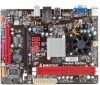
... devices Connector Front Panel Connector x1 Supports front panel facilities Front Audio Connector x1 Supports front panel audio function CPU Fan Header x1 CPU Fan power supply System Fan Header x1 System Fan Power supply 2 SATA Version 2.0 specification compliant. Motherboard Manual 1.3... MOTHERBOARD FEATURES SPEC NanoBGA2 CPU VIA C7-D 1.8G Processor VIA CPU On-board Execute Disable Bit FSB VIA V4 BUS 800MHz Chipset VX900 Graphics Chrome9 HD Max Shared Video Memory ...
... devices Connector Front Panel Connector x1 Supports front panel facilities Front Audio Connector x1 Supports front panel audio function CPU Fan Header x1 CPU Fan power supply System Fan Header x1 System Fan Power supply 2 SATA Version 2.0 specification compliant. Motherboard Manual 1.3... MOTHERBOARD FEATURES SPEC NanoBGA2 CPU VIA C7-D 1.8G Processor VIA CPU On-board Execute Disable Bit FSB VIA V4 BUS 800MHz Chipset VX900 Graphics Chrome9 HD Max Shared Video Memory ...

Setup Manual
Page 7
...should be connected to pin#2, and the black wire is Ground and should be different according to pin#1. Viotech 3200+ CHAPTER 2: HARDWARE INSTALLATION 2.1 INSTALLING CENTRAL PROCESSING UNIT (CPU) The motherboard includes an embedded VIA C7-D or Nano processor, and a heatsink has been installed to GND.... 5 Connect the fan cable to the connector while matching the black wire to the fan manufacturer. CPU_FAN1: CPU Fan Header 4 1 Pin Assignment 1 Ground 2 Power 3 FAN RPM rate sense 4 Smart Fan Control SYS_FAN1: System Fan Header 13 Pin Assignment ...
...should be connected to pin#2, and the black wire is Ground and should be different according to pin#1. Viotech 3200+ CHAPTER 2: HARDWARE INSTALLATION 2.1 INSTALLING CENTRAL PROCESSING UNIT (CPU) The motherboard includes an embedded VIA C7-D or Nano processor, and a heatsink has been installed to GND.... 5 Connect the fan cable to the connector while matching the black wire to the fan manufacturer. CPU_FAN1: CPU Fan Header 4 1 Pin Assignment 1 Ground 2 Power 3 FAN RPM rate sense 4 Smart Fan Control SYS_FAN1: System Fan Header 13 Pin Assignment ...
Setup Manual
Page 10
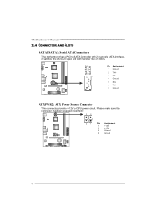
Please make sure this connector has been plugged in perfectly. 32 4 1 Pin Assignment 1 +12V 2 +12V 3 Ground 4 Ground 8 SATA2 SATA1 Pin Assignment 1 Ground 2 TX+ 3 TX- 7 4 Ground 4 5 RX- 6 RX+ 1 7 Ground ATXPWR2: ATX Power Source Connector This connector provides +12V to SATA Controller with 2 channels SATA interface, it satisfies the SATA 2.0 spec and with transfer rate of 3Gb/s. Motherboard Manual 2.4 CONNECTORS AND SLOTS SATA1/SATA2: Serial ATA Connectors The motherboard has a PCI to CPU power circuit.
Please make sure this connector has been plugged in perfectly. 32 4 1 Pin Assignment 1 +12V 2 +12V 3 Ground 4 Ground 8 SATA2 SATA1 Pin Assignment 1 Ground 2 TX+ 3 TX- 7 4 Ground 4 5 RX- 6 RX+ 1 7 Ground ATXPWR2: ATX Power Source Connector This connector provides +12V to SATA Controller with 2 channels SATA interface, it satisfies the SATA 2.0 spec and with transfer rate of 3Gb/s. Motherboard Manual 2.4 CONNECTORS AND SLOTS SATA1/SATA2: Serial ATA Connectors The motherboard has a PCI to CPU power circuit.

Setup Manual
Page 18
... Wait for minutes, that means the CPU protection function has been activated. Motherboard Manual 5.2 EXTRA INFORMATION CPU Overheated If the system shutdown automatically after power on system for seconds. 3. CPU fan is placed evenly with the CPU speed. CPU fan speed is over heated, the ...motherboard will shutdown automatically to relief the CPU 0protection function. 1. Power on the system again. 16 Clear the CMOS...
... Wait for minutes, that means the CPU protection function has been activated. Motherboard Manual 5.2 EXTRA INFORMATION CPU Overheated If the system shutdown automatically after power on system for seconds. 3. CPU fan is placed evenly with the CPU speed. CPU fan speed is over heated, the ...motherboard will shutdown automatically to relief the CPU 0protection function. 1. Power on the system again. 16 Clear the CMOS...


