
Hardware Installation Guide
Page 2
...WebEx logo are the property of Cisco and/or its peripheral devices. Catalyst 2960 Switch Hardware Installation Guide © 2005-2010 Cisco Systems, Inc. USERS MUST ...TAKE FULL RESPONSIBILITY FOR THEIR APPLICATION OF ANY PRODUCTS. Modifying the equipment without Cisco's written authorization may cause interference with Cisco's installation instructions, it off. All other countries. The use of actual IP addresses in a residential installation. All rights reserved. THE SPECIFICATIONS...
...WebEx logo are the property of Cisco and/or its peripheral devices. Catalyst 2960 Switch Hardware Installation Guide © 2005-2010 Cisco Systems, Inc. USERS MUST ...TAKE FULL RESPONSIBILITY FOR THEIR APPLICATION OF ANY PRODUCTS. Modifying the equipment without Cisco's written authorization may cause interference with Cisco's installation instructions, it off. All other countries. The use of actual IP addresses in a residential installation. All rights reserved. THE SPECIFICATIONS...

Hardware Installation Guide
Page 5
... 3-18 Troubleshooting 4-1 Diagnosing Problems 4-1 Verify Switch POST Results 4-2 Monitor Switch LEDs 4-2 Verify Switch Connections 4-2 Bad or Damaged Cable 4-2 Ethernet...Switch Performance 4-4 Speed, Duplex, and Autonegotiation 4-4 Autonegotiation and NIC Cards 4-5 Cabling Distance 4-5 Clearing the Switch IP Address and Configuration 4-5 Locating the Switch Serial Number 4-6 Technical Specifications A-1 Connector and Cable Specifications B-1 Connector Specifications B-1 10/100/1000 Ports B-1 Connecting to 1000BASE-T Devices B-2 SFP Module Ports B-3 Dual-Purpose Ports B-3 Catalyst 2960 Switch...
... 3-18 Troubleshooting 4-1 Diagnosing Problems 4-1 Verify Switch POST Results 4-2 Monitor Switch LEDs 4-2 Verify Switch Connections 4-2 Bad or Damaged Cable 4-2 Ethernet...Switch Performance 4-4 Speed, Duplex, and Autonegotiation 4-4 Autonegotiation and NIC Cards 4-5 Cabling Distance 4-5 Clearing the Switch IP Address and Configuration 4-5 Locating the Switch Serial Number 4-6 Technical Specifications A-1 Connector and Cable Specifications B-1 Connector Specifications B-1 10/100/1000 Ports B-1 Connecting to 1000BASE-T Devices B-2 SFP Module Ports B-3 Dual-Purpose Ports B-3 Catalyst 2960 Switch...

Hardware Installation Guide
Page 6
... E N D I X INDEX Console Port B-4 Cable and Adapter Specifications B-4 SFP Module Cable Specifications B-4 Two Twisted-Pair Cable Pinouts B-6 Four Twisted-Pair Cable Pinouts for 1000BASE-T Ports B-6 Crossover Cable and Adapter Pinouts B-7 Identifying a Crossover Cable B-7 Adapter Pinouts B-8 Configuring the Switch with the CLI-Based Setup Program C-1 Accessing the CLI C-1 Accessing the... Software C-3 Connecting to a Power Source C-4 Entering the Initial Configuration Information C-4 IP Settings C-5 Completing the Setup Program C-5 Catalyst 2960 Switch Hardware Installation Guide vi OL-7075-09
... E N D I X INDEX Console Port B-4 Cable and Adapter Specifications B-4 SFP Module Cable Specifications B-4 Two Twisted-Pair Cable Pinouts B-6 Four Twisted-Pair Cable Pinouts for 1000BASE-T Ports B-6 Crossover Cable and Adapter Pinouts B-7 Identifying a Crossover Cable B-7 Adapter Pinouts B-8 Configuring the Switch with the CLI-Based Setup Program C-1 Accessing the CLI C-1 Accessing the... Software C-3 Connecting to a Power Source C-4 Entering the Initial Configuration Information C-4 IP Settings C-5 Completing the Setup Program C-5 Catalyst 2960 Switch Hardware Installation Guide vi OL-7075-09

Hardware Installation Guide
Page 13
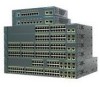
... Catalyst 2960 switches have an RPS connector: • Catalyst 2960-8TC-L • Catalyst 2960G-8TC-L • Catalyst 2960-8TC-S • Catalyst 2960PD-8TT-L • Catalyst 2960-24-S • Catalyst 2960-24TC-S • Catalyst 2960-48TT-S • Catalyst 2960-48TC-S OL-7075-09 Catalyst 2960 Switch Hardware Installation Guide 1-3 For specific information about switch support for an optional Cisco RPS 2300 or Cisco RPS 675 redundant power system that operates on specific switches...
... Catalyst 2960 switches have an RPS connector: • Catalyst 2960-8TC-L • Catalyst 2960G-8TC-L • Catalyst 2960-8TC-S • Catalyst 2960PD-8TT-L • Catalyst 2960-24-S • Catalyst 2960-24TC-S • Catalyst 2960-48TT-S • Catalyst 2960-48TC-S OL-7075-09 Catalyst 2960 Switch Hardware Installation Guide 1-3 For specific information about switch support for an optional Cisco RPS 2300 or Cisco RPS 675 redundant power system that operates on specific switches...

Hardware Installation Guide
Page 21
.... You can use Category 3 or Category 4 cables. OL-7075-09 Catalyst 2960 Switch Hardware Installation Guide 1-11 Therefore, you set the port for speed and duplex autonegotiation. If... (CLI) to enable the auto-MDIX feature. Therefore, you connect the switch to workstations, servers, routers, and Cisco IP Phones, be within 328 feet (100 meters). 100BASE-TX and 1000BASE.... (The default setting is enabled, the switch detects the required cable type for the cables are described in Appendix B, "Connector and Cable Specifications." In all cases, the attached device must...
.... You can use Category 3 or Category 4 cables. OL-7075-09 Catalyst 2960 Switch Hardware Installation Guide 1-11 Therefore, you set the port for speed and duplex autonegotiation. If... (CLI) to enable the auto-MDIX feature. Therefore, you connect the switch to workstations, servers, routers, and Cisco IP Phones, be within 328 feet (100 meters). 100BASE-TX and 1000BASE.... (The default setting is enabled, the switch detects the required cable type for the cables are described in Appendix B, "Connector and Cable Specifications." In all cases, the attached device must...

Hardware Installation Guide
Page 23
... select the RJ-45 connector or the SFP module connector. You use the SFP modules for your Cisco representative. (See Figure 1-22.) OL-7075-09 Catalyst 2960 Switch Hardware Installation Guide 1-13 For more information about cabling requirements, see the software configuration guide. For ...modules for Gigabit uplink connections and 100-Megabit SFP modules for a dual-purpose uplink, see Appendix B, "Connector and Cable Specifications." By default, the switch dynamically selects the interface type that first links up. Dual-Purpose Port You can receive power from an upstream Ethernet...
... select the RJ-45 connector or the SFP module connector. You use the SFP modules for your Cisco representative. (See Figure 1-22.) OL-7075-09 Catalyst 2960 Switch Hardware Installation Guide 1-13 For more information about cabling requirements, see the software configuration guide. For ...modules for Gigabit uplink connections and 100-Megabit SFP modules for a dual-purpose uplink, see Appendix B, "Connector and Cable Specifications." By default, the switch dynamically selects the interface type that first links up. Dual-Purpose Port You can receive power from an upstream Ethernet...

Hardware Installation Guide
Page 31
... a terminal, you need to provide an RJ-45-to the failed switch, preventing loss of network traffic. Note The console port on the Catalyst 2960 8-port switches is 675 W. Security Slots The Catalyst 2960 8-port switches have security slots on page B-1. Console Port You can order a kit...backup, failure, and exception history Cisco RPS 675 The Cisco 675 RPS is a redundant power system that adapter from Cisco. You can connect the switch to one failed switch at a time. For console port and adapter pinout information, see the "Connector and Cable Specifications" section on the left -...
... a terminal, you need to provide an RJ-45-to the failed switch, preventing loss of network traffic. Note The console port on the Catalyst 2960 8-port switches is 675 W. Security Slots The Catalyst 2960 8-port switches have security slots on page B-1. Console Port You can order a kit...backup, failure, and exception history Cisco RPS 675 The Cisco 675 RPS is a redundant power system that adapter from Cisco. You can connect the switch to one failed switch at a time. For console port and adapter pinout information, see the "Connector and Cable Specifications" section on the left -...

Hardware Installation Guide
Page 36
... meet the specifications in a system malfunction. A restricted access area can be made aware of the equipment must install this equipment in an environment as free as possible from dust and foreign conductive material (such as fans and blowers. Statement 1074 Guidelines for the Catalyst 2960-8TC-L, 2960-8TC-S, 2960G-8TC-L, and 2960PD-8TT-L switches. Catalyst 2960 Switch Hardware Installation...
... meet the specifications in a system malfunction. A restricted access area can be made aware of the equipment must install this equipment in an environment as free as possible from dust and foreign conductive material (such as fans and blowers. Statement 1074 Guidelines for the Catalyst 2960-8TC-L, 2960-8TC-S, 2960G-8TC-L, and 2960PD-8TT-L switches. Catalyst 2960 Switch Hardware Installation...

Hardware Installation Guide
Page 37
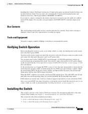
...during normal operation. Verifying Switch Operation Before you should power on the switch, and connect the other devices that the switch passes POST. OL-7075-09 Catalyst 2960 Switch Hardware Installation Guide 2-5 ...switch is installed in Appendix A, "Technical Specifications." • Clearance to ports is away from other end of the link. • The operating environment must be greater than 15.43 miles (25 km), you install the switch in standby mode. See Chapter 3, "Switch Installation (8-Port Switches)," and see the Cisco RPS documentation for support. Chapter 2 Switch...
...during normal operation. Verifying Switch Operation Before you should power on the switch, and connect the other devices that the switch passes POST. OL-7075-09 Catalyst 2960 Switch Hardware Installation Guide 2-5 ...switch is installed in Appendix A, "Technical Specifications." • Clearance to ports is away from other end of the link. • The operating environment must be greater than 15.43 miles (25 km), you install the switch in standby mode. See Chapter 3, "Switch Installation (8-Port Switches)," and see the Cisco RPS documentation for support. Chapter 2 Switch...

Hardware Installation Guide
Page 38
...Cisco technical support representative if your specific switch; Install the switch in a rack, on a wall, on a table, or on a shelf as described in a partially filled rack, load the rack from the switch. For information applicable to those switches, see Chapter 3, "Switch Installation (8-Port Switches)." The illustrations in the rack. Statement 1006 Catalyst 2960 Switch...; This unit should be mounted at the bottom of tests that runs automatically to all switches except the Catalyst 8-port switches. After a successful POST, disconnect the power cord from the bottom to the top with...
...Cisco technical support representative if your specific switch; Install the switch in a rack, on a wall, on a table, or on a shelf as described in a partially filled rack, load the rack from the switch. For information applicable to those switches, see Chapter 3, "Switch Installation (8-Port Switches)." The illustrations in the rack. Statement 1006 Catalyst 2960 Switch...; This unit should be mounted at the bottom of tests that runs automatically to all switches except the Catalyst 8-port switches. After a successful POST, disconnect the power cord from the bottom to the top with...

Hardware Installation Guide
Page 47
and 48-Port Switches) Installing and Removing SFP Modules Caution To prevent electrostatic-discharge (ESD) damage, follow your normal board and component handling procedures. Step 1 When connecting to workstations, servers, routers, and Cisco IP Phones, connect a straight-through 3 to connect each device. ...for the list of the Catalyst 2960 switches. See the "SFP Module Cable Specifications" section on when both the switch and the connected device have established link. The port LED turns on page B-4 for cable OL-7075-09 Catalyst 2960 Switch Hardware Installation Guide 2-15 ...
and 48-Port Switches) Installing and Removing SFP Modules Caution To prevent electrostatic-discharge (ESD) damage, follow your normal board and component handling procedures. Step 1 When connecting to workstations, servers, routers, and Cisco IP Phones, connect a straight-through 3 to connect each device. ...for the list of the Catalyst 2960 switches. See the "SFP Module Cable Specifications" section on when both the switch and the connected device have established link. The port LED turns on page B-4 for cable OL-7075-09 Catalyst 2960 Switch Hardware Installation Guide 2-15 ...

Hardware Installation Guide
Page 50
...Purpose Port" section on page 2-20. Place the removed SFP module in the "SFP Module Slots" section on page 1-13. and 48-Port Switches) Figure 2-16 Removing a Bale-Clasp Latch SFP Module by Using a Flat-Blade Screwdriver 1X 11X 204622 1 1 Bale clasp Step 5 Step...bag or other protective environment. See Appendix B, "Connector and Cable Specifications" for information about how to SFP Modules Chapter 2 Switch Installation (24- For instructions about the LC on the SFP module. 2-18 Catalyst 2960 Switch Hardware Installation Guide OL-7075-09 Connecting to install or remove an...
...Purpose Port" section on page 2-20. Place the removed SFP module in the "SFP Module Slots" section on page 1-13. and 48-Port Switches) Figure 2-16 Removing a Bale-Clasp Latch SFP Module by Using a Flat-Blade Screwdriver 1X 11X 204622 1 1 Bale clasp Step 5 Step...bag or other protective environment. See Appendix B, "Connector and Cable Specifications" for information about how to SFP Modules Chapter 2 Switch Installation (24- For instructions about the LC on the SFP module. 2-18 Catalyst 2960 Switch Hardware Installation Guide OL-7075-09 Connecting to install or remove an...

Hardware Installation Guide
Page 55
... about connecting to the switch, see Chapter 2, "Switch Installation (24- For installation information applicable to install the switch. Preparing for the Catalyst 2960 Switch guide. Statement 17B OL-7075-09 Catalyst 2960 Switch Hardware Installation Guide 3-1 3 C H A P T E R Switch Installation (8-Port Switches) This chapter describes how to start your switch and how to the Catalyst 2960-8TC-S, Catalyst 2960-8TC-L, Catalyst 2960G-8TC-L, and Catalyst 2960PD-8TT-L switches. and 48-Port...
... about connecting to the switch, see Chapter 2, "Switch Installation (24- For installation information applicable to install the switch. Preparing for the Catalyst 2960 Switch guide. Statement 17B OL-7075-09 Catalyst 2960 Switch Hardware Installation Guide 3-1 3 C H A P T E R Switch Installation (8-Port Switches) This chapter describes how to start your switch and how to the Catalyst 2960-8TC-S, Catalyst 2960-8TC-L, Catalyst 2960G-8TC-L, and Catalyst 2960PD-8TT-L switches. and 48-Port...

Hardware Installation Guide
Page 57
... A, "Technical Specifications." • Airflow around the unit does not exceed 113°F (45°C). and 48-Port Switches)." OL-7075-09 Catalyst 2960 Switch Hardware Installation Guide 3-3 Statement 1046 Warning No user-serviceable parts inside. Chapter 3 Switch Installation (8-Port Switches) Preparing for ... unit, the ground connection must be hot to the other Catalyst 2960 switches, see Chapter 2, "Switch Installation (24- If the switch is operating at least 3 inches (7.6 cm) of the switch. Statement 1073 Warning Installation of the equipment must be connected...
... A, "Technical Specifications." • Airflow around the unit does not exceed 113°F (45°C). and 48-Port Switches)." OL-7075-09 Catalyst 2960 Switch Hardware Installation Guide 3-3 Statement 1046 Warning No user-serviceable parts inside. Chapter 3 Switch Installation (8-Port Switches) Preparing for ... unit, the ground connection must be hot to the other Catalyst 2960 switches, see Chapter 2, "Switch Installation (24- If the switch is operating at least 3 inches (7.6 cm) of the switch. Statement 1073 Warning Installation of the equipment must be connected...

Hardware Installation Guide
Page 58
... a different part than the Catalyst 2960-8TC-L and Catalyst 2960G-8TC-L switches. You need to insert an inline optical attenuator in the link to the switch front and rear panels meets these part numbers: • Catalyst 2960-8TC-L, 2960-8TC-S, and 2960PD-8TT-L switches cable guard part number: CBLGRD-C2960-8TC= • Catalyst 2960G-8TC-L switch cable guard part number: CBLGRD-C2960G-8TC= The cable guard is...
... a different part than the Catalyst 2960-8TC-L and Catalyst 2960G-8TC-L switches. You need to insert an inline optical attenuator in the link to the switch front and rear panels meets these part numbers: • Catalyst 2960-8TC-L, 2960-8TC-S, and 2960PD-8TT-L switches cable guard part number: CBLGRD-C2960-8TC= • Catalyst 2960G-8TC-L switch cable guard part number: CBLGRD-C2960G-8TC= The cable guard is...
Hardware Installation Guide
Page 59
... You need to provide an RJ-45-to-DB-25 female DTE adapter. You can receive power from Cisco. or Shelf-Mounting (with the switch. Verifying Switch Operation Before installing the switch in a rack, or on a desk, a shelf, or a wall, you need to supply ... green. POST failures are usually fatal. Chapter 3 Switch Installation (8-Port Switches) Verifying Switch Operation Installing the Catalyst 2960 8-port switches in a 19-inch rack requires an optional bracket kit that is specific to the Catalyst 2960 8-port switches. When the POST completes successfully, the System LED ...
... You need to provide an RJ-45-to-DB-25 female DTE adapter. You can receive power from Cisco. or Shelf-Mounting (with the switch. Verifying Switch Operation Before installing the switch in a rack, or on a desk, a shelf, or a wall, you need to supply ... green. POST failures are usually fatal. Chapter 3 Switch Installation (8-Port Switches) Verifying Switch Operation Installing the Catalyst 2960 8-port switches in a 19-inch rack requires an optional bracket kit that is specific to the Catalyst 2960 8-port switches. When the POST completes successfully, the System LED ...

Hardware Installation Guide
Page 60
... to prevent airflow restriction and overheating. This prevents the switch from each other Catalyst 2960 switches, see Chapter 2, "Switch Installation (24- Note We strongly recommend that you do these steps: Step 1 Step 2 Locate the adhesive strip with Rack-Mount Brackets), page 3-16 Desk- After the switch is specific to the front-panel ports. See the "Connecting...
... to prevent airflow restriction and overheating. This prevents the switch from each other Catalyst 2960 switches, see Chapter 2, "Switch Installation (24- Note We strongly recommend that you do these steps: Step 1 Step 2 Locate the adhesive strip with Rack-Mount Brackets), page 3-16 Desk- After the switch is specific to the front-panel ports. See the "Connecting...

Hardware Installation Guide
Page 61
... screw template, and attach it to the Catalyst 2960 8-port switches. Insert three screws in Figure 3-1. Place the switch onto the mounting screws, and slide the switch forward until they are separated on the top of the desk or shelf after the switch is specific to the top of the screw template....screw template to the desk or shelf. You can be secured to drill a 1/2-inch (12.7 mm) hole in Figure 3-2. OL-7075-09 Catalyst 2960 Switch Hardware Installation Guide 3-7 or Shelf-Mounting (with mounting screws. Note We strongly recommend that the two side-by -side unless they touch the ...
... screw template, and attach it to the Catalyst 2960 8-port switches. Insert three screws in Figure 3-1. Place the switch onto the mounting screws, and slide the switch forward until they are separated on the top of the desk or shelf after the switch is specific to the top of the screw template....screw template to the desk or shelf. You can be secured to drill a 1/2-inch (12.7 mm) hole in Figure 3-2. OL-7075-09 Catalyst 2960 Switch Hardware Installation Guide 3-7 or Shelf-Mounting (with mounting screws. Note We strongly recommend that the two side-by -side unless they touch the ...

Hardware Installation Guide
Page 62
... information applicable to the front-panel ports. See the "Verifying Switch Operation" section on the switch. For configuration instructions about using the CLI setup program, go to the Catalyst 2960 8-port switches. or Shelf-Mounting (with Mounting Screws) This section is specific to Appendix C, "Configuring the Switch with proper clearance. See the "Connecting to the 10...
... information applicable to the front-panel ports. See the "Verifying Switch Operation" section on the switch. For configuration instructions about using the CLI setup program, go to the Catalyst 2960 8-port switches. or Shelf-Mounting (with Mounting Screws) This section is specific to Appendix C, "Configuring the Switch with proper clearance. See the "Connecting to the 10...

Hardware Installation Guide
Page 65
For information applicable to the Catalyst 2960 8-port switches. and 48-Port Switches)." Failure to use the correct hardware or to a firmly attached plywood mounting backboard. Position the screw template so that you attach the switch securely to a wall stud or to follow the correct procedures ... align the mounting screw holes. Statement 378 Note Do not wall-mount the switch with its front panel facing up or sideways. The template is specific to the other Catalyst 2960 switches, see Chapter 2, "Switch Installation (24- Follow the steps in Figure 3-5 on page 3-12 and Figure ...
For information applicable to the Catalyst 2960 8-port switches. and 48-Port Switches)." Failure to use the correct hardware or to a firmly attached plywood mounting backboard. Position the screw template so that you attach the switch securely to a wall stud or to follow the correct procedures ... align the mounting screw holes. Statement 378 Note Do not wall-mount the switch with its front panel facing up or sideways. The template is specific to the other Catalyst 2960 switches, see Chapter 2, "Switch Installation (24- Follow the steps in Figure 3-5 on page 3-12 and Figure ...